Scope
Install ducts in dropped ceilings or “fur-down” duct chases to keep the ducts within the home's thermal envelope.
- Install drywall at the ceiling plane before the chase is framed to form a continuous air barrier between the top of the chase and the unconditioned attic or floor cavity above.
- Install chase framing.
- Install the sealed, insulated ducts.
- Install drywall on chase sides and bottom when installing drywall in remainder of the house.
Several trades are critical to the success of this technique:
- HVAC Designers - Design a compact duct layout that does not cross load bearing walls. Use ACCA Manual D to determine the duct size needed.
- Framers - Construct any non-load bearing walls that will serve as one side of the chase with a gap of ¾” between the top plate of the wall and the bottom chord of the attic trusses so that drywall can be installed over the top plates to form a continuous ceiling for the duct chase. Construct remaining duct chase after chase ceiling drywall is installed.
- Drywallers - Install drywall above duct chase location before framing the chase and before installing the ducting. The remaining drywall in the room will be installed after the duct and chase framing are installed.
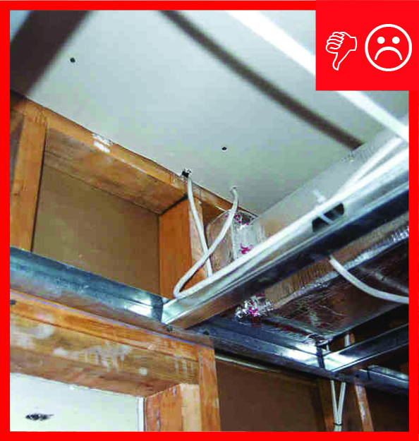
- Plumbers and Electricians - Do not use the duct chase as a chase for electrical wiring or plumbing, and do not cut holes through the chase walls.
- All Trades - Participate in a pre-construction meeting to understand construction sequencing steps for this technique, which is further described in the Description tab of this guide.
See the Compliance Tab for related codes and standards requirements, and criteria to meet national programs such as DOE’s Zero Energy Ready Home program, ENERGY STAR Single-Family New Homes, and Indoor airPLUS.
Description
Implementing an interior duct system involves bringing the forced air system, including the air handler, within the dwelling’s air and thermal barrier and integrating the new detail into the design and construction process. There are many benefits to bringing the ducts and HVAC equipment within conditioned space – the HVAC equipment is protected from the extreme temperatures of unconditioned attics and crawlspaces, the furnace and air handler are easier to access for maintenance, interior installation requires far fewer holes through the building envelope, and any air losses through duct or cabinet leaks will go to conditioned space rather than being lost to unconditioned space. Installing the ducts in a dropped ceiling chase in a central hallway (with the air handler in a utility closet) is one option for locating ducts in conditioned space. For other options, see the guides Unvented Attic Insulation, Unvented Crawlspaces and Conditioned Basements, Raised Ceilings, Ducts Buried in Attic Insulation, Ducts Buried in Attic Insulation and Encapsulated, and Ducts in Interstitial Floor Framing. Another option is to install a heating and cooling system that does not require ducts, such as ductless heat pumps and radiant floor heating.
In a dropped ceiling or “fur-down” duct chase installation, a critical detail is the integrity of the air barrier between the top of the chase and the unconditioned attic or floor cavity above.
The builder must make a clear and consistent commitment to building an interior duct system. Then this commitment must be communicated to all of the relevant trades. All involved parties (trades, designers, architects, etc.) must be dedicated to this task. Four critical trades are the home designer, the HVAC designers and installers, the drywall installers, and the framing carpenters. The best opportunity to minimize costs while ensuring an aesthetically pleasing outcome is during the preliminary schematic design phase of home construction.
- HVAC designers must first determine the needed size of the duct work based on the ACCA Manual D calculation.
- The size and location of the chase can now be planned by the house designer.
- The method and technique of constructing the chase must be clearly planned, documented, and communicated to the drywall contractors, field crews, and carpenters.
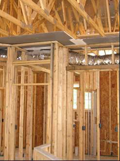
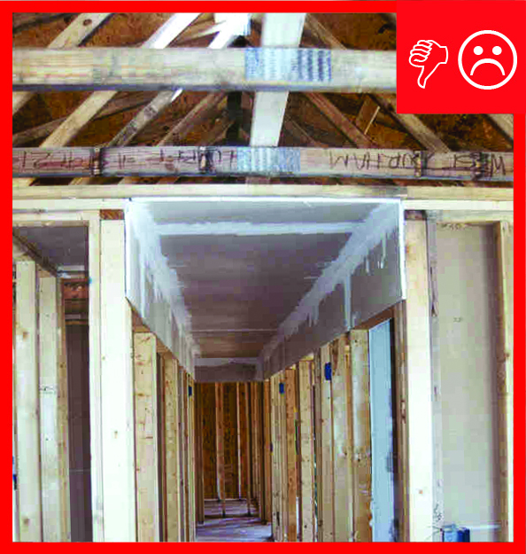
U.S. Department of Energy Building America Partners Tommy Williams Homes and Florida H.E.R.O. have developed and implemented an innovative approach to the dropped ceiling or fur-down chase method that addresses the typical failure point of fur-down chases: the integrity of the air sealing between the chase and the attic above. In the common approach to a fur down chase (Figure 1), the air barrier is adhered to the underside of the truss bottom chords and to the face of the studs in the adjacent hallway walls (between the top plates). The intersection of the air barrier material with these framing members creates a complex set of air sealing details, as shown in the circle in Figure 1. The innovative approach described in this guide eliminates the majority of these leakage paths.

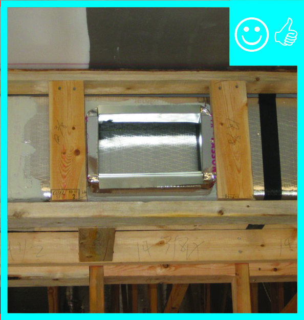
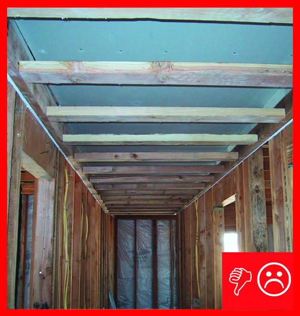
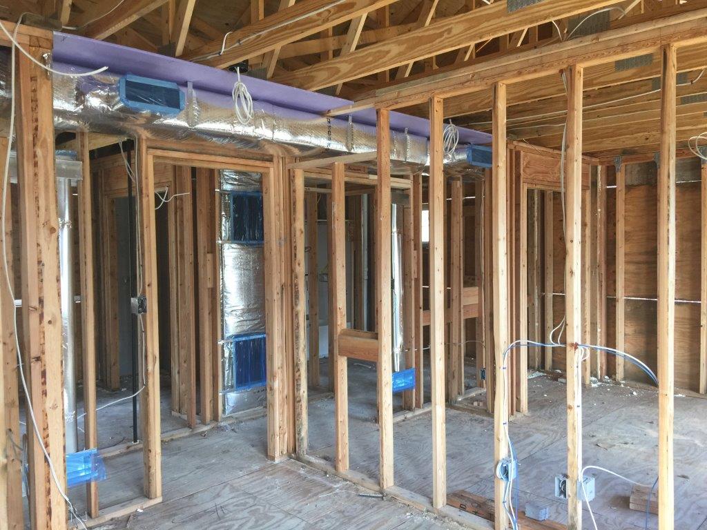
By designing the chase’s path to avoid intersecting load-bearing walls, air sealing of the chase’s top plane, or ceiling, is fairly easy. For chases that will use a non-load-bearing interior wall for one or both sides of the chase, the walls can be constructed to leave a gap of ¾” between the top plate of the wall and the bottom chord of the attic trusses. The ¾” space allows for the installation of drywall over the top plates of the walls to form a continuous ceiling or top of the duct chase. If the chase walls will not be part of an interior wall, the drywall for the ceiling of the chase is installed first. The chase’s ceiling drywall should be extended beyond the borders of the chase over the top plates of the walls and anticipated framing of the chase sides (Figure 2).

This drywall will be the primary air barrier separating the chase from unconditioned attic space above. It is continuous over the wall framing, thereby eliminating the complex intersections and air sealing details between the ceiling of the chase and the tops of the walls.
The HVAC ducts are hung after the chase ceiling drywall is installed. Then, the framing for the sides and bottom of the chase are installed. These will be drywalled when the interior walls of the home are drywalled.
With information derived from the HVAC designer’s Manual J and D calculations, the designer can finalize plans that consider the size requirements and path of the distribution system. This may require an iterative approach as the vertical dimensions of the required duct sizes, the chase, and the ceiling are refined. Preplanning can help facilitate a compact duct design and reduce the amount of ducting needed.
Ducts brought into the conditioned space should include both the return and supply ducts to provide maximum efficiency for the effort. To reduce the size and amount of chase required and to avoid duct sizing miss-matches between the supplies and returns, one or more central main return registers can be installed in central locations in the home with passive return air pathways consisting of transoms over the interior doors of occupiable rooms (bedrooms). The transoms must be sized to allow adequate return air passage to the main body of the house with the goal of maintaining nearly neutral pressure with respect to the home (<2.5 Pascals) when the mechanical system is operating and the bedroom doors are closed. (See the guides Transfer Grilles and Jump Ducts for more information.) The passive transom returns should be sized at least 1 ½ times larger than the room’s cumulative supply duct areas. The supply ducts should be sized according to ACCA Manual D. By eliminating all ducted returns, labor and material costs are reduced. In addition, the system’s overall operating static pressure can be reduced, allowing for less wear on the air handler’s fan motor. Partner builders implementing transom returns in hundreds of Building America homes have not received any noise or light-related complaints. Pressure mapping during the final commissioning should be performed to confirm that the return air system is working as designed.
How to Build a Dropped Ceiling or Fur-Down Chase
Step 1: Plan ahead and document the location, style, and path of the interior duct chase; show the path on the floor plan with dimensions (Figure 3). Provide a detail of any additional framing necessary to complete the chase after the mechanical rough in.

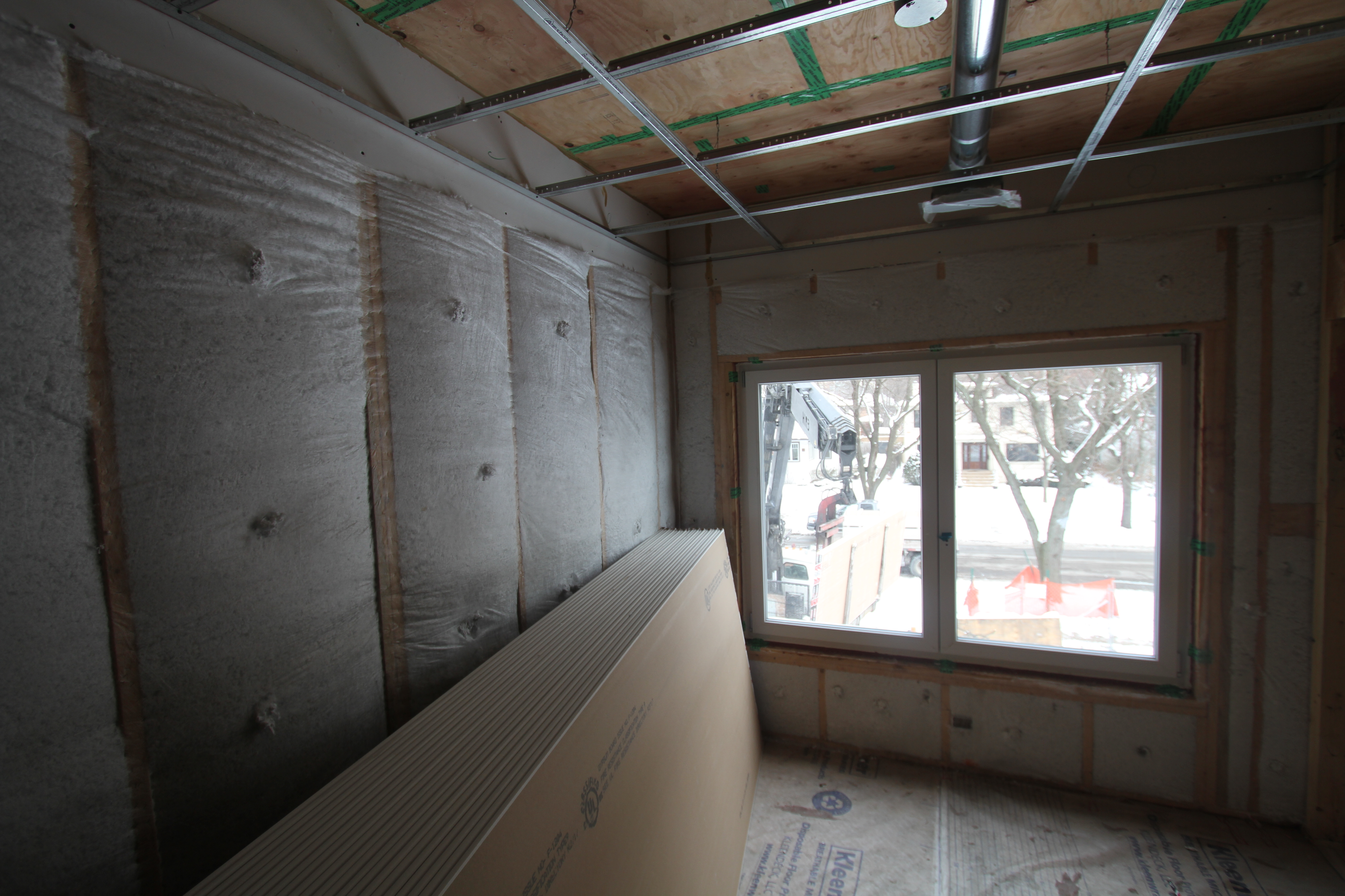
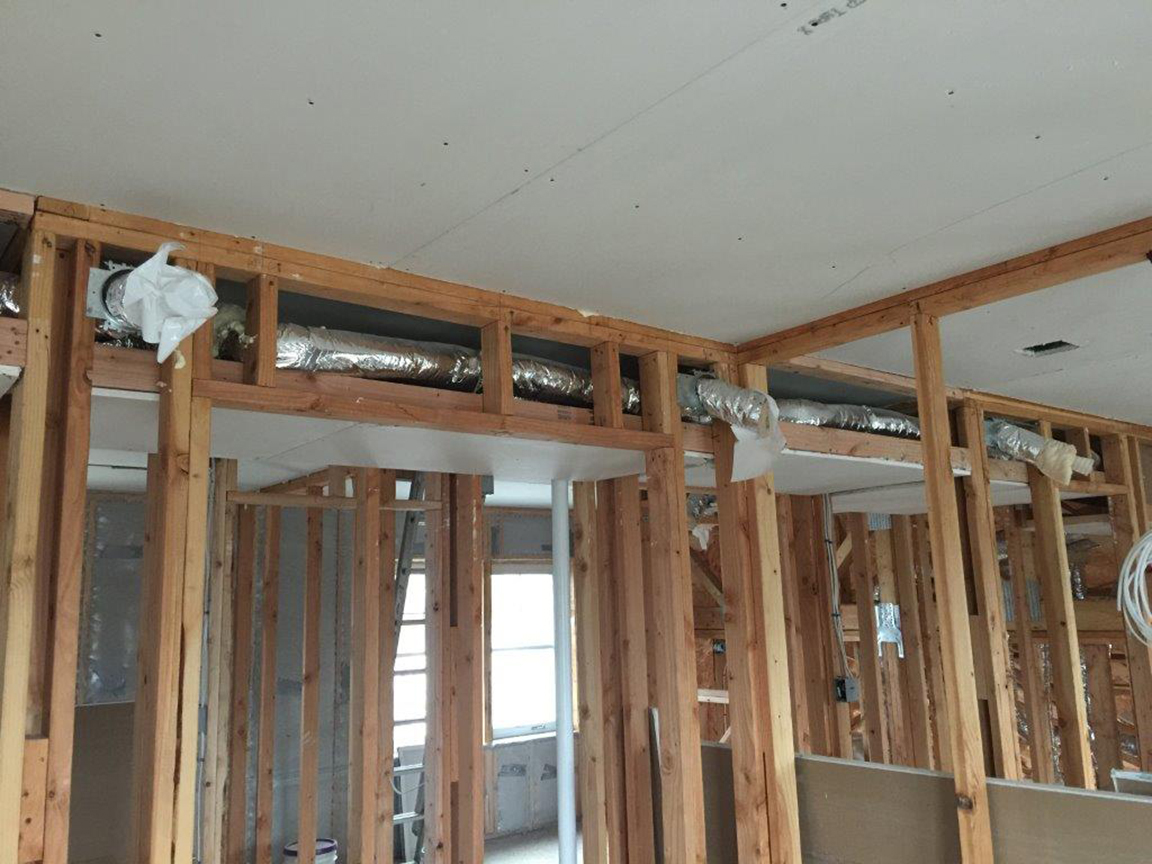
Step 2: Install sheetrock at the top of the chase path as indicated in the design plan (Figure 3).
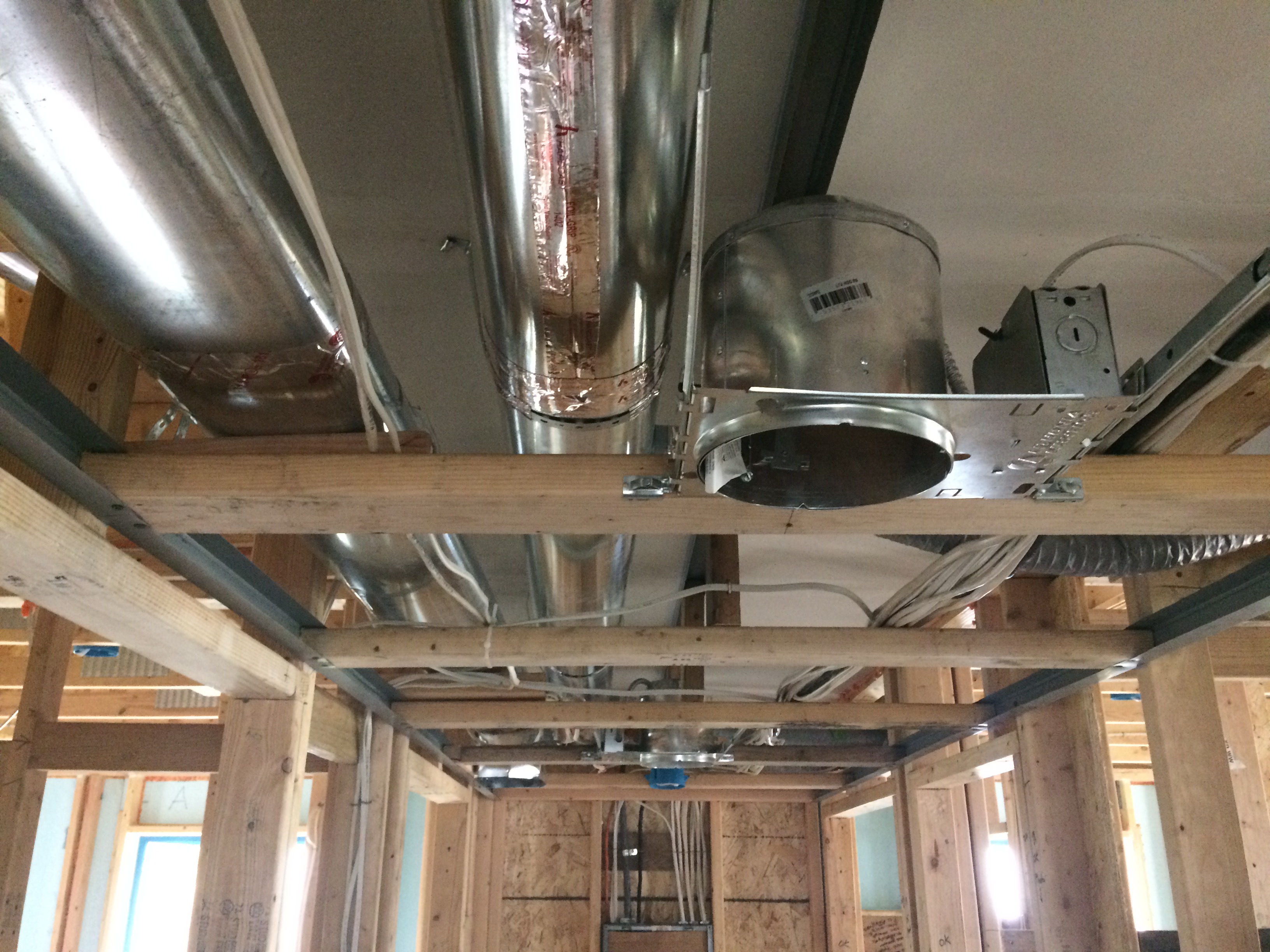
Step 3: Fabricate and install the supply ductwork in the chase (Figure 4). Fabricate the duct system. Construct and air seal as much of the duct system as possible on the ground where it is easier to align the sections and reach the joints to seal them with mastic. The main supply trunk lines and supply ducts are then hung from the drywall using strapping secured to the framing. Care must be taken to avoid damaging the chase’s ceiling. Rigid ducts are used whenever possible because they are easier to manage than flex ducts during the lift from floor to ceiling.

Step 4: Install the framing for the sides and bottom of the chase (Figure 5). Care must be used to not penetrate the chase’s ceiling while completing the framing of the chase.

Step 5: Install drywall on the sides and bottom of the chase when the rest of the house is drywalled, finishing the chase’s construction (Figure 6).

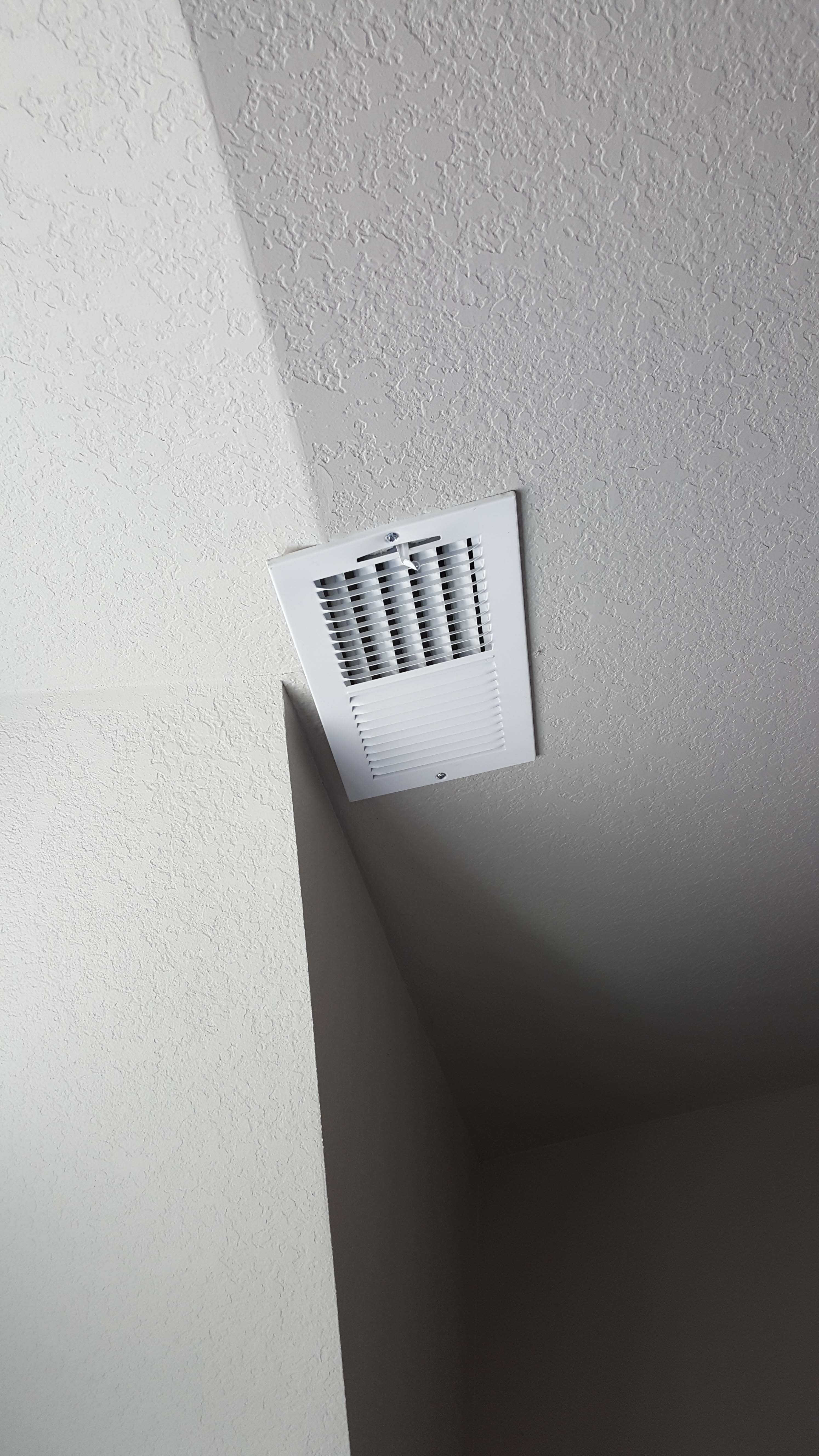
Step 6: Install return transoms (Figure 7) or other passive return paths to a central return register (jump ducts, etc.).

Success
Interior duct implementation requires trade coordination, which is best accomplished by a site meeting after house dry-in (when the building shell has been sufficiently completed to keep out wind, rain, and snow). This meeting should include the designer; sales/marketing professionals; and mechanical, insulation, plumbing, electrical, framing, sheet rockers, and solar contractors. The objective is to minimize the need to alter or redo work because of a lack of knowledge of the design and construction requirements. A meeting provides the opportunity to clearly communicate that the home will be built differently compared to the normal practice of having ducts in the attic/crawlspace. Questions raised in the discussion can be quickly answered by the appropriate trade representative.
Because a dropped ceiling chase is built early in the construction process, it is in danger of subsequent damage by trades people performing later tasks. Diligent inspection and constant oversight by an informed site supervisor are necessary to ensure that all trades people involved with the process (not just the crew bosses) are aware of the interior duct system and its function. The bid documents and scopes of work for plumbing and electrical contractors should include an advisement that the duct chase (drawn on the plans) cannot be used for electrical or plumbing runs. Even after the house is completed, interior duct work is subject to damage when the new homeowners have alarm, cable, and telephone services installed. Therefore, homeowner awareness of the duct system’s function is another important part of successfully implementing an interior duct system.
Advisory notices to cable, security, and telephone installers should be posted in conspicuous locations such as the panel box, attic access hatch, wiring service entrance, etc. Since these notices cannot clearly identify the location of the air boundary, they should advise the installer to seal any penetrations to drywall made from unconditioned spaces. Though it should be standard practice and is often required by code, virtually all services that are installed post-occupancy are never inspected.
Verification of an interior duct system can be executed during house pressure testing. Standardized testing protocols require depressurization of the house and duct system. During this operation, air pressure in the chase can be checked to verify its location, either interior or exterior, or somewhere in between. Testing apparatus include a blower door to depressurize the house and a duct blaster to depressurize the duct system. Typical blower door testing involves depressurizing the house to a standard pressure with respect to the outside, usually 50 Pascals, using a calibrated fan. When the house is subjected to this depressurization, the pressure in the duct chase can be checked with respect to the house. If there is no pressure difference between the house and chase, the chase is truly interior. In other words, it is completely inside the pressure boundary of the house. Depending on the pressure variation, a determination can be made regarding the integrity of the duct chase.
Two tests can be performed with the duct blaster: duct leakage to the outdoors, which measures only that duct leakage outside of the home’s air barrier, for example into an unconditioned attic, and total duct leakage, which measures duct leakage across the entire duct system, both into the home’s interior conditioned space and to the outside. Duct leakage to the outside results in energy lost. If the chase is completely sealed from unconditioned spaces, there should be no duct leakage to the outside. Obviously, if leakage is detected with this test, it indicates that the duct chase or the duct system itself is connected to the outside in some fashion, revealing a breakdown in the air barrier of the chase. See the guides Duct Leakage to Outdoors and Total Duct Leakage Tests for more information.
Climate
No climate specific information applies.
Training

Compliance
Compliance
The Compliance tab contains both program and code information. Code language is excerpted and summarized below. For exact code language, refer to the applicable code, which may require purchase from the publisher. While we continually update our database, links may have changed since posting. Please contact our webmaster if you find broken links.
ENERGY STAR Single-Family New Homes, Version 3/3.1 (Rev. 11)
National Rater Field Checklist
Thermal Enclosure System.
2. Fully-Aligned Air Barriers.7 At each insulated location below, a complete air barrier is provided that is fully aligned as follows:
Ceilings: At interior or exterior horizontal surface of ceiling insulation in Climate Zones 1-3; at interior horizontal surface of ceiling insulation in Climate Zones 4-8. Also, at exterior vertical surface of ceiling insulation in all climate zones (e.g., using a wind baffle that extends to the full height of the insulation in every bay or a tabbed baffle in each bay with a soffit vent that prevents wind washing in adjacent bays).8
2.1 Dropped ceilings / soffits below unconditioned attics, and all other ceilings.
Footnote 7) For purposes of this Checklist, an air barrier is defined as any durable solid material that blocks air flow between conditioned space and unconditioned space, including necessary sealing to block excessive air flow at edges and seams and adequate support to resist positive and negative pressures without displacement or damage. EPA recommends, but does not require, rigid air barriers. Open-cell or closed-cell foam shall have a finished thickness ≥ 5.5 in. or 1.5 in., respectively, to qualify as an air barrier unless the manufacturer indicates otherwise. If flexible air barriers such as house wrap are used, they shall be fully sealed at all seams and edges and supported using fasteners with caps or heads ≥ 1 in. diameter unless otherwise indicated by the manufacturer. Flexible air barriers shall not be made of kraft paper, paper-based products, or other materials that are easily torn. If polyethylene is used, its thickness shall be ≥ 6 mil.
Footnote 8) All insulated ceiling surfaces, regardless of slope (e.g., cathedral ceilings, tray ceilings, conditioned attic roof decks, flat ceilings, sloped ceilings), must meet the requirements for ceilings.
Please see the ENERGY STAR Single-Family New Homes Implementation Timeline for the program version and revision currently applicable in your state.
DOE Zero Energy Ready Home (Revision 07)
Exhibit 1 Mandatory Requirements.
Exhibit 1, Item 1) Certified under the ENERGY STAR Qualified Homes Program or the ENERGY STAR Multifamily New Construction Program.
Exhibit 1, Item 3) Duct distribution systems located within the home’s thermal and air barrier boundary or an optimized location to achieve comparable performance.
Footnote 14) Exceptions and alternative compliance paths to locating 100% of forced-air ducts in home’s thermal and air barrier boundary are:
- Up to 10’ of total duct length is permitted to be outside of the home’s thermal and air barrier boundary.
- Ducts are located in an unvented attic, regardless of whether this space is conditioned with a supply register.
- Ducts are located in a vented attic with all of the following characteristics: [Note that in either of these designs the HVAC equipment must still be located within the home’s thermal and air barrier boundary.]
- In Moist climates (Zones 1A, 2A, 3A, 4A, 5A, 6A and 7A per 2015 IECC Figure R301.1) and Marine climates (all “C” Zones per 2015 IECC Figure R301.1), minimum R-8 duct insulation with an additional minimum 1.5” of closed-cell spray foam insulation encapsulating the ducts; duct leakage to outdoors ≤ 3 CFM25 per 100 ft2 of conditioned floor area (in addition to meeting total duct leakage requirements from Section 4.1 of the ENERGY STAR HVAC Rater checklist); and ductwork buried under at least 2” of blown-in insulation.
- In Dry climates (all “B” Zones per 2015 IECC Figure R301.1), minimum R-8 duct insulation; duct leakage to outdoors ≤ 3 CFM25 per 100 ft2 of conditioned floor area (in addition to meeting total duct leakage requirements from Section 4.1 of the ENERGY STAR HVAC Rater checklist); and ductwork buried under at least 3.5” of blown-in insulation.
- Systems which meet the criteria for “Ducts Located in Conditioned Space” as defined by the 2018 IECC Section R403.3.7
- Jump ducts which do not directly deliver conditioned air from the HVAC unit may be located in attics if all joints, including boot-to-drywall, are fully air sealed with mastic or foam, and the jump duct is fully buried under the attic insulation.
- Ducts are located within an unvented crawl space.
- Ducts are located in a basement which is within the home’s thermal boundary.
- Ductless HVAC system is used.
2012, 2015, 2018, and 2021 International Energy Conservation Code (IECC)
Section R403.2.3 (R403.3.5 in 2015, 2018 IECC and R403.3.7 in 2021 IECC) Building cavities (Mandatory). No building framing cavities should be used as ducts or plenums.
Retrofit: 2009, 2012, 2015, 2018, and 2021 IECC
Section R101.4.3 (in 2009 and 2012). Additions, alterations, renovations, or repairs shall conform to the provisions of this code, without requiring the unaltered portions of the existing building to comply with this code. (See code for additional requirements and exceptions.)
Chapter 5 (in 2015, 2018, 2021). The provisions of this chapter shall control the alteration, repair, addition, and change of occupancy of existing buildings and structures.
2012, 2015, 2018, and 2021 International Residential Code (IRC)
Chapter 16 – Duct Systems, M1601.3 Duct Insulation Materials. Duct insulation materials are required to have a flame spread index of 25 or less and a smoke developed index of 50 or less. There is an exemption for foam, flame spread index of 25 or less and a smoke developed index of 450 or less, and the foam is protected with an ignition barrier.
Retrofit: 2009, 2012, 2015, 2018, and 2021 IRC
Section R102.7.1 Additions, alterations, or repairs. Additions, alterations, renovations, or repairs shall conform to the provisions of this code, without requiring the unaltered portions of the existing building to comply with the requirements of this code, unless otherwise stated. (See code for additional requirements and exceptions.)
Appendix J regulates the repair, renovation, alteration, and reconstruction of existing buildings and is intended to encourage their continued safe use.
2010 Florida Residential Building Code
M1601.4.1.8 Cavities of the building structure. No building framing cavities should be used to deliver air from or return to the conditioning system unless they contain an approved, insulated air duct insert. An exception is made for return plenums.
Retrofit
SCOPE
Bring air distribution system including air handling equipment and duct work into the conditioned space of the house.
- Following the design considerations outlined in the Main Body’s Description Tab, layout a duct system that can be enclosed by constructing or retrofitting soffits to form ducts chases. If needed, relocate air handling equipment into home’s interior or create a sealed closet around any air handling equipment installed in the garage, crawlspace or attic and connect it to the home’s conditioned space.
- Lay out the duct system incorporating the chase work in dropped ceilings, soffits, and architectural features where possible.
- Pre-cut and seal any wall or ceiling penetrations necessary for constructing the chase; seal around any penetrations in the path of the chase. Repair any pre-existing damage in chase path.
- Install sealed and insulated ducts by suspending from the ceiling.
- Enclose the duct work with soffit framing.
- Install drywall, mud, and tape or otherwise finish the soffit exterior.
- For more on duct sealing and insulating, see the U.S. Department of Energy’s Standard Work Specifications. The Specifications also discuss safe work practices.
DESCRIPTION
Attempting to retrofit ducts in a dropped ceiling is a challenging installation involving replacing or moving existing ducts and HVAC equipment out of an unconditioned attic or crawlspace and into the interior of the house. In all but the simplest floorplans this will be a difficult and most often not cost-effective retrofit. Installing a dropped ceiling or fur-down duct system in a retrofit situation is more challenging and less likely to be successful than implementing the system in new construction. The home’s layout is presumably fixed, and the chase system must be made to work with the existing home floor plan. Because of the difficulty involved in moving an existing duct system out of the attic or crawlspace, this retrofit would likely involve abandoning that equipment in place, sealing off and insulating duct openings through ceilings or floors, and installing a new system within the home. When evaluating energy savings and payback periods, consider the alternatives described below. One advantage if moving the ducts into a dropped ceiling chase is that the air barrier above the chase should already be complete and airtight, or could be made that way with minimal effort.
In lieu of retrofitting an interior duct system via a dropped ceiling, consider these alternatives:
- Alternative 1: Air seal and insulate the existing duct system, or replace the existing ducts with a new, compact, air-tight, well-insulated duct system that is in the same location as the existing duct system. This does not bring the ducts into conditioned space, but it produces some of the same results. OR
- Alternative 2: Retain the existing duct system and air handler in place and turn the existing attic into a sealed, insulated attic space by closing off vents and insulating along the underside of the roof line. (Also see the BASC guide “Below Deck Spray Foam Insulation for Existing Roofs.”) OR
- Alternative 3: Encapsulate the new or existing duct work in spray foam and “bury” it in additional blown insulation.
- Alternative 4: Replace the ducted equipment with non-ducted equipment installed in the home.
How to construct a dropped ceiling chase to install ducts in the conditioned space of an existing home.
The construction process is basically the same as the new construction process described in the Description tab, with the inclusion of a step prior to Step 1 and a replacement for Step 2.
Ensure that the planned implementation complies with the applicable codes and is performed by properly credentialed contractors.
Prior to Step 1: If the air handler is installed outside of the conditioned space, relocated the air handler into conditioned space. OR Construct an air-sealed closet around an air handler installed in a garage or attic.
Constructing an Air-Sealed Closet in the Garage or Attic. To construct a sealed closet around the air handling equipment already located in the garage or attic, see the guide “No Ducts or Air Handlers Located in Garage” by IBACOS. Ideally, air handlers and ducts should not be located in the garage. Don’t move the air handler into the garage as part of the retrofit. If an air handler is located in the garage prior to the retrofit, move it into the conditioned space of the home as part of the retrofit if possible. Do not locate duct supply or return registers in the garage.
- If the air handler must remain in the garage, construct an airtight closet around it.
- Install a self-closing door and weather-strip the door frame.
- Connect the closet to the home’s conditioned space via a sealed transfer grill or jump duct to ensure any depressurization of the closet draws air from the house, not the adjacent unconditioned space. In BASC see “Jump Ducts.”
- Seal all return or supply plenums in the new equipment room or closet in accordance with local codes. See “Duct Sealing,” “Sealed and Insulated Fiber Board Ducts,” “Sealed and Insulated Flex Ducts,” and “Sealed and Insulated Metal Ducts.”
Electric air handlers installed in garages or attics should also be encased in an air-sealed closet with a weather-stripped access door.
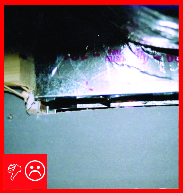
Replace Step 2: Ensure the chase path is well sealed to separate it from an unconditioned attic or wall cavities. Use code-approved sealants. Remove recessed lighting fixtures in the path of the chase and patch and seal the ceiling. Make and seal around any wall penetrations required by the chase path. Where the chase penetrates interior walls, install horizontal blocking to form a rough opening. Seal all gaps between the rough opening framing and the drywall. Figure 1 shows a duct going through the wall. No blocking or air sealing was installed around the duct so air can potentially move through the wall cavity to air leaks at either end that may communicate with an unconditioned attic or crawlspace. This air could potentially carry moisture which could condense on cold surfaces causing mold and moisture damage inside the walls.

SUCCESS
Care must be exercised when implementing these strategies. Moving the duct system into the home’s conditioned space can change the pressure-induced infiltration and exfiltration of the house. If there is atmospherically vented combustion equipment in the house, a combustion air zone pressure test should be performed. See Pre-retrofit Assessment for Combustion Safety for more information.
COMPLIANCE
See Compliance tab.
More
More Info.
Access to some references may require purchase from the publisher. While we continually update our database, links may have changed since posting. Please contact our webmaster if you find broken links.
The following authors and organizations contributed to the content in this Guide.
Florida Solar Energy Center, lead for the Building America Partnership for Improved Residential Construction (BA-PIRC), a DOE Building America Research Team
Sales
HVAC Ducts in Dropped Ceilings =

Comfort systems work much better when they are located inside the conditioned space of the home rather than in an unconditioned attic or crawl space. Dropped ceilings are one option for integrating heating and cooling ducts inside conditioned space. This entails building an airtight chase that could be hidden in a soffit or false ceiling in a hallway or closet.