In the last couple of articles, we used terminology relating to pressure control solenoids such as PWM, Frequency, and Duty Cycle. In this article, I thought I would go into depth on what these terms really mean and how they relate to solenoid control. As transmissions have gone from only a few pressure control solenoids to many or even having all of them as pressure control solenoids, a good understanding of these terms is critical for diagnosing error codes and testing components when vehicles come into your shop.
 PWM stands for “Pulse Width Modulation.” A quick google search yields a definition on Wikipedia. They define PWM as “a method of reducing the average power delivered by an electrical signal, by effectively chopping it up into discrete parts. The average value of voltage (and current) fed to the load is controlled by turning the switch between supply and load “on and off” very quickly. The longer the switch is on compared to the off periods, the higher the total power supplied to the load.”1
Let us break this down into what this means, especially in terms of solenoid control. Pressure control solenoids are current-controlled devices, meaning that the output pressure is a function of the current draw of the solenoid. In a properly functioning solenoid, the same current will give us the same output pressure each time we apply it. The easiest way to change the current on a solenoid is to vary the voltage applied to it. For example, if we apply 6 volts to the solenoid and it draws 0.8 amps, reducing it to 3 volts would reduce the current to 0.4 amps. By varying the voltage we apply to the solenoid, we can vary and control the current between 0 and the maximum amount of current needed to fully operate the solenoid (usually 1.2 to 1.5 Amps). Therefore, we can vary the pressure from the solenoid between 0 and the maximum pressure that the solenoid can output.
 Pulse Width Modulation is a method that allows us to do this. We switch (or pulse) a solenoid on and off very quickly (multiple times per second) between zero volts and ignition voltage. The amount of time it is at ignition voltage vs. off is the duty cycle. If it is on for 50% of the time and off for 50% of the time, this is a PWM signal at 50% duty cycle. If the ignition voltage is 12V, we are effectively powering the solenoid at 50% of this, or 6 Volts. If we reduce the on-time to 25% and the off-time to 75%, we now have a PWM signal at 25% duty cycle, and the solenoid is now effectively being powered at 3 volts. As we vary this amount of on-time vs. off time, we are modulating the pulse width. Hence this is where the term Pulse Width Modulation comes from (figure 1).
 Frequency as it relates to PWM is the number of times per second that we repeat the on and off cycle (figure 2). If we pulse the solenoid on and off at a given duty cycle 30 times a second, we have a frequency of 30 Hz. If you look through any GM literature on early GM four-speed transmissions, they clearly state the EPC solenoid had a frequency of 292.5Hz. This means that the EPC is pulsed 292.5 times per second. This was later changed to 585 Hz. Early Ford EPC solenoids were around 600 Hz. Many early lockup solenoids were in the 30-35 Hz range. Later model vehicles with multiple pressure control solenoids tend to use higher frequencies on the pressure control solenoids. Pulsing them from 1000 to 2500 Hz is now very common.
You might ask, “Why bother with PWM at all and not just vary the DC voltage to a solenoid like a benchtop power supply where I turn the knob to vary the output voltage?” Wouldn’t this be a much simpler way to control the solenoid? When it comes to electronics (especially in the case of a TCU) a variable DC supply such as one controlled by a microprocessor ends up being a somewhat complicated and expensive method for solenoid control. By comparison, even the most inexpensive and basic microprocessors have PWM capability built-in, and the actual programming code to accomplish it is also very simple. Hence even from the early days of pressure control solenoids, using PWM as a method of voltage control became the preferred way to control solenoids because for TCU hardware and software designers, it was very easy and inexpensive to implement.
 A second question you might ask, “Why are there so many different frequencies to control solenoids with PWM then? Why does everyone seem to use a different frequency?” There are two reasons for this. The first relates to the internal circuitry of the TCU. The internal parts used to determine the number of different frequencies easily available from the microprocessor in the TCU. The processor might have a base PWM frequency of 4000 Hz. With simple math internal to the processor, you can easily divide this by 4 and get 1000 Hz, or 8 and get 500 Hz. Since each auto manufacturer is going to use different electronics and different microprocessors, the exact frequencies available will vary from manufacturer to manufacturer.
The second and probably more important reason for a particular frequency is that as a general rule, the electrical frequency should be at least 10 times the mechanical frequency of the solenoid. What this means is that a solenoid can only physically respond so fast to abrupt changes in current. Let’s say we started pulsing the solenoid at 1 Hz and then slowly increased the frequency until we reached 30 Hz and found that it’s as fast that it can physically respond to this electrical signal. Above 30 times a second, it cannot actually move fast enough to keep up with the pulsing. 30Hz is the mechanical frequency of the solenoid. When we are controlling with a PWM signal, we want a smooth control so that the solenoid more or less gets an average current rather than pulses. This allows the internal valve to “float,” and it moves smoothly as we increase or decrease the duty cycle so that the pressure holds steady and smoothly increases or decreases. For this solenoid, the PWM frequency should be at least 10x this mechanical frequency, or 300 Hz.
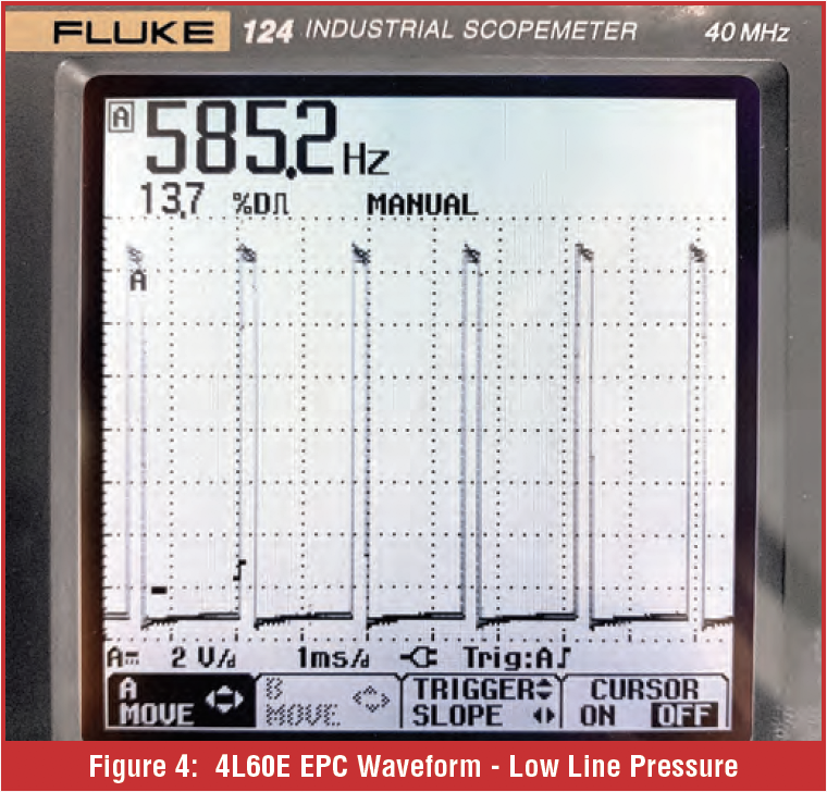
Now that we have covered the terminology and how PWM works, you can see this for yourself on vehicles in your shop. Many of the good automotive graphing scopes used for looking at sensors and waveforms do a very good job of displaying these PWM waveforms. Many will automatically give you both frequency and duty cycle measurements. Try back probing a vehicle harness on the two wires to a pressure control solenoid at the transmission connector. Start the vehicle and let it idle and observe what you see on the scope. You should see a PWM waveform, like in figures 3 and 4. Since this is a 4L60E, upon initial startup, the line pressure was higher as seen in Figure three. Once the vehicle warmed up a bit, the line pressure dropped, and the typical idle and as you shifted from P-R-N-D can be seen in figure four. As you can see, as the duty cycle changes, this means the solenoid current changes, and therefore the line pressure is being modulated inside the transmission. If this were a later model clutch to clutch unit, we would be modulating the apply pressure to the particular clutch the solenoid controls.
As you observe these waveforms on your scope, I hope that this helps bridge the gap between what PWM control is and what is physically happening inside the transmission. This understanding should also help you with your diagnosis process when vehicles come into your shop.
References:
1Wikipedia contributors, “Pulse-width modulation,” Wikipedia, The Free Encyclopedia