Introduction
We have created and described several voltage regulator circuits in our tutorials and articles. We have also tried to explain the importance that how it takes the varying voltage from input and generates the constant voltage at the output side. Moreover, we have learned that constant voltage protects the device from harm and saves it from any unusual conditions. But all of this is done by the voltage regulators. thus, 7805 is one of the most common voltage regulators. So, we have decided that in this tutorial we will discuss the “7805 IC Circuit Diagram”. But, before knowing the circuit diagram let’s first explore the IC 7805.
An overview of IC 7805
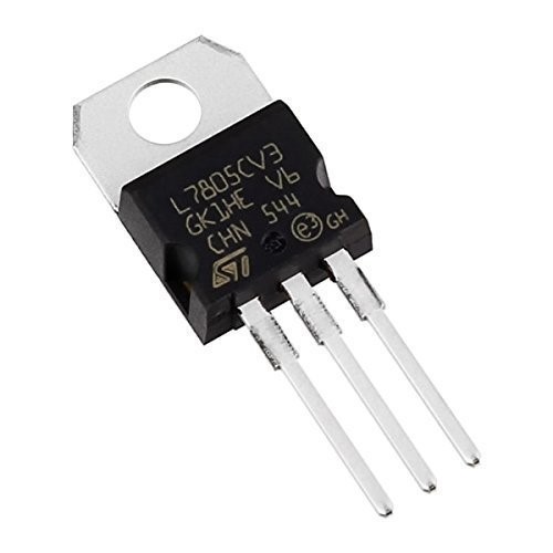
Firstly, the name 7805 hides very interesting information. 78 in 7805 describes it as a positive voltage regulator while 05 in the name implies that it gives 5V at the output. Hence, it means that this IC generates positive 5 volts at a load of an output. To use this IC, it is recommended to use the heat sinks as they can yield current up to 1.5 amperes and IC can also suffer from heat loss. Further, the IC contains three pins, pin 1 is for the unregulated input, and pin 2 is for the ground. And, pin three is to get the 5V regulated output.
Hardware Components
The following components are required to make Voltage Regulator Circuit
| S.no | Component | Value | Qty |
|---|---|---|---|
| 1. | Step down transformer | 0-9V AC / 1 amps | 2 |
| 2. | Diode | 1N4007 | 4 |
| 3. | Positive Regulator IC | L7805 | 2 |
| 4. | Electrolyte Capacitor | 47μF, 10μF, 0.1μF | 1 |
| 5. | Connector | 2 Pin | 1 |
LM7805 Pinout
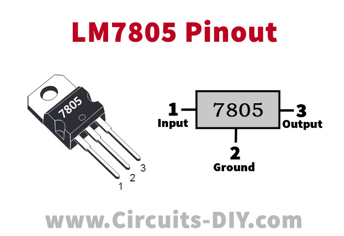
For a detailed description of pinout, dimension features, and specifications download the datasheet of LM7805
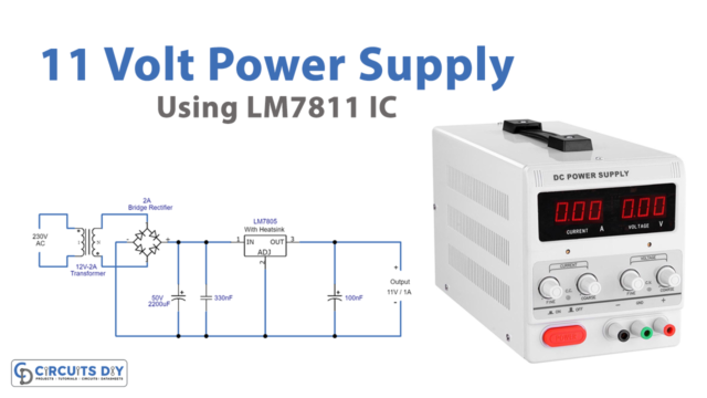
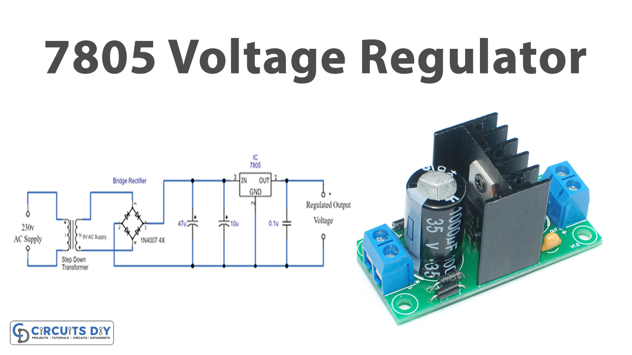
Voltage Regulator Circuit
Working Explanation
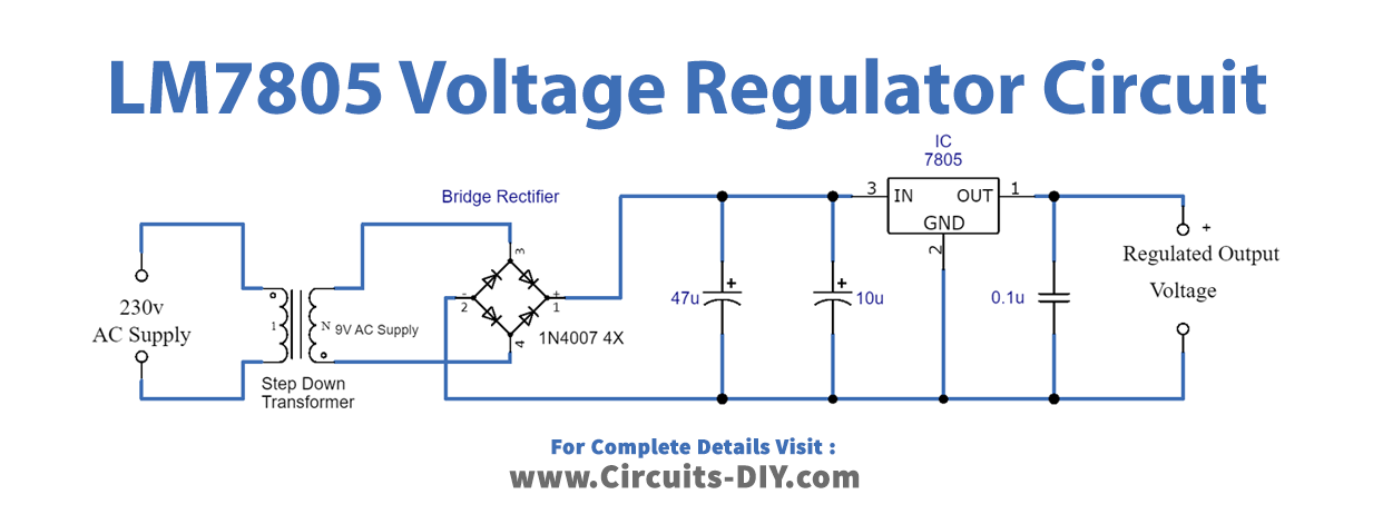
To understand the 7805 IC Circuit Diagram, we have created the circuit using the AC supply. Firstly, with the help of a stepdown transformer the 230 volts of AC supply get converted into 9V of AC. For this purpose, we have connected the primary side to the AC supply and the secondary side to the circuit. Now, this AC voltage can get rectified by the bridge rectifier, wired to our circuit. This bridge rectifier is made of simple electronic diodes. Hence, It converts the AC voltage into the DC voltage. But still, it may have ripples. So, we have connected the capacitors to filter that coming DC voltage.
The output of the filters capacitor is supplied to the IC L7805. Since there are three pins of the IC. Pin 1 takes the filtered input, while pin 2 is for the ground. Now the Ic regulates the voltage and provided the output at pin 3. Pin 3 is wired with the capacitor C3 which is there to remove distortions. Use the multimeter to check the 5V supply across the capacitor.
Application and Uses
- Firstly, the 7805 IC can be utilized as an adjustable Output Regulator.
- Further, it can be used in any circuit that needs a regulated supply of 5V.
- Also, It may work as the current limiter for several electronic applications.
- Moreover, it can be used as a Regulated Dual Supply.