

Introduction: Getting to Know the "Professional ILC8038 Function Generator DIY Kit"


I was casting about for some new electronics projects when I came across a cute little function generator kit. It’s billed as the “Professional ILC8038 Function Generator Sine Triangle Square Wave DIY Kit” and is available from a number of vendors on eBay for 8 to 9 dollars (figure 1).
Figure 1. The Little Function Generator
It’s built around the Intersil ILC8038 waveform generator chip as the name implies. It’s a newer iteration of a function generator kit that’s been available from eBay or Amazon for a while. It looked interesting enough that I ordered one. First issue – the kit ships from China so there was the usual several weeks delay before I got it, but it did arrive in the time frame indicated.
The kit arrived intact and complete. The components all appeared genuine and the PCB and acrylic case were well made. Then I got to the instructions – BIG FAIL. The instructions, such as they were, looked like they were copied and reduced to fit on 5.75 x 8” piece of paper, which made many of the lines unintelligible (plus the fact they were written in pigeon English). The same three sections (sections 3,4 and 5) were printed on both front and back of the “instruction” sheet, no Section 1 or 2. This was unfortunate, because there was nothing to show which component value fit in which holes on the PCB .
I have written this Instructable for anyone with similar issues or other problems, or who is considering building this fine little kit. Step-by-step instructions are included not only for assembly but also use of the ILC8038 function generator.
Supplies
One or more "Professional ILC8038 Function Generator DIY Kits"
An Oscilloscope.
A soldering iron and the usual assortment of small electronics tools (tweezers, screw drivers, etc.).
Step 1: How to Put It Together?


Many of the components can be intuitively placed by looking at the diagrams on the PCB (figure 2).
Figure 2. Printed Circuit Board
The barrel jack (JK1), 3 position terminal strip (JP3), IC sockets, jumper strips (JP1 and JP2), ICs U1 and U2, trimpots (R2 and R3), and the electrolytic capacitors can be placed with certainty, but the resistors, ceramic capacitors, ICs U3 and U4, and potentiometers (one has a different value than the other 3) are going to present a problem. If you have a sharp eye you may be able to read the designations of ICs and the color codes of the resistors in Figure 1. What we really need is better instructions or a good schematic. I was not able to find any good instructions on the internet, but I did find an image of a Chinese schematic. Fortunately, electronic symbols are pretty much universal and component values were in English (figure 3). ICs U2 and U4 were missing but I could pretty much fill in the gaps. I made a bill of materials (BOM), matching PCB components with their appropriate values, which is all you really need to assemble the kit. The BOM is included at the end of this Instructable.
In addition to the schematic and list of materials I have also provided step by step instructions on assembly and operation of this cool little function generator, so let’s get to it.
Figure 3. Schematic
Step 2: Kit Assembly

1. Solder in all the inert components (IC sockets, jacks, jumpers, and terminals). Make sure the notch on the end of each IC socket aligns with the notch in its PCB diagram.
2. Solder the resistors, trimpots, and potentiometers. Be careful to get the 50kΩ potentiometer in the R5 position (AMP). The other potentiometers are all 5kΩ.
3. Solder the capacitors. The negative lead of each electrolytic goes through the hole in the shaded or hatched side of its PCB diagram.
4. Solder in IC U2 (WS78L09) and snap the other 3 ICs into their appropriate sockets, aligning the notches correctly.
5. (Optional step) Remove any excess rosin flux from the solder points with 95% ethanol (Everclear) or 99% isopropanol followed immediately by a distilled water rinse. Be sure to dry the board COMPLETELY before use.
6. That’s it. Assembly is finished.
Now for the acrylic case.
The protective paper peels off easily if each piece is soaked in hot water for a minute or two. The pieces don’t need to be glued together. (I did attach the two longer side pieces to the bottom with a little acrylic cement). Once all the tabs on the side pieces are seated in the slots of the top and bottom plates the four long screws provided will hold everything together.
The short 3Mx5mm screws and nuts are provided to attach the PCB to the bottom plate of the case. The screws are not long enough. I used 8mm screws initially, but then decided not to attach the PCB at all. It fits snugly in the case.
I opted not to remove the protective paper from the top plate of the case since it was printed with labels for the potentiometers, jumpers, and terminal strip (figure 4).
Figure 4. Assembled Kit
Step 3: Operation


I used a small AC/DC adapter that provided 12 VDC/500mA to power the function generator. Don’t use anything higher than fifteen volts. My kit came with the frequency range jumper set to 50 - 500Hz and waveform jumper set to SIN. The other position was marked TAI but I suspect this was a misprint and should have been TRI for triangle.
Sine Wave
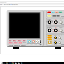
Plug the oscilloscope lead into the SIN/TAI position of the terminal strip and set the waveform jumper to SIN. I used the 50-500Hz range for most of the demonstrations below. I output a sine wave with P-P amplitude of ~5V and frequency of 100Hz using AMP (R5) and FREQ (R4). You may have to play around with the settings a bit until you get a trace on the oscilloscope. Adjust the two trimpots (R2 and R3) and then the DUTY potentiometer to optimize the shape of the sine wave. R2 modifies the top peak and R3 modifies the bottom peak of the sine wave. DUTY (R1) adjusts the left and right bias of the waveform. The first sine wave I generated is shown in figure 5. Not too bad. You can even calculate root mean square voltage if you are so inclined.
(Vrms = Vp-p * 0.35355). It is 1.77 volts for the sine wave in figure 5.
Figure 5. Sine Waveform
Frequency Check (optional)
The next thing I did was measure the maximum and minimum values I could get at each of the frequency ranges.
The results were:
5 Hz to 50Hz range: minimum 1Hz, maximum 71Hz
50Hz to 500Hz range: minimum 42Hz, maximum 588Hz
500Hz to 20kHz range: minimum 227Hz, maximum 22.7kHz
20kHz to 400kHz range: minimum, 31kHz, maximum 250kHz
Minimum for the 500Hz to 20kHz range and maximum for the 20 to 400kHz range were off from the printed values, but most everything else was in the ballpark.
Triangle Wave
Set the waveform jumper to TAI (TRI) and connect the oscilloscope to the TAI/SIN position of the terminal strip. The function generator produces good looking triangle waveforms with sharp peaks (figure 6).
Figure 6. Triangle Waveform
RAMP (Sawtooth) Wave
A reverse ramp wave can be obtained from a triangle wave by turning the DUTY potentiometer counterclockwise. I was not able to get a normal ramp wave by turning the potentiometer the other way. The signal was lost by turning the dial too far, so the leading edge of the wave was never quite perpendicular, and the descending part of the ramp showed a little concavity. Not a perfect sawtooth, but it is what it is (figure 7).
Figure 7. Ramp (Sawtooth) Waveform
Square Wave
Connect the oscilloscope lead to the middle position of the terminal block marked SQU to output a square wave (figure 8). The AMP (R5) and OFFSET (R6) potentiometers seemed to have no effect on the square wave. The voltage of the waveform produced was about the input voltage (12 volts). I should have removed the waveform jumper altogether to see if that improved things but that thought just now came to me.
Figure 8. Square Waveform
Duty Cycle
The duty cycle of the square wave can by changed with the DUTY potentiometer (R1), Turn the dial counterclockwise to shorten and clockwise to lengthen the duty cycle. There is a minor problem with DUTY. Changing the duty cycle also slightly changes the frequency, so it may have to be readjusted after the duty cycle is changed.
Duty Cycle = percent of time in the high state divided by the period of the square wave.
As an example, the square wave in figure 9 has a period of 10msec and is in the high state for 5msec (also in the low state for 5msec).
So, duty cycle = (5msec /10msec) *100 = 50%. Figures 10 and 11 show the duty cycle adjusted to 60% and 40%, respectively.
Figure 9. Duty Cycle = 50%
Figure 10. Duty Cycle = 60%
Figure 11. Duty Cycle = 40%
Step 4: That's All, Folks
That’s about it for this Instructable. If you found it useful, go forth and build your own pocket function generator. You can have a lot of fun for 8 or 9 USD. Simple Circuit signing off.
Step 5: ILC8038 Function Generator Bill of Materials (BOM)
Resistors
R1 Potentiometer 5kΩ DUTY
R2 Trimpot 100kΩ
R3 Trimpot 100kΩ
R4 Potentiometer 5kΩ FREQ
R5 Potentiometer 50kΩ AMP
R6 Potentiometer 5kΩ OFFSET
R7 Resistor 1kΩ
R8 Resistor 1kΩ
R9 Resistor 10kΩ
R10 Resistor 10kΩ
R11 Resistor 4.7kΩ
R12 Resistor 30kΩ
R13 Resistor 10kΩ
R14 Resistor 4.7kΩ
R15 Resistor 10kΩ
R16 Resistor 10kΩ
Integrated Circuits
U1 ICL8038 CCPD Precision Waveform Generator
U2 WS 78L09 Positive Voltage Regulator
U3 18MDSHY TL082CP JFET-Input Operational Amplifier
U4 7660S CPAZ Voltage Converter
Capacitors
C1 Ceramic 100nF
C2 Ceramic 100nF
C3 Ceramic 100pF
C4 Ceramic 2.2nF
C5 Ceramic 100nF
C6 Ceramic 1µF
C7 Ceramic 100nF
C8 Ceramic 100nF
C9 Ceramic 100nF
C10 Electrolytic 100µF
C11 Electrolytic 10µF
C12 Electrolytic 10µF
Jack, Jumpers, and Terminal
JK1 Barrel Jack
JP1 2 position jumper block TAI (TRI), SIN
JP2 4 position jumper block 5-50Hz, 50-500Hz, 500Hz-20kHz, 20kHz-400kHz
JP3 3 position terminal block GND, SQU, SIN/TAI (TRI)


