

Introduction: LM317 Adjustable Voltage Regulator


Here we would like to talk about adjustable voltage regulators. They require more complicated circuits than linear. They can be used to produce different fixed voltage outputs depending on the circuit and also adjustable voltage via potentiometer.
In this section we will first show specifications and pinout of the LM317, afterwards we will show how to make three different practical circuits with LM317.
To finish the practical side of this section you will need:
Supplies
- LM317
- 10 k Ohm Trimmer or Pot
- 10 uF and 100 uF
- Resistors: 200 Ohm, 330 Ohm, 1k Ohm
- 4x AA Battery Pack 6V
- 2x Li-Ion Battery 7.4V
- 4S Li-Po Battery 14.8V
- or a Power Supply
Step 1: Pinout Overview

Starting from the left we have an adjust (ADJ) pin, between it and the output (OUT) pin we set up the voltage divider which will determine the voltage output. Middle pin is the voltage output (OUT) pin which we have to connect with a capacitor to provide stable current. Here we have decided to use 100 uF but you can choose to use lower values as well (1uF > ). Rightmost pin is the input (IN) pin which we connect with the battery (or any other power source) and stabilize the current with a capacitor (here 10uF, but you can go as low as 0.1 uF).
- ADJ Here we connect the voltage divider, to adjust the output voltage
- OUT Here we connect the power distribution circuit input (any device that we are charging).
- IN Here we connect the red wire (plus terminal) from the battery
Step 2: LM317 3.3 V Circuit
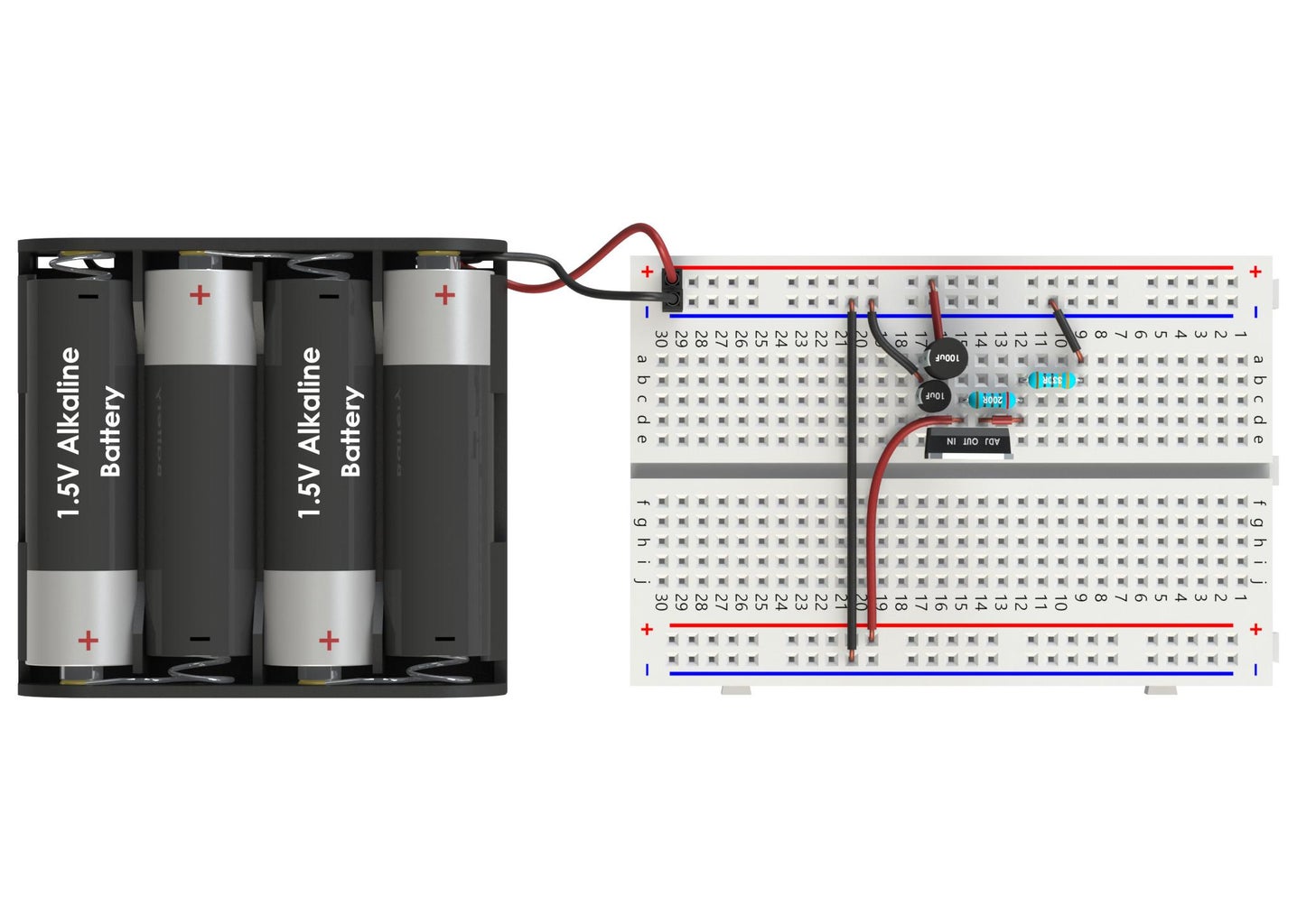
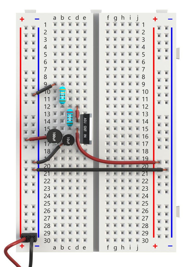
We are now going to build a circuit using LM317 which will output 3.3 V. This circuit is for fixed output. The resistors are chosen from the formula which we will explain later.
The wiring steps are as follows:
- Connect the LM317 to the breadboard.
- Connect the 10 uF capacitor with the IN pin. If you are using electrolytic capacitors be sure to connect the - to the GND.
- Connect the 100 uF capacitor with the OUT pin.
- Connect the IN with the plus terminal of the power source
- Connect the 200 Ohm resistor with the OUT and ADJ pins
- Connect the 330 Ohm resistor with the 200 Ohm and the GND.
- Connect the OUT pin with the plus terminal of the device you would like to charge. Here we have connected the other side of the breadboard with the OUT and GND to represent our power distribution board.
Step 3: LM317 5 V Circuit


To build a 5 V output circuit using LM317 we need only to change the resistors and connect higher voltage power source. This circuit is also for fixed output. The resistors are chosen from the formula which we will explain later.
The wiring steps are as follows:
- Connect the LM317 to the breadboard.
- Connect the 10 uF capacitor with the IN pin. If you are using electrolytic capacitors be sure to connect the - to the GND.
- Connect the 100 uFcapacitor with the OUT pin.
- Connect the IN with the plus terminal of the power source
- Connect the 330 Ohm resistor with the OUT and ADJ pins
- Connect the 1k Ohm resistor with the 330 Ohm and the GND.
- Connect the OUT pin with the plus terminal of the device you would like to charge. Here we have connected the other side of the breadboard with the OUT and GND to represent our power distribution board.
Step 4: LM317 Adjustable Circuit


The circuit for adjustable voltage output with LM317 is very similar to previous circuits. Here we instead of the second resistor use a trimmer or a potentiometer. As we increase the resistance on the trimmer the output voltage increases. We would like to have 12 V as a high output and for that we need to use a different battery, here 4S Li-Po 14.8 V.
The wiring steps are as follows:
- Connect the LM317 to the breadboard.
- Connect the 10 uF capacitor with the IN pin. If you are using electrolytic capacitors be sure to connect the - to the GND.
- Connect the 100 uF capacitor with the OUT pin.
- Connect the IN with the plus terminal of the power source
- Connect the 1k Ohm resistor with the OUT and ADJ pins
- Connect the 10k Ohm trimmer with the 1k Ohm and the GND.
Step 5: Voltage Calculator

We would now like to explain a simple formula for calculating the resistance we need to get the voltage output we would like. Note that the formula used here is the simplified version, because it will give us good enough results for anything that we would be doing.
Where Vout is output voltage, R2 is the “end resistor”, the one with larger value, and the one where we put the trimmer in the last example. R1 is the resistor which we attach between OUT and ADJ.
When we calculate the necessary resistance, first we find out which output voltage we need, usually for us that would be 3.3 V, 5 V, 6 V or 12 V. Then we look at the resistors which we have and pick one, this resistor is now our R2. In the first example we have chosen 330 Ohm, in the second 1 k Ohm and in the third 10 k Ohm Trimmer.
Now that we know R2 and Vout we need to calculate R1. We do that by rearranging the above formula and inserting our values.
For our first example the R1 is 201.2 Ohm, for the second example R1 is 333.3 Ohm, and for the last example at maximum 10 k Ohm R1 is 1162.8 Ohm. From this you can see why we have chosen these resistors for those output voltages.
There is still a lot to be said about this, but the main point is that you can determine the resistor you need by choosing the voltage output and selecting R2 depending on what kind of resistors you have.
Step 6: Conclusion
We would like to summarize what we have shown here, and show some additional important attributes of the LM317.
- Input voltage of the LM317 is 4.25 - 40 V.
- Output voltage of the LM317 is 1.25 - 37 V.
- Voltage drop down is about 2 V, meaning that we need at least 5.3 V to get 3.3 V.
- The maximum current rating is 1.5 A, it’s highly recommended to use a Heat Sink with the LM317.
- Use LM317 to power up controllers and drivers, but switch to DC-DC converters for motors.
- We can make a fixed voltage output by using two calculated or estimated resistors.
- We can make an adjustable voltage output by using one calculated resistor and one estimated potentiometer
You can download the models used in this tutorial from our GrabCAD account:
You can see our other tutorials on Instructables:
You can also check Youtube channel that is still in the process of kicking off:


