

Introduction: Make Your Own H-Bridge Circuit for Inverters


Hello everyone!
Thank you for stopping by this article on making a H-Bridge circuit for converting DC voltages to AC voltage.
This simple yet effective setup is very useful in inverter applications where we need to convert high voltage DC to 50 or 60 Hertz AC signal that can be used to drive out AC loads. Such H bridge is quite common in relatively cheap modified square wave inverters though this can also be used in pure sine wave inverters with appropriate modifications.
Lets move ahead with the theory and building this circuit
Supplies
- IRF840 N channel MOSFETs - 4
- MPSA42 or 13003 NPN BJT - 2
- FR107 or UF4007 diode - 2
- 1N4148 general purpose diode - 4
- 47uF-25V electrolytic capacitor - 2
- 4.7K resistor - 2
- 2.2K resistor - 2
- 10K resistor - 2
- 22R resistor - 4
- 1MegaOhm resistor - 1
- 0.1uF/400V film capacitor - 1
- 2 pin Screw terminal - 2
- Soldering kit and accessories
- PCB making items or verodoard ( depends upon how you want to make it)
Step 1: The Theory

I would like to briefly describe the working principle of the H bridge:
H-bridge consists of 4 switches (which are MOSFETs in our case. They can also be transistors) which can be individually controlled in such a was that the voltage across the load changes polarity after each half cycle of the control signal which is being used to sequentially drive the switches. This creates the required AC waveform from a static DC supply. Note that for this to work, the diagonal switches needs to be operated simultaneously and after one half cycle is over, the other diagonal pair is active.
This briefly explains what the H bridge is.
Now coming another concept of bootstrapping:
Simply put, it is a method to drive the High side MOSFETS properly with the help of a temporary storage element like a capacitor and with some very intelligent connections, we are able to properly turn on the high side mosfet properly so that we do not have any switching loss.
I will explain the switching pattern step by step:
- We have 2 control signals controlling the 2 diagonal pairs of MOSFETs. These two signals are complementary to each other ( when one is active high the other is low and vice versa)
- Suppose one signal ( OUT1 for example) is high- In this case the the LOW side MOSFET connected directly with the signal is turned ON and the BJT transistor is also turned on which pulls the gate pin of the high side MOSFET to ground thus turning it OFF. During this cycle the electrolytic capacitor gets charged via the diode to approximately 11.5 volts ( supply voltage of 12V minus the diode voltage drop).
- In the next cycle, OUT1 becomes low and thus turns OFF the low side MOSFET. During this time, the high side MOSFET is turned on by the voltage that was across the capacitor.
- The same thing happen on the other pair of high side and low side MOSFETs and since OUT 1 and OUT2 signals are complimentary in nature, the H bridge works perfectly fine, turning ON each pair of diagonal MOSFETS in every half cycle.
I hope this explanation made sense. For a detailed explanation, please do not miss out my video where I have explained the concept in proper detail.
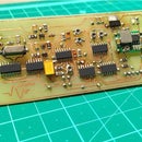
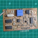
Step 2: PCB Design and Fabrication


I have used the popular easy EDA software to design the schematic as well as PCB layout of my project and then used the toner transfer method to my PCB. You can also used a simple Veroboard to make your circuit.
Some points to note here are that you need to keep your power traces thick so that it can handle significant amount of current.
With the PCB fabrication process complete, I went ahead and soldered all the components which took me about an hour to complete. You can see the pictures of PCB layout and the complete PCB after all parts have been soldered.
Step 3: The Control Card


With the H bridge now complete, it is now time to discuss about generating the control signals tat will drive the gates of the MOSFETs.
For this I will be using my very own TL494 modified square wave card which can generate control signals for 50Hz modified square wave inverter. The deadtime and waveform can be adjusted using the potentiometer and the frequency is crystal controlled so it will remain super accurate every time !
If you want to learn more about this control card then you can visit my website here:
https://utsavrshah.in/Sensors%20and%20modules%20re...
Please share your feedback on this module and I would love to hear any improvements that you can suggest.
Step 4: Testing the Gate Signals


With the control card in place it is very essential to check that all the 4 MOSFETs are receiving the correct gate drive signals which is very important because we will be using this MOSFETS to switch high voltage DC and in absence of the correct gate signals, the MOSFET can have huge power dissipations and even short the complete H bridge.
Here I have used a 12V source to power the control card and used my mini oscilloscope to evaluate the gate signals on the high side as well as the low side MOSFETS and after getting satisfactory results, I moved on to the next step.
Step 5: The High Voltage DC Source


Since this H bridge is used for inverter applications, it will switch high voltage DC to 50Hz AC and for this I had previously made a high voltage DC-DC converter that will convert 12V DC from a typical lead acid battery to about 300V DC. This output voltage is adjustable and remains stable due to active feedback circuit.
Over here you can see that we are getting stable DC voltage of about 230 volts which will be required for our application.
I also have a detailed tutorial for this DC to DC converter up on my website:
Step 6: Getting Everything Connected


Now that we are ready with the modules. We can now connect the high voltage output of the DC to DC converter with the input to the H bridge.
Both the DC to DC converter and the H bridge control circuit is powered from the 12V of the lead acid battery.
Step 7: AC Load Test and Waveform Evaluation


I would explain my setup here for testing my H bridge with the AC load:
For the AC load I have used a small table fan which I feel is an ideal test load for this application.
The high voltage DC is fed to the H bridge to convert it into modified square wave AC of 50Hz frequency which is being used to power the fan and also a small step down transformer that is used to lower the AC voltage to acceptable levels for my oscilloscope that will be used to evaluate the waveform when the load is running and also without load.
As you can see that the waveform is quite stable and maintains its characteristic shape with a slight distortion which can be easily filed with a capacitor which I had added later.
I ran the test for 15 minutes with continuous operation and observed no heating.
Step 8: Efficiency and Conclusion


As a last step, I hooked up my multimeter in current mode to check the current consumption and then evaluated the overall efficiency.
The overall setup works at about 84% efficiency which is reasonable considering DIY design.
The H bridge works completely fine in this application and I would call this project a success.
One disadvantage of this I bridge though is you can only use this in switching applications and not in static applications like constantly driving a motor in a particular direction, this is because with time the bootstrap capacitor looses charge and eventually is not able to drive the high side MOSFET until the signal is switched again. Apart from this, this design is a good one.
I hope you like this article and would love your feedback on this. Please do not forget to share this project with others and do not miss out on the detailed video in the beginning of this tutorial and while you are there please drop in a like and also consider subscribing to my channel if you like my content.
Till then, see you in the next one!


