

Introduction: Thinkpad W701DS Lattepanda Alpha + KVM Conversion


This project converts an old Thinkpad W701DS from 2010 and replaces the internal hardware with more modern, faster components. Additionally, the laptop can be used as a KVM switch and similar steps can be used to convert other laptops.
Features:
- Original internals from 2010 have been upgraded to 2018+ components.
- Both the primary and secondary screens can be used internally for the laptop, or externally as external monitors by using the 2 HDMI IN ports. These are controlled by 2 small push button switches on the left side of the laptop.
- Keyboard + trackpoint can also be used for the laptop or externally similar to the screens. This is controlled using a toggle switch on the right side of the laptop.
- Maintains portability by utilizing a 2S3P battery pack.
- Up to 4 simultaneous displays (2 via built in displaylink; 2 via direct connect; primary lcd - direct over hdmi; secondary lcd - displaylink; external usbc - direct connect using displayport alt mode up to 4k 60hz; hdmi out - displaylink up to 4k 60hz).
Specs:
- 17.0" LG 2560x1600 main IPS screen (formerly an old 1920x1200 Samsung RGB panel). The new panel is currently found in the LG Gram laptop
- 10.1" AUO 1920x1200 secondary IPS screen (previously a 1280x768 TN panel)
LattePanda Alpha 864s:
- M3-8100y 2c/4t cpu - About 30% faster in raw performance than the 940xm I had in the machine originally)
- 8gb soldered RAM - Bit small and only single channel, however
- Intel AX210 wifi 6 wifi card using the laptop's built in antennas
- 1TB NVMe SSD
Supplies
Tools:
- 3D printer (I used a Prusa MK3S+)
- 3D printer filament (I used Prusament PETG)
- Soldering station
- Helping hands with magnifying glass or microscope highly recommended
- Set of precision philips and hex screwdrivers (The iFixit toolkit is excellent)
- Multimeter
- Power bench supply or adjustable power brick (I used this)
Manuals:
- w700_w700ds_w701_w701ds_hmm_en_43y9442_08.pdf (thinkpads.com)
- USB_Laptop_Keyboard_Controller/Lenovo ThinkPad T61 USB Keyboard.pdf at master · thedalles77/USB_Laptop_Keyboard_Controller (github.com)
Single Board Computer:
- I Used the LattePanda Alpha 864s - 8GB RAM + 64GB eMMC | DFRobot Electronics for this project. However at this time it is a bit overpriced, and the LattePanda 3 Delta – A Pocket-sized Hackable Computer for Mega Creativity(1) – LattePanda has just been released which is significantly faster and has most of the same I/O at a lower price. I would actually recommend this new Delta 3 instead of the Alpha 864s and if you are willing to make a few modifications which I will mention later in this guide (TODO). Alternatively, there might be an updated Alpha 864s in a year or two which could be a drop in replacement without any need for mods.
Buck/Boost Converters:
- Amazon.com: BULVACK 10 Pack LM2596 DC-DC Buck Converter Step Down Module Power Supply DIP Output 1.25V-30V 3A : Electronics
- Amazon.com: WOWOONE dc to dc Step up Converter DC Voltage Regulator Voltage Converter Step Up dc Boost Converter USB Power Module Supply Module 2V-24V to 5V-28V 2A MT3608 Mico USB (Pack of 10) : Electronics
General Wiring/Screws/Connectors:
- Amazon.com: PH 2.0 Connector Pre-Crimped Cable Kit Compatible with JST-PH2.0mm for Battery JJRC H36 Blade Inductrix Tiny Whoop Arduino mkr1010 MKR Zero and MKR Vidor 4000 (Female&Male Connector&Wire) : Toys & Games (May run out of 2 or 4 pin connectors so might have to buy an additional pack. Can also use your own connectors if you prefer)
- VIGRUE 840 PCS M2.5 x 4/6/8/10/12/16/20/25mm Hex Button and Socket Head Cap Screws Nuts Washers Assortment Kit with Storage Box: Amazon.com: Industrial & Scientific
- 20 AWG Silicone Plug Connector for JST, SIM&NAT 2 Pin Battery Connector for JST RCY Plug Female Male Connectors Wire for RC Toys Battery, 5 Pairs - - Amazon.com
Displays/Connectors/Cables:
- 17" QHD LCD Screen Display LP170WQ1-SPA1 LP170WQ1(SP)(A1) For LG 17Z990 | eBay
- 2K mini HDMI LCD SCREEEN Driver Board kit for LP170WQ1-SPA1 LP170WQ1-SPE1 | eBay - This adapter board in the listing is slightly different from the one I received. Later in the guide I will show you what version I received so you can ask the seller for the same one. If they don't have it anymore, the 3d model mount for the adapter must be modified.
- 5pcs 40Pin 0.5mm pitch LVDS EDP MIPI LCD Screen Cable Connector | eBay
- HD MI LCD Controller Board With 10.1" B101UAN01.A 1920x1200 LCD Screen | eBay
- 40 pin eDP male to male cable - Make sure that the cable uses individual wires for each pin that can be separated. FPC or FFC cables which are made of a single long piece of plastic will NOT work since it cant be routed from the lid to the base of the laptop.
- Amazon.com: 2-Pack Male to Male DC Extension Cord 5.5mm x 2.1mm,12v DC Power Extension Cable for Security Camera,Dvr Standalone LED Strip,Car,CCTV IP Surveillance,5v 9v 24v 12 Volt Plug Supply Adapter 3FT 6FT : Electronics
Power Cables:
Battery Pack:
- Samsung 30Q 18650 3000mAh 15A Battery | INR18650-30Q (18650batterystore.com) - 6x
- Amazon.com: Anmbest 5PCS 2S 7.4V 8.4V 8A 18650 Charger PCB BMS Protection Board for Li-ion Lithium Battery Cell : Electronics
- SHONAN Pure Nickel Strips for High Capacity Battery Packs- 0.15x6mm(3.1 oz, 32 ft/roll) 99.6% Purity Nickel Strips for Battery Spot Welding - - Amazon.com
- 20 AWG Silicone Plug Connector for JST, SIM&NAT 2 Pin Battery Connector for JST RCY Plug Female Male Connectors Wire for RC Toys Battery, 5 Pairs - - Amazon.com
- mankk 6Pcs Rocker Switch 3 Pin SPDT AC 125V/10A 250V/6A ON-Off-ON Toggle Switch with Pre-soldered Wires for Car Boat Trucks M-KCD3-103-X: Amazon.com: Industrial & Scientific
- 10p Battery Connector 0511461000 Molex 1.25MM Pitch Lattepanda Alpha | eBay
- Donor W701DS battery so the cover can be used with the custom battery. Alternatively can 3d print one but I haven't made a 3d model of it.
KVM parts:
- Amazon.com: Club3D CSV-1474 USB 3.0 type A to Dual HDMI 2.0 4K 60Hz External Graphics video adapter for multiple Monitors : Electronics
- Amazon.com: HDMI Switch 4k@60hz Splitter, GANA Aluminum Bidirectional HDMI Switcher 2 in 1 Out, Manual HDMI Hub Supports HD Compatible with Xbox PS5/4/3 Blu-Ray Player Fire Stick Roku (1 Display at a Time) : Electronics - 2x
- Amazon.com: HDMI Coupler 2 Pack, 4K HDMI Female to Female Adapter for Extending HDMI Devices Compatible with HDTV Roku TV Stick Chromecast Nintendo Switch Xbox One Playstation PS4 Laptop PC : Electronics - 2x
- Amazon.com: CY 50pcs Type B Micro USB Female 5 Pin Jack Port Socket Connector Solder Type Repair Parts : Electronics
- Twidec/2Pcs Mini Toggle Switch 4PDT 2 Position 12 Pins ON/ON Miniature Toggle Switch AC 6A/125V 2A/250V Car Boat Switches with Waterproof Cap MTS-402-MZ: Amazon.com: Industrial & Scientific
- Amazon.com: OCR 180Pcs Tactile Push Button Switch 10 Values 6x6mm Micro Momentary Tact Button Switches Assortment Kit : Industrial & Scientific
Keyboard/Trackpoint Conversion:
- 0543630489 Molex | Connectors, Interconnects | DigiKey (I would buy a few just in case if you accidently break one)
- Converter board using the files in USB_Laptop_Keyboard_Controller/Example_Keyboards/Lenovo_ThinkPad_T61/Teensy 3p2 at master · thedalles77/USB_Laptop_Keyboard_Controller (github.com). You can send the files to OSH Park ~ to have them printed which is what I did.
Video/USB Cables:
- Amazon.com: Twozoh Ultra-Thin HDMI to HDMI Cable 1.6FT, Hyper Slim HDMI 2.0 Cable, Extreme Flexible HDMI Cord Support 3D/4K@60Hz, 2160P, 1080P : Industrial & Scientific 4x
- 3' HDMI cable
- Amazon.com: USB 4 Extension Cable 2FT, Right Angle USB4 Thunderbolt 4/3 Extension Cord, PD 100W Fast Charging 40Gbps Data Transfer 8K@60Hz Video, 90 Degree Type C 4.0 Male to Female Extender,for USB C Devices : Electronics
- Amazon.com: Faodzc USB 3.0 Extension Cable 2 ft,Short USB Extension Cable Type A Male to A Female 5Gbps Data Transfer Compatible with Keyboard,USB Flash Drive,Playstation,Mouse,Hard Drive and More : Electronics 2x
Networking:
- Amazon.com: Superbat MHF4/IPEX4/IPX4 to U.FL Cable (10cm/3.9") MHF4 Female to IPX (IPEX/UFL) Male RF Pigtail Cable 1.13MM Low-Loss Extension Cable 2-Pack : Electronics
- Amazon.com: WiFi 6E Wireless Card Intel AX210 NGW Bluetooth 5.3 Tri-Band 5400Mbps Network Adapter for Laptop Support Windows 10/11 (64bit) M.2/NGFF : Electronics (Optional)
Storage:
- M.2 NVMe SSD (Optional). LattePanda comes with 64gb eMMC by default.
Step 1: Important Notes / Helpful Tips
3D Printing:
- There will be mounting brackets and various parts that need to be 3D printed. I used prusaslicer with the following settings:
- .2mm detail quality preset
- PrusaSlicer hard to remove supports – PrusaSlicer – Prusa3D Forum -
- I recommend using a maximum of .2mm layer height since this is what I tested with. Anything bigger may cause the pieces not to fit together. Tolerances unfortunately are tight on many of the parts.
- If a part does not fit correctly, you may need to modify your printer settings or possibly the 3D file itself.
- I advise against printing the parts through a printing service. Because of variations in layer height and precision of my MK3S+ printer, parts printed using a printing service might not fit. For example I printed the secondary display bezel for the laptop and although it fit properly, the same part made by the printing service was way off. Not sure if this was an isolated incident, but I probably wouldn't risk the time or money.
Single Board Computer Selection:
- Lattepanda Alpha 864s - This is what I used for this particular build and everything in this guide is tailored for it.
- Lattepanda Delta 3 - Much faster and recent than the 864s, but lacks a battery connector. I'd actually recommend using this instead of the 864s if you are willing to make some modifications which I will discuss later in the guide.
Always test individual components and cables before and after modifications/installations. This makes it much easier and faster to find and debug issues.
Disclaimer: Working with electronics and electricity can be dangerous. Although I've tried to make this guide as clear and safe as possible, I take no responsibility for any injuries or damages that may occur. Please proceed at your own risk
Step 2: Power Diagram

Step 3: Keyboard Adapter Diagram

Step 4: Display Diagram

Step 5: I/O Diagram

Step 6: Lid Removal and Disassembly
First, we will be replacing the internals of the lid with new display panels and associated mounting hardware + cables. The new components will be:
- 17" IPS main display
- 3D printed hinge bracket supports
- 3D printed top + bottom LCD front + back supports
- 10.1" IPS secondary screen
- eDP to HDMI video converter
- Male to Male DC barrel jack cable
- 3D printed sliding video converter mount
- 3' HDMI cable
- 3' 12v DC extension power cable
The HMM provides a good explanation of removing the lid from the base and disassembling it (and the secondary screen), so I would refer to that.
Step 7: Base Disassembly
Next, we will remove the motherboard and card reader daughter boards from the laptop. You should be left with just the metal frame and usb daughterboard attached together.
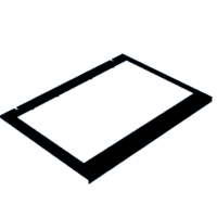
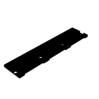
Step 8: Printing the Secondary LCD Bezel

Step 9: Upgrading the Secondary Screen


Once you have the lid and secondary screen taken apart, we can insert the new display, cables, and 3D printed bezel. The new display comes as a kit and has the driver board and video/power cables. I put kapton tape on the video connector to keep it from sliding out. Note the position of the screen on the lid. The custom display bezel has tabs that should surround the edge of the LCD but its easy to accidently push these tabs onto the screen and damage it if the screen isn't positioned correctly.
Step 10: Print Sliding Mount for 2nd Display

Attachments

Step 11: Attach Display Driver Board and Locking Piece to the Sliding Mount

I used 3 screws to attach the driver board to the new sliding mount. There will be 3 cables attached to this board:
- The top left connector is an LVDS connection that goes to the secondary display (included in kit)
- Bottom left connector is for LCD backlight (included in kit)
- Bottom middle is a 4 pin connector for 12v board power, however I actually ended up using the dc barrel jack on the bottom right for power instead
For attaching the metal locking piece, I used 6 screws with washers on the other side to secure it.
The step above shows the placement and how it should look once installed.
Step 12: Install the Sliding Mount for the 2nd Display

There are 4 screws on the top and bottom of the mount that secure it to metal rollers. It is VERY important to check the length of the screws so that they are not protruding and scraping against the lid
Step 13: Lid Cable Management and Prints


There is a 3d printed second piece (made up of 2 pieces) that attaches to the bottom roller. This, in combination with wrapping the cables around the hinge screw posts, holds the cables for the hdmi and 12v power cable such that it extends and retracts without bunching up or pressing against the main display.
I used the 12v dc power extension cable linked in the parts sections, along with a 3' HDMI cable.
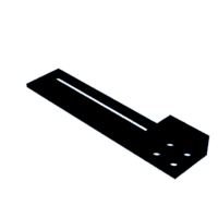

Step 14: Print and Attach the Main LCD Hinge Mounts

Each hinge has a new mounting bracket to help hold the upgraded main display. To attach them, align the holes in the bracket similarly to how the old display was attached to the hinges. I used the existing screws that secured the old LCD.


Step 15: Print and Attach the Main LCD Back Supports

The two bottom back supports use washers with the screws. For the piece at the top, we will be screwing it in later, since the display needs to sit on top, and then another piece will be placed on top to create a "sandwich". Then there will be screws that secure the plastic pieces to the lid.
Note: Seems like the 3d model I had for the top backplate of the LCD is missing. Will upload the file once I make it again.


Step 16: Test the Main LCD Brackets and Supports

After installing the brackets and supports, it would be a good idea to gently place the panel to make sure everything fits snugly.
Note: In this photo I omitted the top backplate for the LCD since it would just fall straight down without the additional bracket on top
Step 17: Preparing Cable for the New Main Display

The main lcd driver board is a kit that comes with a lcd cable that needs to be modified. As you can see in the pic, it uses a 40 pin .5mm pitch flat ribbon cable (white) connected to a 40 pin .5mm to 40 pin .4mm pitch adapter (yellow). This then connects to the display.
The issue here is that the .5mm pitch cable (not the adapter part) is too wide and won't be able to route through the small cutout like the old lcd cable could. To solve this, we need to find a stranded 40 pin .5mm pitch cable or a cable that is made up of individual wires that we can twist together to make it thin.
Carefully remove the black tape on the cable, and you should be able to remove both parts of the cable.
Step 18:


I used a donor cable (red) from another display driver board. It was originally wide/flat, with black tape holding all the wires together. I simply removed it and was then able to bundle the wires. I then soldered a female 40Pin 0.5mm pitch eDP connector (linked in parts list) to the .5mm to .4mm pitch adapter, and then attached all of them together. The final cable was a bit fragile where the parts met, so I recommend wrapping tape around it to secure it.
Step 19: Install and Route the Main LCD Cable

Connect the modified cable to screen, then gently place it on the hinge mounts and route the cables as shown. I used some shielding tape on the red wires to help bundle and organize them.
Step 20: Remove the Motherboard and Daughter Boards
For this step, we can just refer to the HMM on how to remove the motherboard and daughter boards. You can actually leave the front right daughter board in the laptop, however. This is where there are 3 usb ports and a modem jack.
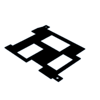
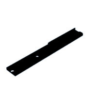
Step 21: Print the Main LCD Driver Board Mount

Note: There are two additional small pieces (not pictured) that attaches to this mount and to the frame of the laptop.

Step 22: Partly Insulate the Main LCD Driver Board With Kapton Tape


Step 23: Install the Driver Board Mount to the Base

Circled in red are the additional pieces from step 21.
Step 24: Mount the Driver Board to the Adapter

Step 25: Create the New Battery

Please be extra careful when handling batteries and only attempt this if you are aware of what you are doing. I take no responsibility for any damages or injury that may occur.
I recommend keeping a bucket of sand nearby and immediately putting electrical tape over any exposed metal surfaces as you are making the battery. This will help avoid accidental shorts which could cause sparks, fires, or explosions.
The battery is in a 2S3P configuration and the above diagram is how the battery is wired.
In order for the battery to be charged by the lattepanda, the battery voltage can't be too low. I am not sure what the exact threshold this is but aim to have at least a 7.5v output on the battery pack. You can manually charge the battery by using a dc charger like this and using the 7.5 voltage setting. To make an adapter for connecting the battery to the charger, you can use the 2 pin 20AWG wires listed in the parts section and attach the exposed wire ends to a DC screw post adapter that comes with the power supply.
Step 26: Solder JST Connectors and Wires to the Buck and Boost Converter
In order to connect to the output and input of the buck converter, we will need to solder wires to the + and - pads of the converter and attach JST connectors to them.
Step 27: Calibrate Buck Converter to Output 5v
There is a potentiometer on the board that we can adjust by turning a small gold colored screw. While the board is powered (we can use the battery pack we made), we can attach a multimeter to the output of the board and turn the screw clockwise or counterclockwise until we get a 5v output.
Step 28: Calibrate Boost Converter to 12v
This step is basically the same as the previous step, but this time we need to adjust the screw of the potentiometer so that the output of the board is 12v
Step 29: Install the 5v Buck Converter

I put electrical tape on the bottom of the buck converter to avoid shorting it with the metal on the laptop's baseplate.
Attachments

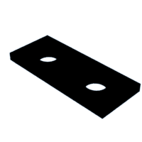
Step 30: Install the 12v Boost Converter

The converter sits sandwiched between 2 plastic pieces. They are then secured to the frame using screws

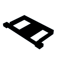
Step 31: Print the Left HDMI/Power/KVM Button Caddy Frame


Note: There is a rear backplate for the caddy (not pictured)


Step 32:

The power switch should sit flush with the power switch backplate (right). The HDMI on/off switch holder (left) will then fit in this backplate


Step 33: Create the 2 HDMI Push Button Switches

Make sure to verify that the pins of the switches are contacting correctly and that you are soldering the two JST connectors to the correct wires. You can use the "Continuity" setting on a multimeter to test this. When I was testing, I found that one of the switches had an intermittent connection.
Step 34: Assemble the Left Caddy


The small black piece basically screws into the HDMI switch holder and prevents the switches from being pushed out of place.

Step 35: Install the Left Caddy Into the Laptop


When routing the cables, we also need to make sure that the black/red power cable routes into the batter compartment of the laptop's base.
Step 36: Solder New Connectors Onto HDMI Switches

The HDMI switchers come with push button switches directly soldered to the boards. We need to remove them and attach JST connectors that will then be able to connect to the push buttons we have on our left caddy from earlier.
Step 37: Insulate the HDMI Switches


I used electrical tape to help insulate the boards from any shorts.
Step 38: Create the "Y" Power Cable Splitter

This cable connects the power from the battery pack to the lattepanda, buck converter and boost converter.
Step 39: Create the Micro Usb Keyboard Connector and LCD Power Toggle Switch

Note: In order for the micro usb to work power and ground must be connected, in addition to regular data- and data+ pins.

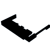
Step 40: Print the Ultrabay Caddy


Step 41: Install the Toggle Switches, USBC, USB3.0 Cables to the Caddy


The red arrow points to the plastic clamp on the USBC cable. This prevents the cable from moving when another cable or device is plugged into it.
Step 42: Install the Micro USB Splitter

The black rectangular piece of plastic goes in between the ultrabay faceplate and the rear main backplate. It helps hold the micro usb connector in place.
Step 43: Install the DisplayLink Board and HDMI Cables

Step 44: Slide the Right Caddy Into the Laptop

Step 45: Create Micro Usb Cable
This cable will be used to connect the micro usb cable from the ultrabay to the lattepanda's USB 2.0 header we made earlier.
Step 46: Install the Lattepanda + Mount


You will need to attach the wifi extension/adapter cables to the existing antennas in the display, and then to the lattepanda. I wrapped shielding tape around each end of the extension/adapter cables, followed by electrical tape on top (blue section for example). The red arrow points to the lattepanda's USB 2.0 header. I just used some angled header pins and soldered some wires to them.


Step 47: Modify and Reinstall the Keyboard Bezel

In order for the keyboard bezel to fit, I had to remove a piece of plastic where the HDMI cable sits on top of the metal frame
Step 48: Remove the Bottom Plate From the OEM Battery


Using a razor, very carefully pry the baseplate off of the original battery. There are seams between the baseplate and top housing of the battery meet.
Step 49: Install the New Battery

The two pin JST power connector from when we installed the left caddy should already be routed into the battery compartment. We just need to connect it to the battery's connector, place the battery pack inside, and attach the cover
Step 50: Install the Keyboard, Palmrest
Step 51: Screw in Palmrest, Keyboard, Keyboard Bezel
When installing back the screws for these three pieces, double check that no wires are in the path of the screws. Also do NOT tighten screws all the way. Only tighten until a snug fit. The motherboard would have originally been sandwiched between the frame and the different pieces, but since we aren't using that anymore there will be a 2-3mm gap.
I had tried creating plastic washers to fill this space, but they were very difficult to keep in place when trying to screw in the screws. I also found that they weren't really necessary since the thickness of all the wires provided some resistance to prevent plastic pieces from bowing in. Additionally, the mounts for the lattepanda, buck/boost converters, and driver boards fill a lot of these gaps.
Lastly, for the palmrest you may need to press it up against the base of the laptop a little depending on if the wires underneath it are too bunched up


