Overview
For those of you following along at home, you no doubt have already read my “First Looks” Review. I include a good deal of history in that article, which you may find here.
As I mention in that article, the kit is one of a long line of Hasegawa Stukas. The moldings have been engineered to adapt to virtually every Stuka version. The R-2 is basically a B with the only discernible difference being the external long range tanks. They come on a separate sprue along with the special “snake” decals. Otherwise, along with the eleven unused parts, you could model any number of B or C versions.
So now we’ll just go into the build (with a few exceptions regarding the color scheme and markings which I will touch on later).
The Build
Since I was given this kit with the express purpose of writing a review, I decided from the start to build the kit out of the box and by the directions – two things I seldom do and probably won’t do again for reasons which will soon become apparent.
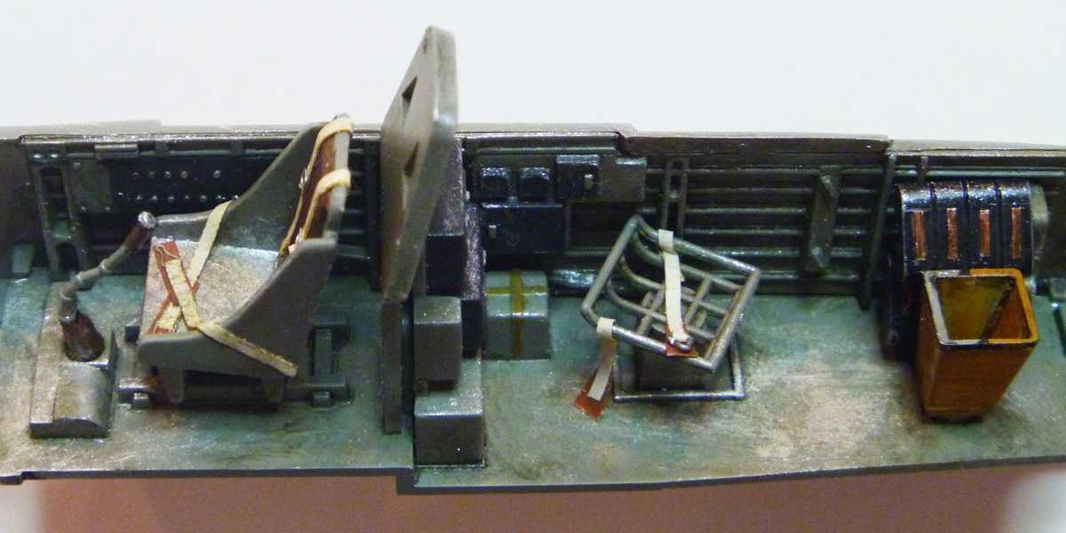 As usual, cockpit assembly is step 1. The cockpit floor and seats, etc., comprise seven parts and represent some nice detail. After basic painting and weathering with oil wash and dry brushing, I highlighted the dials and controls on the radio equipment and made Tamiya tape seat belts and harnesses with wire buckles (tediously wrapped around the end of an X-acto knife to bend them into a more or less buckle-like shape). So far, that’s the only non-out-of-the-box addition, but an important one to say the least. Of course, for the really picky modeler, there are plenty of aftermarket alternatives.
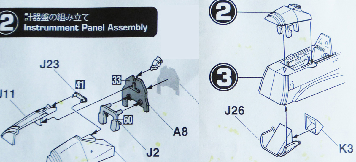 The next rather unusual step involves the instrument panel, gun sight and rudder pedals that form a unit, which then is suspended from the upper deck which sets atop the forward fuselage. I know, sounds confusing. At first I couldn’t figure out what the things were hanging from the instrument panel, but when they were inserted it became clear: rudder petals that leave the space below them open to the floor and the target-finding window.
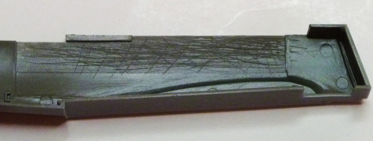
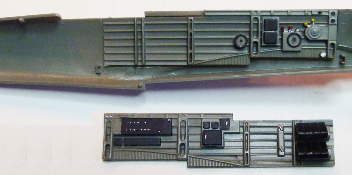
The insides of the fuselage halves have been scored and cut out in a rather crude way to accept the side consoles.
Next came the propeller. Six parts: spinner, base, three blades and a cap. The base includes a shaft that inserts through a whole in the engine cowling face to be held in place by the cap. This is another thing I would never do. Usually I would create some arrangement that would let me attach the propeller last like the way Tamiya includes a polypropylene washer so the prop can be inserted and pulled off again at any time. That keeps it out of the way and gives me a nice ‘finishing touch’ at the end of the build. Unfortunately in this case, the shaft is lose enough that just fitting it through the whole will not keep it in place, requiring the glued on cap to secure it. Not my druthers, but again, I stuck to the instructions.
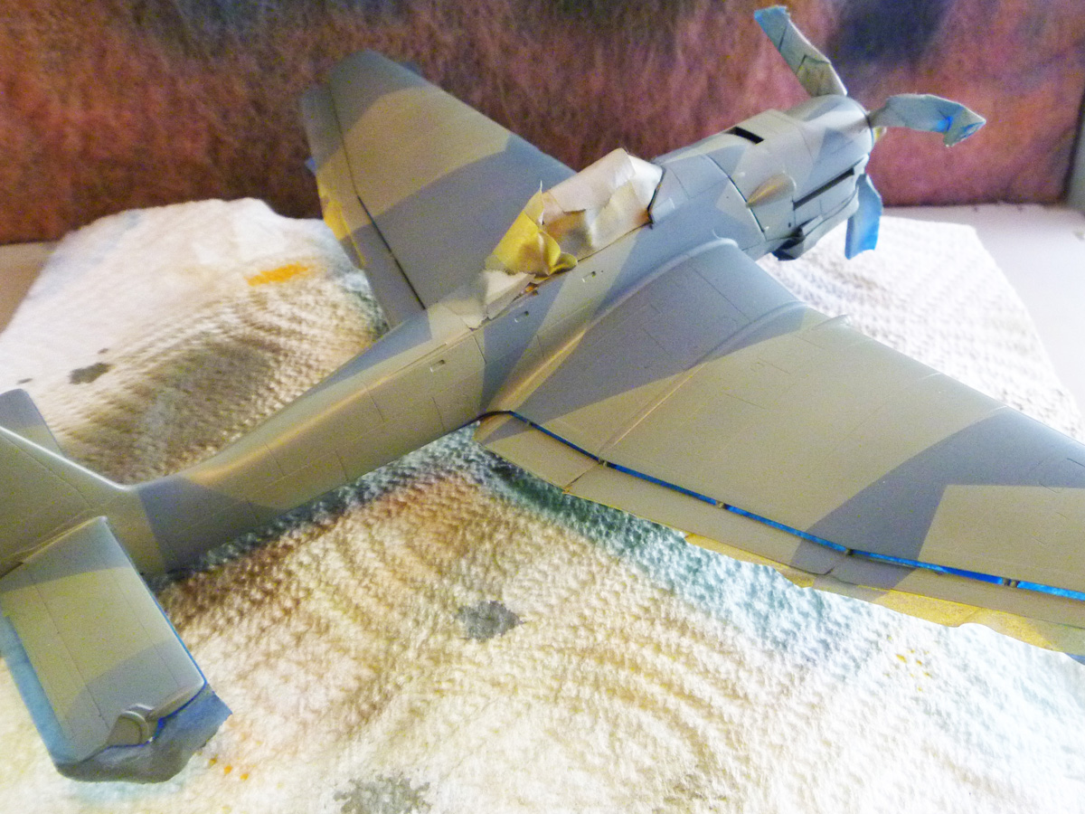
After the fuselage has been buttoned up, the upper decking with instrument panel, etc. is dropped on top and the lower section of the forward fuselage attached. This lower half houses the cockpit floor window which is a triangular glazing that fits into that assembly – or at least it’s supposed to. I tried putting it together as shown, but could not get it to fit. I tried doing it upside down, right side left, inside out, nothing fit! I checked other build reviews but no one mentioned this problem. Either they had no problem, they’re keeping it a secret or I’m an idiot. Wait – don’t answer that. In the end I just said “screw it” and left it off. It’s in about the least visible place it could be. I don’t think it will be noticed, so don’t tell anyone. (By the way, the profile of the fuselage without the canopy, wing or tail feathers, bears a striking resemblance to nothing less than a menacing serpent.)
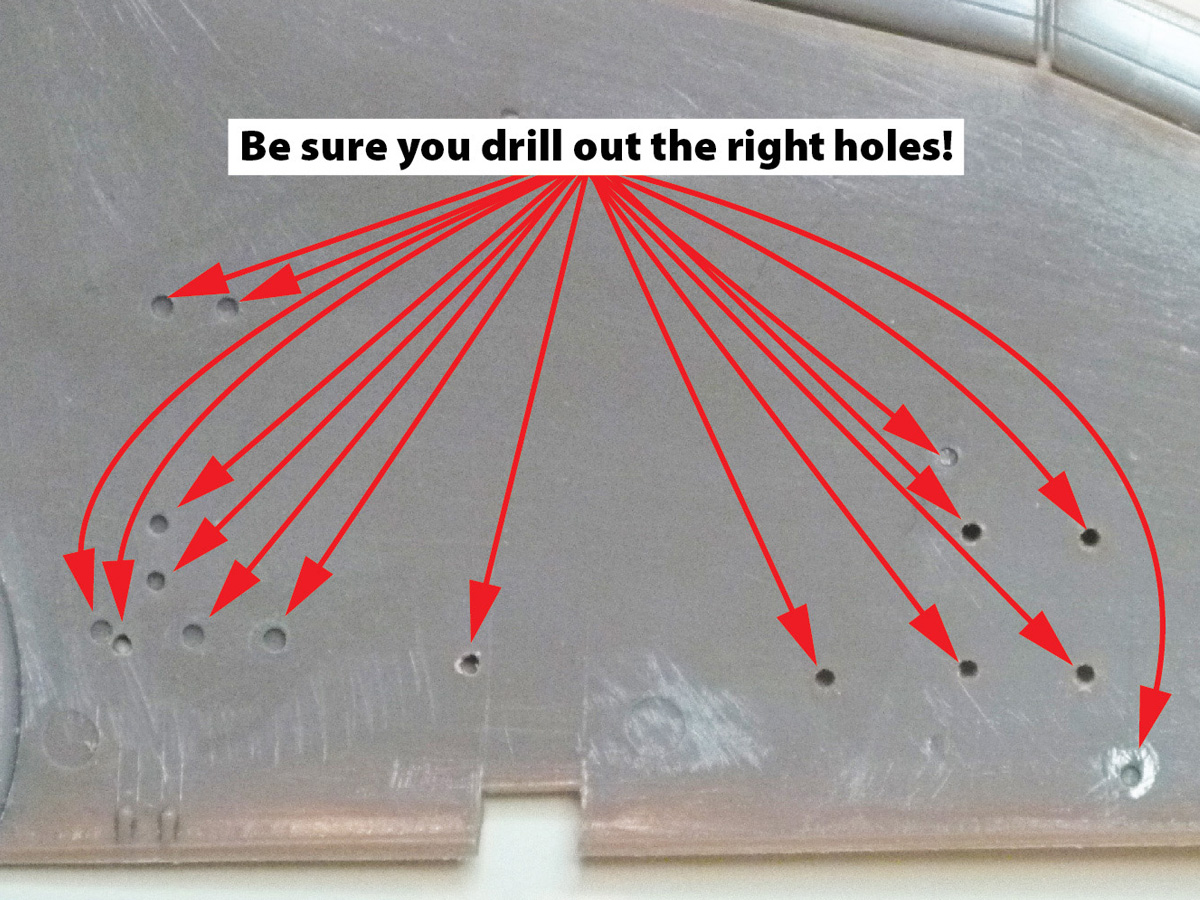
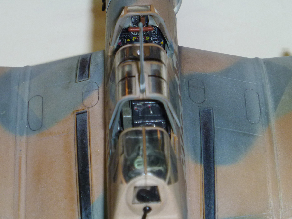
The wing assembly is straightforward. The lower wing and ailerons/flaps (the signature engineering hallmark of Prof. Hugo Junkers’ aircraft of the period) are molded as one piece with the right and left upper wings glued on top. But before gluing them together, be sure to drill out the correct holes for whatever stores you plan to attach.
One concern I had with the wing: on dry fitting it seemed that there would be a gap on either side along the top. Nothing unusual, but it would take some filling. I considered a technique I have heard of but never tried: gluing the top wings to the fuselage then gluing that assembly to the lower wing. That would insure a tight upper wing-fuselage fit, but again I opted to follow directions and glue the wings separately. Turns out I needn’t have worried: the wing fuselage joint was hardly noticeable. A tiny bit of putty and we’re good.
The engine unit glued on front, the tail feathers attached and the big work is done. A deck panel on the rear fuselage behind the gunner’s seat completes that construction step. Unfortunately it covers up half the rear compartment burying my work there for all eternity.
Next comes the landing gear. Two simple wheel pants halves enclose the two wheel halves. I did paint the wheels before installing them, but this is where following instructions left me with a real headache which I’ll explain later. Even so, at the next part of this step, I had to depart from the instructions: I was not about to attach all the fiddly bits such as tail plane braces, dive brakes, aileron balances, etc. - too much handling yet to be done!
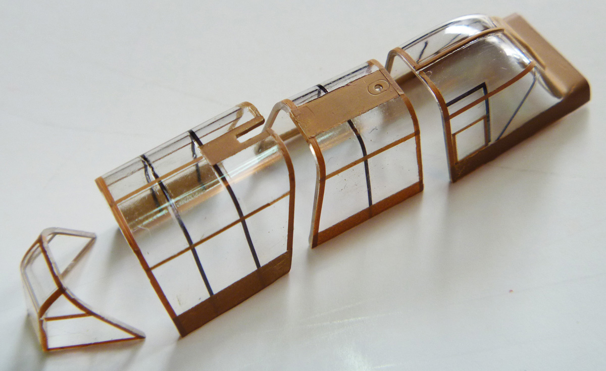
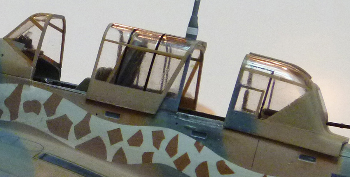
The last step in the instruction (step 15) is the canopy. This was a real challenge: not just because it’s a typical 30’s style ‘greenhouse’. The framing is unique. Several of the frames are actually inside the canopy.
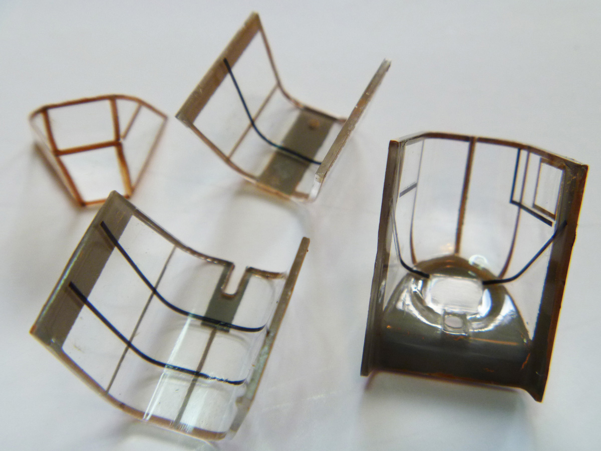
After a great deal of fussing, I succeeded. Mostly. I had one frame that fell apart in the middle canopy but I was able to touch it up with a fine point marking pen and luckily, the open pilot’s canopy will hide that. Since I was at it, I decided to use decal film to do the framing on the outsides as well. I figured this would be the easy way to address the faint framing lines scribed in the canopies that would make my usual routine of masking the sections with Tamiya tape and carefully slicing away the excess along the raised frames. There literally are no raised frames here. I sprayed a strip of clear decal film with inside RLM 02 with a topcoat of lightened RLM sand yellow then cut very thin strips with a fresh blade. Making sure I had plenty of length to work with, I then laid the strips into position and lightly pressed them down with a cotton swab.
At this point I realized that some of the splinter camouflage would be visible on the rather wide lower frames. If the camouflage is all one color, I usually do the canopy separately and install it at the end, such as the instructions indicated and as I was intending to do here, but now I would have to match the patterns on the frames after the fact meaning more masking. Almost certainly any tape – even Tamiya tape – would pull off the decals. Great, just great – I decided to put it off until the end. (Hmmm, just another example of how I manage to model myself into a corner. Actually, I find it interesting to see how many mistakes I will make in a given build. And how, I hope, I will overcome them. Modeling is nothing if not challenging!)
The Paint Job
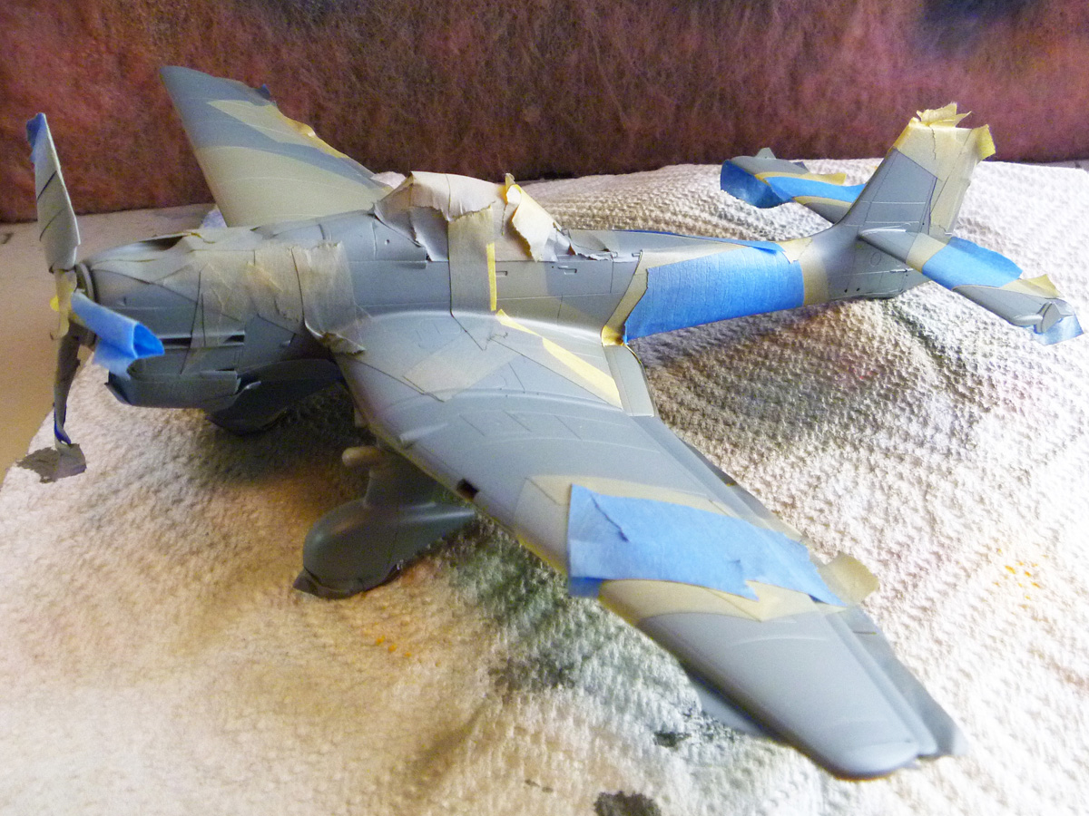
I began by painting the undersides RLM 65 (Luftwaffe blue gray), for which I owe fellow club member Scott Kruize. He made an emergency run to Emil’s for me, as my local hobby shop has sadly closed. It was during this step I ran into mistake number two: I had glued on the landing gear – which is not blue gray. Not fatal, but now I had to mask off the gear when I should have just left them off.
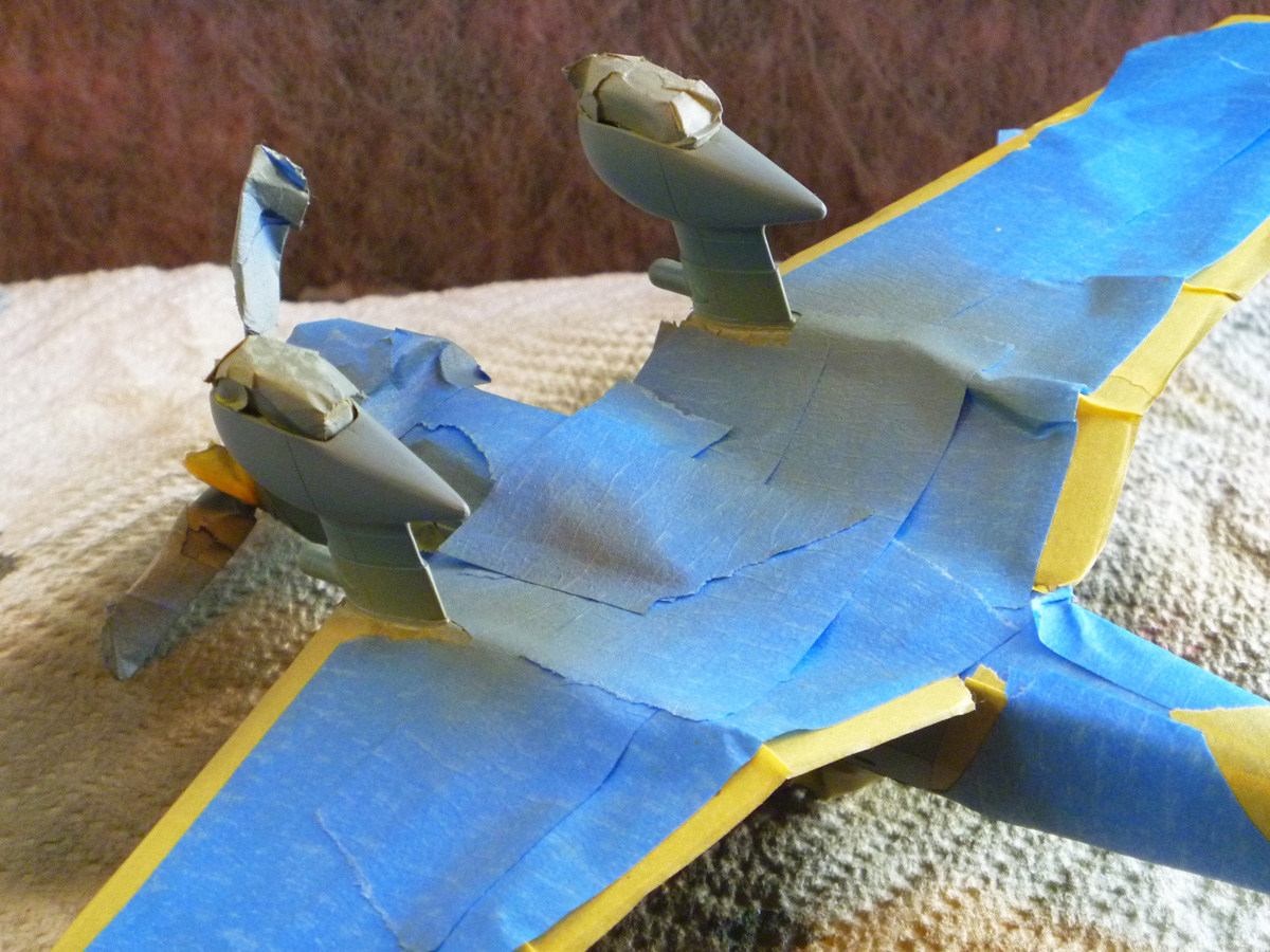 Mistake number three (a close relative of number two) was even worse, for now I had to paint the landing gear along with the upper surfaces – so now I had to mask off the entire underside!
Somehow I can’t help but think a little thoughtful planning may have come in handy…
That completed, I painted the upper surfaces a lightened RLM 71 medium green overall. Minor mistake four: I had to mask the already painted dark gray propeller - if I had let it off, no problem. That *$@’</!*+!!! prop was just in the way the whole build!
(One thing I found helpful when trying to interpret the complex camouflage scheme in the gray-on-gray instructions was to color the various areas with highlighter pens).
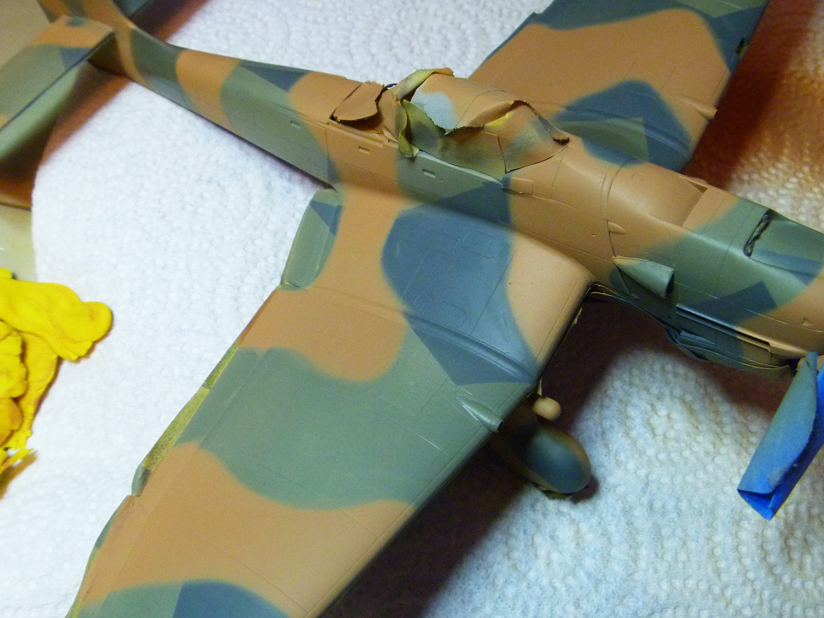
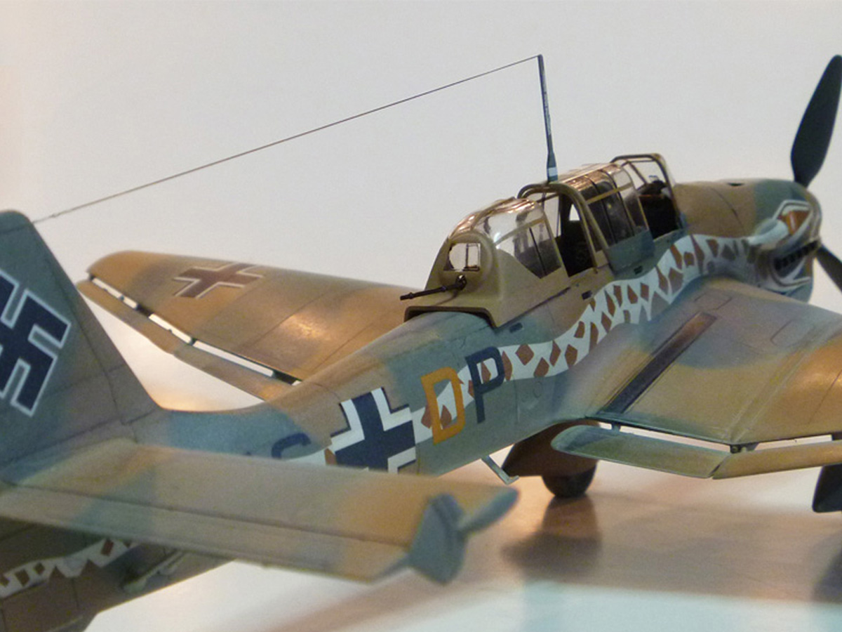
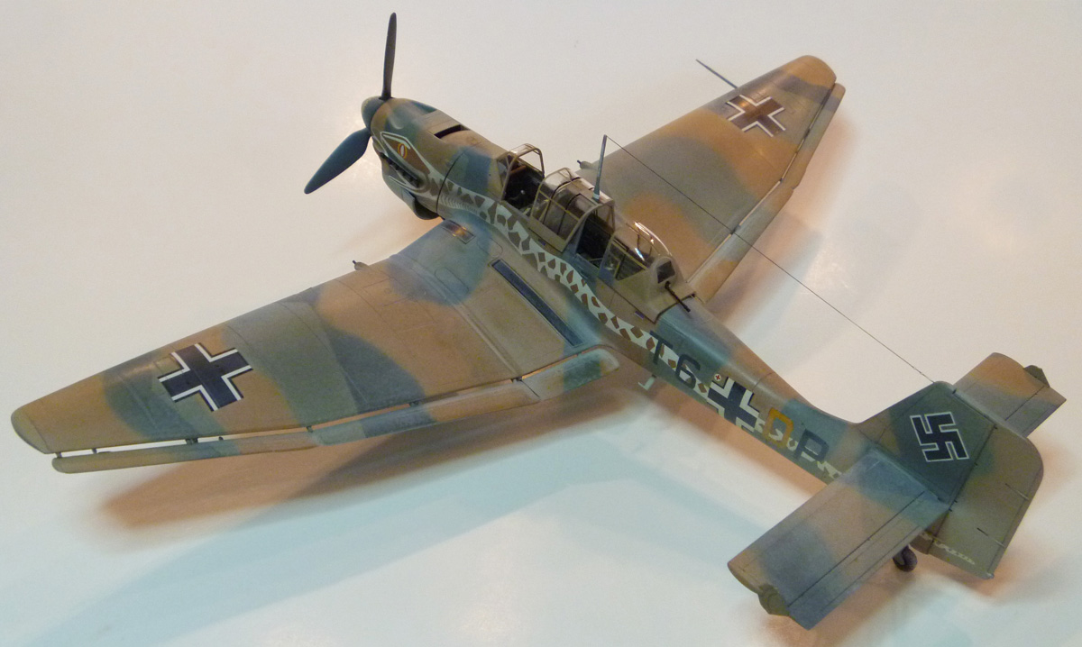
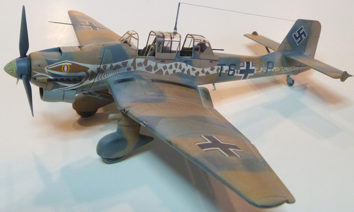
 The desert camouflage scheme of 1941 consisted of a quick overspray of sand yellow over the standard European splinter pattern. My original clever plan was to simply accomplish this with some deft free hand airbrushing, but after practicing on an old model, I realized I was not getting the consistent results I had hoped for. Time for Plan B. Out came the modeling clay. I rolled out thin ropes and laid them over the model then covered the space in between with flattened sheets of the same stuff.

Decaling
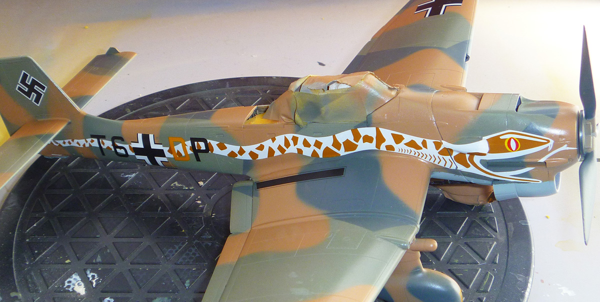
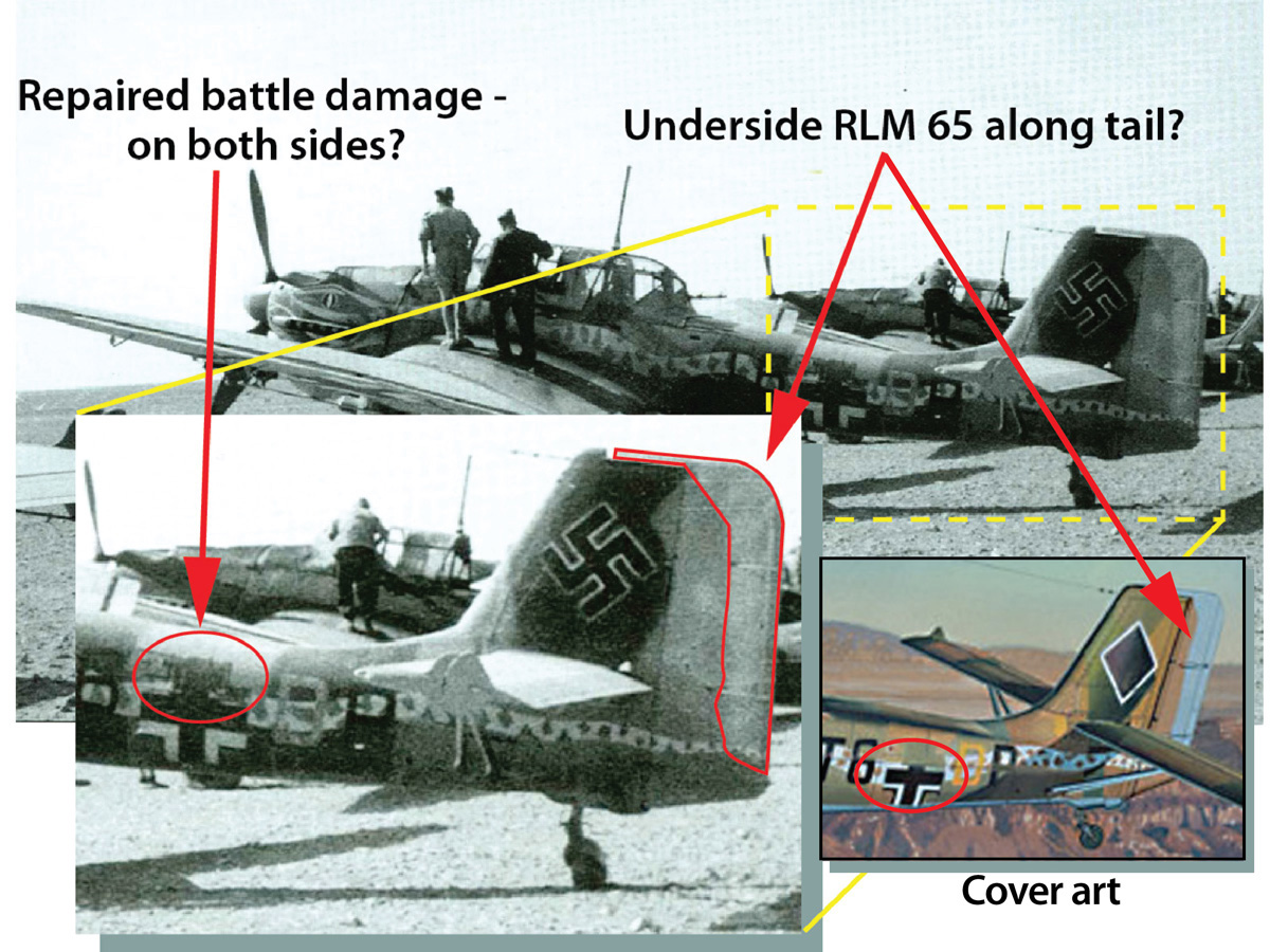
 After a coat of gloss lacquer, it’s time for the decals. They are very nice, in register and lay down very well. The only challenge was the snake. The decal is divided into three parts, one of which is just the tongue above the exhaust stubs (the left side has an extra decal to cover the carburetor air intake). The dividing line is cleverly placed to fall behind the fuselage cross. However, this means that three quarters of the snake from the head back is one long piece! Needless to say, it was another sweating bullets moment. But with a lot of solution, a soft brush and patience it went on fairly easily.
Weathering
For the weathering, I decided to really do it up. In fact, I wanted to weather it like a tank. After all, it was operating in the harshest environment imaginable and in the two pictures I found of that particular plane, it looked pretty worn. A large part of my inspiration for following the build instructions so religiously was to use the tank approach: build, build, build, paint, paint, paint (instead of the aircraft approach: build, paint, build, paint, build, paint). I attempted to use some of the techniques Eric Christensen outlines in his armor builds but I quickly realized that I didn’t have the proper materials to do it, so it was back to the drawing board. In the end I used a combination of pencils for panel lines, silver pencil for scuffing, overspray of off white and oil washes. I used very fine sandpaper to remove some of the overspray where I thought appropriate to avoid too even a coating of “dust.”
Final Steps
The last step was to attach the fiddly bits. The aileron counterbalances, tail struts, fuselage steps, etc. All of these parts have hardly anything in the way of attachment points. Each has barely a suggestion of a nub and the attachment points were little more than a slight dimple. Some scrapping, sanding and drilling help create a bondable surface and with patience and fussing all were attached. The last part was the antenna.
Conclusion
 At any rate, I think if you avoid my mistakes and try some of the more successful techniques, you’ll have a much better time and probably better results.
My thanks to Internet Modeler and Hasegawa USA for the review sample.