


Instant 3D plus!

Instant 3D! was a random idea, quickly thrown together to see if it was possible. But after seeing the cool things people can do with it, I wanted to clean it up properly, and also present some of the internal functions more cleanly.
Making the 3D functions more accessible means:
- You can often get your game working correctly in 3D even if the Instant 3D "magic" doesn't work correctly, by calling the 3D spr/map functions directly with the right parameters.
- You can do things that the original Instant 3D can't do, like having objects that hover into the air.
I've added a little tutorial of converting a 2D game to 3D to illustrate how this works, at the bottom of this post.
Obviously this "snippet" is still very limited, compared to a general purpose 3D library say. You can't use it to create an FPS or a flight simulator. But I think it's a lot easier to use - start with a 2D game, drop it in, and fix up the bits that don't come out right. And you can still do some cool looking 3D stuff with it.
Here's the updated snippet:
-- instant 3d+!

do
 -- parameters
 p3d={
  vanish={x=64,y=0}, -- vanishing pt
  d=128,             -- screen dist in pixels
  near=1,            -- near plane z
  camyoff=32,        -- added to cam y pos
  camheight=32       -- camera height
 }

 -- save 2d versions
 map2d,spr2d,sspr2d,pset2d,camera2d=map,spr,sspr,pset,camera

 -- 3d camera position
 local cam={x=0,y=0,z=0}

 -- is 3d mode enabled?
 is3d=false

 -- helper functions

 -- screen to camera space
 local function s2c(x,y,z)
  return x-cam.x,y-cam.y,z-cam.z
 end

 -- perspective projection
 local function proj(x,y,z)
  if -y>=p3d.near then
   local scale=p3d.d/-y
   return x*scale+p3d.vanish.x,-z*scale+p3d.vanish.y,scale
  end
 end

 -- screen to projected
 local function s2p(x,y,z)
  local x,y,z=s2c(x,y,z)
  return proj(x,y,z)
 end

 -- 3d drawing fns
 function sspr3d(sx,sy,sw,sh,x,y,z,w,h,fx,fy)
  w=w or sw
  h=h or sh
  local px,py,scale=s2p(x,y,z)

  if(not scale)return
  local pw,ph=w*scale,h*scale

  -- sub pixel stuff
  local x0,x1=flr(px),flr(px+pw)
  local y0,y1=flr(py),flr(py+ph)
  sspr2d(sx,sy,sw,sh,x0,y0,x1-x0,y1-y0,fx,fy)
 end

 spr3d=function(n,x,y,z,w,h,fx,fy)
  if(not z)return
  -- convert to equivalent sspr() call
  w=(w or 1)*8
  h=(h or 1)*8
  local sx,sy=flr(n%16)*8,flr(n/16)*8
  sspr3d(sx,sy,w,h,x,y,z,w,h,fx,fy)
 end

 function map3d(cx,cy,x,y,z,w,h,lyr)
  if(not h)return

  -- near/far corners
  local fx,fy,fz=s2c(x,y,z)
  local nx,ny,nz=s2c(x,y+h*8,z)

  -- clip
  ny=min(ny,-p3d.near)
  if(fy>=ny)return

  -- project
  local npx,npy,nscale=proj(nx,ny,nz)
  local fpx,fpy,fscale=proj(fx,fy,fz)

  if npy<fpy then
   local tx,ty,ts=npx,npy,nscale
   npx,npy,nscale=fpx,fpy,fscale
   fpx,fpy,fscale=tx,ty,ts
  end

  -- clamp
  npy=min(npy,128)
  fpy=max(fpy,0)

  -- rasterise
  local py=flr(npy)
  while py>=fpy do

   -- floor plane intercept
   local g=(py-p3d.vanish.y)/p3d.d
   local d=-nz/g

   -- map coords
   local mx,my=cx,(-fy-d)/8+cy

   -- project to get left/right
   local lpx,lpy,lscale=proj(nx,-d,nz)
   local rpx,rpy,rscale=proj(nx+w*8,-d,nz)

   -- delta x
   local dx=w/(rpx-lpx)

   -- sub-pixel correction
   local l,r=flr(lpx+0.5)+1,flr(rpx+0.5)
   mx+=(l-lpx)*dx

   -- render
   tline(l,py,r,py,mx,my,dx,0,lyr)

   py-=1
  end
 end

 function map3dupright(cx,cy,x,y,z,w,h,lyr)
  if(not h)return
  local px,py,scale=s2p(x,y,z)
  if(not scale)return

  local pw,ph=w*8*scale,h*8*scale

  -- texture step
  local dx,dy=w/pw,h/ph
  local mx,my=cx+0.0625,cy+0.0625

  -- sub pixel stuff
  local x0,x1=flr(px),flr(px+pw)
  local y0,y1=flr(py),flr(py+ph)
  mx+=(x0-px)*dx
  my+=(y0-py)*dy

  if(x0>=x1 or y0>=y1)return

  for y=y0,y1-1 do
   tline(x0,y,x1,y,mx,my,dx,0,lyr)
   my+=dy
  end
 end

 function camera3d(x,y,z)
  cam.x,cam.y,cam.z=x,y,z
 end

 -- "instant 3d" wrapper functions
 local function icamera(x,y)
  cam.x=(x or 0)+64
  cam.y=(y or 0)+128+p3d.camyoff
  cam.z=p3d.camheight
 end

 local function isspr(sx,sy,sw,sh,x,y,w,h,fx,fy)
  z=h or sh
  y+=z
  sspr3d(sx,sy,sw,sh,x,y,z,w,h,fx,fy)
 end

 local function ispr(n,x,y,w,h,fx,fy)
  z=(h or 1)*8
  y+=z
  spr3d(n,x,y,z,w,h,fx,fy)
 end

 local function imap(cx,cy,x,y,w,h,lyr)
  cx=cx or 0
  cy=cy or 0
  x=x or 0
  y=y or 0
  w=w or 128
  h=h or 64
  map3d(cx,cy,x,y,0,w,h,lyr)
 end

 function go3d()
  camera,sspr,spr,map=icamera,isspr,ispr,imap
  camera2d()
  is3d=true
 end

 function go2d()
  map,spr,sspr,pset,camera=map2d,spr2d,sspr2d,pset2d,camera2d
  is3d=false
 end

 -- defaults
 icamera()
end

-- enable 3d mode
go3d()
menuitem(3,"3d",go3d)
menuitem(2,"2d",go2d) |
As before, to use it, just copy it into your 2D program. It should behave exactly the same.
There's one new feature, in that you can toggle between 2D and 3D in the Pico-8 menu.

You can also do it in code using
go2d() |
and
go3d() |
which might be useful for 2D title screens etc.
Taking it further
The basics are the same as before, but you can now - with a little bit of work - take your games a bit further by making use of explicit 2D and 3D commands, rather than leaving it up to the snippet to guess your intent.
To illustrate this, I made a little 2D cart to convert into 3D.


This is a simple little game where you're a bouncing ball that collects coins. It's not finished, but is enough to demonstrate the process. The game is already a little bit 3D in that the ball and coins also have a height, and objects can move in front and behind each other, so it has to sort their positions and draw them from back to front.

Dropping the snippet into this program has... mixed results.

As you can see, it's kind of 3D, but it has some issues:
- The ball doesn't always bounce straight up. In fact if you look closely it's actually staying on the ground and just bounces away and back again.
- The coins aren't raised up properly either.
- The metallic struts are flat on the ground, rather than standing up.
- Likewise the gratings on top are also flat on the ground.
- The 3 lives are displayed in the wrong place.
Obviously the snippet doesn't know exactly what we're trying to achieve, but fortunately we can help it out.
With a little bit of work we can make it look like this:
3D functions
We can fix up the ball using an explicit 3D function. The snippet provides explicit 3D functions spr3d, sspr3d and map3d. They have the same parameters as the standard functions, except there's a Z parameter immediately after the X and Y screen parameters.
They use a 3D coordinate system where:
- The X axis is to the right
- The Y axis is out of the screen (towards you)
- The Z axis is up
This keeps X and Y consistent with the "Instant 3D" logic, where instead of moving up the screen as Y decreases, objects move away from you. The new Z parameter allows us to also specify the height.
The ball drawing code looks like this:
  elseif thing.typ=="player" then
   shadowcols()
   sspr(0,32,
      8,8,
     thing.x-4,thing.y-1,
     8,4)
   pal()
   spr(64+thing.frame%9,
       thing.x-4,
       thing.y-thing.height-8)
end |
The sspr() call draws the shadow, which looks correct already, so it doesn't need to change.
The spr() call draws the ball, based on the thing.x,-.y and -.height variables. The game stores the position of bottom center of the ball, so it has to subtract 4 and 8 to get the top left corner for spr().
We can change it to an explicit 3D call as follows:
   spr3d(64+thing.frame%9,
       thing.x-4,
       thing.y,
thing.height+8) |
We're still specifying the top left corner, but now it's in 3D.
The coin code is similar:
  if thing.typ=="coin" then
   shadowcols()
   sspr(0,40,
        8,8,
        thing.x-4,thing.y-1,
        8,4)
   pal()
   spr(80,
thing.x-4,thing.y-thing.height-8) |
Once again we change the spr call to an spr3d:
   spr3d(80,
       thing.x-4,
       thing.y,
thing.height+8) |
With 3D positions supplied, the ball and coins now bounce/float above the ground properly.

Upright maps
Next we can address the red metal structs. Currently they are lying flat on the ground instead of standing up straight.
The "instant 3D" snippet assumes everything drawn with "spr"/"sspr" is upright, and everything drawn with "map" is flat on the ground. However the struts are drawn using map(), so that they can be composed of multiple sprites.
So we need to tell the game to draw them upright.
map3d won't help in this case. We can use it to draw them higher up, but they will still be lying flat, not standing upright. So to help with this the snippet provides an alternative "map3dupright" function.
The strut drawing code is:
  elseif thing.typ=="strut" then
   map(127,0,
       thing.x,thing.y-40,
1,5) |
We can change the map call to a map3dupright like this:
   map3dupright(127,0,
       thing.x,
       thing.y,
       40,
1,5) |
Once again it has the same parameters as "map", except there's a Z parameter immediately after the X and Y.
The struts are 40 pixels high, so we set the Z (i.e. the height) to 40, to specify the top left corner position.
With this in place, the struts now stand upright.


3D parameters
Now that objects are above the ground they often disappear above the top of the screen.
This is due to the camera height, and the "vanishing point" of the 3D projection, which is currently set to the top of the screen.
We can easily fix this by changing the 3D parameters.
The default parameters are in the snippet:
 -- parameters
 p3d={
  vanish={x=64,y=0}, -- vanishing pt
  d=128,             -- screen dist in pixels
  near=1,            -- near plane z
  camyoff=32,        -- added to cam y pos
  camheight=32       -- camera height
} |
We can move the vanishing point into the center of the screen by adding a line to the _init function:
p3d.vanish.y=64 |
Moving the vanishing point is like rotating the camera upwards slightly. Now we can easily see everything.
In fact we can even move the camera down a little and nearer to the ball:
p3d.camheight=20 p3d.camyoff=20 |

3D map coordinates
Now we'll fix the metal grates. These are supposed to sit on top of the struts.
The grates are rendered as a single map, much like the floor. We need to tell the game to draw that map above the ground.
This time map3d is the correct function to use.
The existing code looks like this.
-- roof map map(32,0,0,-40,16,64) |
The 3D code is quite similar:
-- roof map map3d(32,0,0,0,40,16,64) |
Once again we have a new Z parameter after the X and Y, which we set to 40 to move it up into the air.
In the 2D version the grates are drawn last, as because they are above everything. However in the 3D version they actually need to be drawn before the ball, coins and struts to get the correct ordering.
So the line should be moved up immediately after the "map" call that draws the floor.
2D drawing
The last thing to fix is the lives display. Lives are displayed as 3 balls, but they are drawn in the wrong place, because the "instant 3D" logic is trying to position them in 3D.
In this case we really just want to draw them in 2D.
Fortunately the snippet saves the original 2D functions as "spr2d", "sspr2d" and "map2d", so we can call them directly if we need to.
The life drawing code looks like this:
-- overlay
camera()
fancyprint("lives",4,4,12)
for i=1,player.lives do
 spr(64,25+(i-1)*9,2)
end |
Simply change the "spr" to "spr2d" and we're done.
2D/3D code
Adding the various 3D calls makes the game look correct in 3D now. But if you switch it back to 2D (via the pause menu) it now looks broken.
One solution is to simply remove the "menuitem" calls from the snippet and disable mode switching. This is perfectly valid if the game is only supposed to be 3D.
But if you really do want the 2D option, it is still possible. The snippet includes a variable "is3d" which is set to true in 3D mode. Before calling any 3D function, check it to ensure you are actually in 3D mode. If not, perform the original 2D call instead. For example:
if is3d then spr3d(64+thing.frame%9, thing.x-4, thing.y, thing.height+8) else spr(64+thing.frame%9, thing.x-4, thing.y-thing.height-8) end |
Here's the final cart with 2D and 3D mode support.

Other bits
That's the gist of how to use it. There are a couple of functions I've missed, like camera3d (sets the 3D camera position explicitly, rather than inferring it from the 2D position and height/y-offset parameters), and a pset3d/pset2d which should do what you'd expect.
Feel free to throw me any questions you have.
-Mot
** Update 1: Fix spr() when drawing larger than 1x1 sprites
 44 comments
I often find myself declaring a lot of arrays/object literals that are essentially just data. No computation involved.
For example:
-- background types
bg_tree={
 tex={
  {sx=0,sy=64,sw=32,sh=32}
 },
 w=2,h=2,
 spacing=2
}
bg_lamp={
 tex={
  {sx=0,sy=32,sw=16,sh=8}
 },
 w=.5,h=.25,
 spacing=2,
 trans=12
}
|
It's a useful way to create flexible, extendable systems.
Unfortunately it quickly chews through the token count.
So I was wondering what people's views were of changing the token counting rules around such object literals? - say 1 token per object literal.
They would have to be restricted in order to qualify for a reduced token count, i.e. data only, no computation, functions etc, similar to how JSON is a restricted subset of JavaScript.
The compiler could either detect this automatically, or possibly a new "data only literal" syntax could be introduced.
I feel like this probably aligns with the PICO-8 principals, as it's arguably data rather than code, and you still have the compressed size limit. It seems like a much cleaner solution than the string shredding/JSON parsing workarounds that are currently used.
Variable inspector window

Debugging carts with "print" and "printh" can be cumbersome, so I made a little snippet to help.
It adds a little window where you can view variables and drill down into them.
To use it, add the snippet somewhere into your program:
dbg=(function()

    poke(0x5f2d, 1)

    -- watched variables
    local vars,emp={},true

    -- window state
    local exp=false

    -- text cursor
    local x,y

    -- scrollbar
    local sy=0
    local sdrag

    -- mouse state
    local mx,my,mb,pb,click,mw

    function clicked(x,y,w,h)
        return click and mx>=x and mx<x+w and my>=y and my<y+h
    end

    function butn(txt,x,y,c)
        print(txt,x,y,c)
        return clicked(x,y,4,6)
    end

    -- convert value into something easier to traverse and inspect
    function inspect(v,d)
        d=d or 0
        local t=type(v)
        if t=="table" then
            if(d>5)return "[table]"
            local props={}
            for key,val in pairs(v) do
                props[key]=inspect(val,d+1)
            end
            return {
                expand=false,
                props=props
            }
        elseif t=="string" then
            return chr(34)..v..chr(34)
        elseif t=="boolean" then
            return v and "true" or "false"
        elseif t=="nil" or t=="function" or t=="thread" then
            return "["..t.."]"
        else
            return ""..v
        end
    end

    function drawvar(var,name)
        if type(var)=="string" then
            print(name..":",x+4,y,6)
            print(var,x+#(""..name)*4+8,y,7)
            y+=6
        else

            -- expand button
            if(butn(var.expand and "-" or "+",x,y,7))var.expand=not var.expand

            -- name
            print(name,x+4,y,12) y+=6

            -- content
            if var.expand then
                x+=4
                for key,val in pairs(var.props) do
                    drawvar(val,key)
                end
                x-=4
            end
        end
    end

    function copyuistate(src,dst)
        if type(src)=="table" and type(dst)=="table" then
            dst.expand=src.expand
            for key,val in pairs(src.props) do
                copyuistate(val,dst.props[key])
            end
        end
    end

    function watch(var,name)
        name=name or "[var]"
        local p,i=vars[name],inspect(var)
        if(p)copyuistate(p,i)
        vars[name]=i
        emp=false
    end

    function clear()
        vars,emp={},true
    end

    function draw(dx,dy,w,h)
        dx=dx or 0
        dy=dy or 48
        w=w or 128-dx
        h=h or 128-dy

        -- collapsed mode
        if not exp then
            dx+=w-10
            w,h=10,5
        end

        -- window
        clip(dx,dy,w,h)
        rectfill(0,0,128,128,1)
        x=dx+2 y=dy+2-sy

        -- read mouse
        mx,my,mw=stat(32),stat(33),stat(36)
        mb=band(stat(34),1)~=0
        click=mb and not pb and mx>=dx and mx<dx+w and my>=dy and my<dy+h
        pb=mb

        if exp then

            -- variables
            for k,v in pairs(vars) do
                drawvar(v,k)
            end

            -- scrollbar
            local sh=y+sy-dy
            if sh>h then
                local sx=dx+w-4
                local by=sy/sh*h+dy
                local bh=h/sh*h
                rectfill(sx,dy,dx+w,dy+h-1,5)
                rectfill(sx,by,dx+w,by+bh-1,sdrag and 12 or 6)
                rect(sx,by,dx+w-1,by+bh-1,13)
                if click and mx>=sx then
                    if my<by then
                        sy-=h
                    elseif my>by+bh then
                        sy+=h
                    else
                        sdrag=by-my
                    end
                end
                if sdrag then
                    sy=(my+sdrag-dy)*sh/h
                else
                    sy-=mw*8
                end
                if(sy<0)sy=0
                if(sy+h>sh)sy=sh-h
                if(not mb)sdrag=nil
            else
                sy=0
            end

            -- clear btn
            if(butn("x",dx+w-15,dy,14))clear()
        end

        -- expand/collapse btn
        if(butn(exp and "-" or "+",dx+w-10,dy,14))exp=not exp

        -- draw mouse ptr
        clip()
        line(mx,my,mx,my+2,8)
        color(7)
    end

    function show()
        exp=true
        while exp do
            draw()
            flip()
        end
    end

    function prnt(v,name)
        watch(v,name)
        show()
    end

    return{
        watch=watch,
        clear=clear,
        empty=function()
            return emp
        end,
        expand=function(val)
            if(val~=nil)exp=val
            return exp
        end,
        draw=draw,
        show=show,
        print=prnt
    }
end)() |
There are a few different ways to use it.
Global variables
You can view global variables when your program is paused by typing:
dbg.print(myvariable) |

The window will popup and run until you click "-" at the top right to exit it.
Note: If you press "Esc" to exit the inspection window, and try to resume your game with "resume", it will resume the popup window instead! To avoid this, use the "-" button.
Local variables
To view a local variable inside a function you need to add code to that function to capture it.
dbg.watch(myvariable,"my variable") |
This will capture it's value and add it to your variable list. The second parameter is the name. You can add multiple variables so long as they all have different names. Calling dbg.watch again with the same name causes it to replace the previous value.
To view your captured variables, pause your program by pressing Esc, and type:
dbg.show() |

Be aware that the variable inspector window shows the variable's value at the time dbg.watch() was executed. If the variable has been changed since, the changes will not show in the inspector. (This is deliberate.)
Displaying variables while the program is running
If you want to run the inspector window directly in your program, add:
dbg.draw() |
to your _draw() function.
You can optionally specify the window position (x,y,width,height), e.g.
dbg.draw(64,0,64,48) |
By default the window displays collapsed, until you click the "+" button.

Remember you still need to capture variables with "dbg.watch()", otherwise the window will be empty.
Pausing while the inspector is open
The game will continue running while the inspector window is open.
If you'd prefer it to pause the game, you can add:
if(dbg.expand())return |
to the top of your "_update" function.
dbg.expand() |
returns true when the window is expanded or false when collapsed.
You can also force it open with:
dbg.expand(true) |
or collapse it with:
dbg.expand(false) |
For example, to invoke the editor from the Pico-8 built in menu:
menuitem(1,"debug",function()dbg.expand(true)end) |
Performance considerations
This snippet works by traversing your variables and building a "snapshot" tree structure. If you capture large variables every frame you might get some slow down, due to the traversal and possibly the Lua garbage collector cleaning up snapshots from previous frames. So make sure to remove your dbg.watch() calls when you want your program to run fast again.
|
74 
|
Turn your 2D game into a 3D game!


That's 50% extra D!
100% guaranteed to work, sometimes, if you're lucky.
Simply paste this into the top of your 2D game, and be the envy of all your 2D coding friends!!!1!1
(OK, I'll stop now.)
This works best for top down games like "Pic-oh mummy!" by @Hokutoy, "Pakutto boy" by @Konimiru (both pictured)
Admittedly it's more of a gimmick/experiment - the result isn't very playable due to not being able to see the whole play area.
I mainly just wanted to see if it would work :)
_={
 map=map,
 spr=spr,
 sspr=sspr,
 pset=pset,
 circ=circ,
 camera=camera,
 cx=0,
 cy=0,
 cyoff=32,
 ch=32,
 d=128,
 ymid=0,
 s2w=function(x,y)
  return (x-_.cx)-64,_.ch,128-(y-_.cy)
 end,
 proj=function(x,y,z)
  local scale=_.d/z
  return x*scale+64,y*scale+_.ymid,scale
 end
}

camera=function(x,y)
 _.cx=x or 0
 _.cy=(y or 0)+_.cyoff
end

camera(0,0)

pset=function(x,y,c)
 local wx,wy,wz=_.s2w(x,y)
 if(wz<1)return
 local px,py=_.proj(wx,wy,wz)
 _.pset(px,py,c)
end

circ=function(x,y,r,c)
 local wx,wy,wz=_.s2w(x,y)
 if(wz<1)return
 local px,py,scale=_.proj(wx,wy,wz)
 _.circ(px,py,r*scale,c)
end

sspr=function(sx,sy,sw,sh,x,y,w,h,fx,fy)
 w=w or sw
 h=h or sh
 local wx,wy,wz=_.s2w(x+w/2,y+h)
 if(wz<1)return
 local px,py,scale=_.proj(wx,wy,wz)
 local pw,ph=w*scale,h*scale

 -- sub pixel stuff
 local x0,x1=flr(px-pw/2),flr(px+pw/2)
 local y0,y1=flr(py-ph),flr(py)

 _.sspr(sx,sy,w,h,x0,y0,x1-x0,y1-y0,fx,fy)
end

spr=function(n,x,y,w,h,fx,fy)
 if(not n or not x or not y)return
 -- convert to equivalent sspr() call
 w=(w or 1)*8
 h=(h or 1)*8
 local sx,sy=flr(n%16)*8,flr(n/16)*8
 sspr(sx,sy,w,h,x,y,w,h,fx,fy)
end

map=function(cx,cy,x,y,w,h,lyr)
 cx=cx or 0
 cy=cy or 0
 x=x or 0
 y=y or 0
 w=w or 128
 h=h or 64

 -- near/far corners
    local fx,fy,fz=_.s2w(x,y)
    local nx,ny,nz=_.s2w(x,y+h*8)

 -- clip
 nz=max(nz,0.5)
 if(fz<=nz)return

 -- project
 local npx,npy,nscale=_.proj(nx,ny,nz)
 local fpx,fpy,fscale=_.proj(fx,fy,fz)

 -- clamp
 npy=min(npy,128)

 -- rasterise
 local py=flr(npy)
 while py>=fpy do

  -- floor plane intercept
        local g=(py-_.ymid)/_.d
        local z=_.ch/g

        -- map coords
        local mx,my=cx,(fz-z)/8+cy

        -- project to get left/right
        local lpx,lpy,lscale=_.proj(nx,ny,z)
        local rpx,rpy,rscale=_.proj(nx+w*8,ny,z)

        -- delta x
        local dx=w/(rpx-lpx)

        -- sub-pixel correction
        local l,r=flr(lpx+0.5)+1,flr(rpx+0.5)
        mx+=(l-lpx)*dx

  -- render
        tline(l,py,r,py,mx,my,dx,0,lyr)

  py-=1
 end
end |
EDIT 1: adjusted near plane to avoid numeric overflow. Defaults for omitted map() parameters.
EDIT 2: also 3Dise sspr, pset and circ
EDIT 3: sub-pixel logic
EDIT 4: add map() layer parameter. fix gaps between adjacent sprites.
New version!
I've made a new version called Instant 3D plus! :-).
It should behave exactly like the original, but it's cleaned up quite a bit, and you can call the 3D functions directly to fix the bits that it doesn't get right automatically - or place things in exact 3D positions (like up in the air).
More details in the other post.
!!!!!!!!!!!!!!!!!!!!!!!!!!!!!!!!!!!!!!!!!!!!!!!!!!!!!!!!!!!!!!!!!!!!!!!!!!!!!!!!!!!!!!!!!!!!!!!!!!!!!!!!!!!!!!!!!!!!!!!!!!
This is an older work-in-progress version! Play the completed released version here.
!!!!!!!!!!!!!!!!!!!!!!!!!!!!!!!!!!!!!!!!!!!!!!!!!!!!!!!!!!!!!!!!!!!!!!!!!!!!!!!!!!!!!!!!!!!!!!!!!!!!!!!!!!!!!!!!!!!!!!!!!!

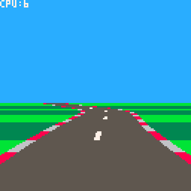
This is a little scaled-sprite 3D graphics engine inspired by the old classic game Power Drift.
Still work in progress. Needs some basic game-play rules (laps, win/lose etc) and some difficulty balancing. But it's playable.


Update
- Fixed bug in saving tracks to external cart.
- Added a little bit of steering assist to help line up the jumps.
- Some other tweaks I forget :)
Update 2
- 2 tracks
- Track selector
- Trees generate in the same place
Update 3
- New track
- (Slightly) better physics/collisions
- Finish line and corner signs
Update 4
- New larger test track
- Performance optimisations. LOD system. More aggressive view volume culling
- Tweaked the steering
Update 5
- More performance tweaks
Update 6
- More performance tweaks, thanks to @freds72
- Updated physics to support driving upside down!
- New track with loop-the-loop (to test driving upside down :)
Update 7
- AI cars. WIP. No collisions yet. Difficulty will probably be scaled down a bit eventually.
- Moved editor to separate cart.
- I tried to draw a palm tree.
Update 8
- Different AI car colours.
- Fixed flip-Y logic when AI cars are upside down.
*Update 9
- Basic car collisions
- AI cars now steer around each other (and you)
Update 10
- Cockpit graphics with animated front wheels.
- Main menu
- Race start sequence
Update 11
- Fix wheel animation when frame rate <30
- Fix NPC cars getting stuck on hills
Update 12
- Lap and position displayed on screen
- Race finishes after 5 laps
- Note: Difficulty level logic is not hooked up yet!
Update 13
- Hook up difficulty levels
- First attempt at engine sounds
- "Ramps" logo :)

A little <560 chars game.
Press left/right to dodge between the white balls.
Vaguely inspired by "Beam rider", so there's actually 5 lanes to jump between. I ran out of chars before I could draw the lanes though :)

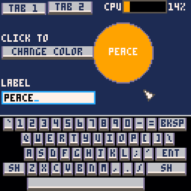
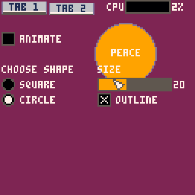
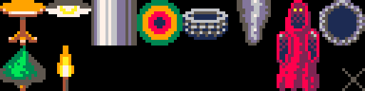
For some reason I felt like writing a little immediate-mode GUI library.
It has:
- Labels
- Buttons
- Check boxes
- Radio buttons
- Sliders
- Text boxes
You write into the text boxes on a little popup keyboard.
It works best with the mouse, but it can run in controller-only mode, where you move the pointer around with the direction arrows (it's pretty cumbersome though).
"Immediate mode" means you call the functions to draw the widgets in your drawing code, and it returns the user's input. It's generally easier to integrate into projects than a traditional widget UI would be, as you don't have to create and manage objects, you just draw the UI controls you need where and when you need them.
The first tab in the source is the library. The second is a little demo, that doubles as the documentation :)
UPDATE: Better looking buttons (thanks @freds72)

This tutorial is part 3 of a series. View part 1 here.
And the end of part 2 we had roadside objects drawn using scaled sprites and sections of the map.
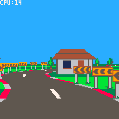
Everything so far has been flat, so in this tutorial we will add some hills and valleys.
This will require solving some overlap issues which we will solve using a clip rectangle "trick", which will in turn set us up nicely for implementing tunnels - so we'll do that too.
Defining the pitch
First we'll define the pitch of each corner with a field called "pi" (not to be mistaken for the Greek letter and mathematical constant).
road={
 {ct=10,tu=0,bgl=bg_tree,bgr=bg_tree},
 {ct=6,tu=-.25,bgl=bg_tree,bgr=bg_sign},
 {ct=8,tu=0,pi=-.75,bgl=bg_tree,bgr=bg_tree},
 {ct=4,tu=.375,bgl=bg_sign,bgr=bg_tree},
 {ct=10,tu=0.05,pi=.75,bgl=bg_tree},
 {ct=4,tu=0,bgl=bg_tree,bgr=bg_tree},
 {ct=5,tu=-.25,bgl=bg_tree,bgr=bg_sign},
 {ct=15,tu=0,pi=-.5,bgc=bg_beams},
 {ct=12,tu=0,bgl=bg_house,bgr=bg_house},
 {ct=8,tu=-.5,bgl=bg_house,bgr=bg_sign},
 {ct=8,tu=.5,bgl=bg_sign,bgr=bg_house},
} |
This will define the gradient at the start of each corner. So a "pitch" of 1 means the ground rises 1 unit for every unit it advances forward - a 45 degree incline. Likewise -1 would be a 45 degree decline. And 0 is of course level.
For brevity we've made the pitch optional - it will default to 0 if not supplied.
To make the hills and valleys smooth the pitch will smoothly interpolate between values across each corner. We will calculate the delta to add to the pitch for each segment in the _init() method:
-- calculate the change in pitch -- per segment for each corner. for i=1,#road do local corner=road[i] local pi=corner.pi or 0 local nextpi=road[i%#road+1].pi or 0 corner.dpi=(nextpi-pi)/corner.ct corner.pi=pi end |
The pitch delta is stored in field "dpi" (not to be confused with "dots per inch" - naming stuff is hard).
Drawing
The pitch affects the vertical direction of the road as it is drawn. We actually already have a "yd" variable which is added to the y coordinate after each segment is drawn. It's just that until now the yd has always been 0, so the ground has always been flat. Now we can use it to create the hills and valleys.
First we calculate the initial value at the start of _draw()
-- direction local camang=camz*road[camcnr].tu local xd=-camang local yd=road[camcnr].pi+road[camcnr].dpi*(camseg-1) local zd=1 |
This is the start value "pi" plus the delta "dpi" added for every segment the camera has traversed along the corner.
Then we add "dpi" to the "yd" after each segment is drawn, similar to how we've added the turn "tu" to "xd":
-- turn and pitch xd+=road[cnr].tu yd+=road[cnr].dpi |
This is all we need to give the road a smooth rising and falling effect.

A note on camera movement
It's worth pointing out that the camera automatically follows the shape of the hills and valleys smoothly, without us having to write any specific code.
This works, because the camera position is skewed in the direction of the segment it is on. Back in tutorial one we implemented the skew function like this:
function skew(x,y,z,xd,yd) return x+z*xd,y+z*yd,z end |
In particular the "y+z*yd" ensures the camera moves up and down with the shape of the road.
Storing positions "unskewed" and skewing them at draw time has some advantages. Regardless of how the road turns or pitches:
- The ground is always at y=0
- The center of the road is always at x=0
- The sides of the road are always at x=+/-3
This approach will also make implementing AI cars easier later on.
Clipping
The hills and valleys introduce some obvious overlap issues - sprites visible through hills, far away ground being drawn in front instead of behind.
One approach to fixing this would be to change the road drawing order so that it is back-to-front as well.
This would be a perfectly valid approach (although it would require careful management to incorporate the sprites and road/ground at the same time).
However we're going to use a different approach. We're going to use clipping rectangles to prevent far away road/ground being drawn over near objects.
It will work like this:
- We start with a clipping rectangle covering the whole screen. I.e. nothing is clipped.
- As we draw forward, we move the bottom of the clipping rectangle up so that it does not include the road and ground we have just drawn.
- The clipping rectangle prevents anything drawn further down the road from overlapping with what we've already drawn. Anything that would overlap will simply be clipped away.
The advantage of this method is that we can continue drawing the road as we walk forward along it. We don't have to change the algorithm too much.
It also reduces overdraw, which was important back-in-the-day on platforms that were fill-rate limited. Pico-8 drawing is fast enough that it doesn't really matter though.
To start with we define the initial clip region before the main drawing loop:
 -- current clip region
 local clp={0,0,128,128}
clip() |
The "clp" array defines the left, top, right and bottom values in that order.
We reduce the clip region after drawing each segment, immediately after adding the background sprites (for reasons we'll see later):
-- reduce clip region clp[4]=min(clp[4],ceil(py)) setclip(clp) |
The "min" function ensures that the bottom of the rectangle only ever moves up, which is important for drawing crests of hills correctly.
"setclip" is simply a helper function that sets the Pico-8 clip region for drawing:
function setclip(clp) clip(clp[1],clp[2],clp[3]-clp[1],clp[4]-clp[2]) end |
Putting this together we get:

Clipping sprites
The hills are no longer see through, but now the background sprites are not being drawn correctly. The problem is the sprites are being drawn after the road, when the clipping rectangle has been reduced to cover just the sky. We could reset the clipping rectangle to cover the whole screen before drawing the sprites, which would improve things, but sprites would still be visible through the hills.
What we really need to do is draw each sprite using the clipping rectangle that was active when its segment was drawn, which we can do by storing a copy of the clip rectangle in the sprites array.
We'll add a "clp" parameter to addbgsprite:
function addbgsprite(sp,sumct,bg,side,px,py,scale,clp)

 ...

 -- add to sprite array
 add(sp,{
  x=px,y=py,w=w,h=h,
  img=bg.img,
  mp=bg.mp,
  flp=flp,
  clp={clp[1],clp[2],clp[3],clp[4]}
 })
end |
It's important that we create a new array and copy each of the "clp" fields individually, so that we get a snapshot of the "clp" array at that point. Referencing "clp" directly would not work, because "clp" changes as the road is drawn.
Now we update the calls in the main drawing loop to pass in the clipping rectangle:
-- add background sprites addbgsprite(sp,sumct,road[cnr].bgl,-1,px,py,scale,clp) addbgsprite(sp,sumct,road[cnr].bgr, 1,px,py,scale,clp) addbgsprite(sp,sumct,road[cnr].bgc, 0,px,py,scale,clp) |
Finally we apply the clipping rectangle in drawbgsprite:
function drawbgsprite(s) setclip(s.clp) ... |
With this in place we should have hills and valleys drawn correctly, including the background sprites.

Tunnels
For the last part of this tutorial we will implement basic tunnels. Tunnels give racing games a cool change of environment and they're just fun to drive through.
And with the clipping rectangle logic is in place they're reasonably straightforward to implement.
It's essentially an extension of the clipping logic used for the ground. But now we also reduce the top of the clipping rectangle as we draw the tunnel ceiling, and the left and right sides as we draw the tunnel walls.
We'll start by defining the tunnel in our road:
road={
 {ct=10,tu=0,bgl=bg_tree,bgr=bg_tree},
 {ct=6,tu=-.25,bgl=bg_tree,bgr=bg_sign},
 {ct=8,tu=0,pi=-.75,bgl=bg_tree,bgr=bg_tree},

 {ct=8,tu=0,tnl=true},
 {ct=4,tu=0,tnl=true},
 {ct=8,tu=0,pi=.75,tnl=true},
 {ct=8,tu=-.5,pi=.75,tnl=true},
 {ct=4,tu=0,tnl=true},
 {ct=8,tu=.5,tnl=true},
 {ct=4,tu=0,pi=-.5,tnl=true},
 {ct=8,tu=0,pi=-.5,tnl=true},

 {ct=4,tu=.375,bgl=bg_sign,bgr=bg_tree},
 {ct=10,tu=0.05,pi=.75,bgl=bg_tree},
 {ct=4,tu=0,bgl=bg_tree,bgr=bg_tree},
 {ct=5,tu=-.25,bgl=bg_tree,bgr=bg_sign},
 {ct=15,tu=0,pi=-.5,bgc=bg_beams},
 {ct=12,tu=0,bgl=bg_house,bgr=bg_house},
 {ct=8,tu=-.5,bgl=bg_house,bgr=bg_sign},
 {ct=8,tu=.5,bgl=bg_sign,bgr=bg_house},
} |
Tunnel corners are denoted by "tnl=true".
I've placed the tunnel section towards the start of the road so that it's quicker to get to for testing and debugging. (It can be moved later once everything is working correctly).
Tunnel front face
Next we'll draw the tunnel face.
We need to detect the first corner tunnel ("tnl" is set to true) where the previous corner was not a tunnel, which we can do by tracking the tunnel flag for the current corner, and the previous corner.
We set the initial value of the previous tunnel flag before the main drawing loop:
-- previous tunnel flag local ptnl=road[cnr].tnl |
Strictly speaking this should be set to the "tnl" property of the previous segment, but it doesn't actually make any noticeable difference for our purposes.
Inside the main loop we compare it with the current segment's tunnel flag, and draw the tunnel face at the start of the tunnel:
-- draw tunnel face local tnl=road[cnr].tnl if tnl and not ptnl then drawtunnelface(ppx,ppy,pscale) end |
Note that the tunnel face will be drawn at the start of the current segment. This means we must use the previous cursor position (ppx, ppy, pscale), as cursor positions are for the end of their segment.
We also need to copy "tnl" to "ptnl" just before the loop ends, so that "ptnl" is set correctly for the next segment:
-- track previous projected position ppx,ppy,pscale=px,py,scale ptnl=tnl |
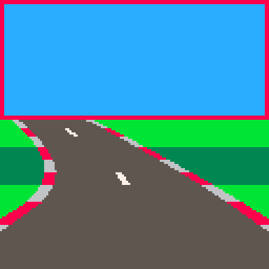
We will draw the tunnel face by drawing rectangles around the mouth of the tunnel.
We'll start by creating a helper function that takes the projected road position and calculates a rectangle describing the tunnel floor, ceiling and walls.
function gettunnelrect(px,py,scale) local w,h=6.4*scale,4*scale local x1=ceil(px-w/2) local y1=ceil(py-h) local x2=ceil(px+w/2) local y2=ceil(py) return x1,y1,x2,y2 end |
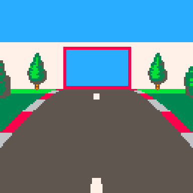
The red rectangle is the "tunnel rectangle". I.e. the mouth of the tunnel.
We're allowing 6.4 units of width for the road, rather than 6, because the red and white shoulder things stick out another 0.2 units each way.
The tunnel will be 4 units high, which is low enough to make the tunnel feel claustrophobic but high enough to be above the camera.
Using this we can implement drawtunnelface:
function drawtunnelface(px,py,scale) -- tunnel mouth local x1,y1,x2,y2=gettunnelrect(px,py,scale) -- tunnel wall top local wh=4.5*scale local wy=ceil(py-wh) -- draw faces if(y1>0)rectfill(0,wy,128,y1-1,7) if(x1>0)rectfill(0,y1,x1-1,y2-1,7) if(x2<128)rectfill(x2,y1,127,y2-1,7) end |
Essentially we're drawing a rectangle that extends from the top of the facing wall down to the top of the tunnel mouth. Then we draw two more rectangles either side of the mouth down to the ground.
The last thing we need to do is restrict the clipping rectangle to the tunnel mouth.
We'll create this function to adjust the clipping rectangle:
function cliptotunnel(px,py,scale,clp) local x1,y1,x2,y2=gettunnelrect(px,py,scale) clp[1]=max(clp[1],x1) clp[2]=max(clp[2],y1) clp[3]=min(clp[3],x2) clp[4]=min(clp[4],y2) end |
And update the tunnel face drawing code in the main drawing loop:
-- draw tunnel face local tnl=road[cnr].tnl if tnl and not ptnl then drawtunnelface(ppx,ppy,pscale) cliptotunnel(ppx,ppy,pscale,clp) setclip(clp) end |
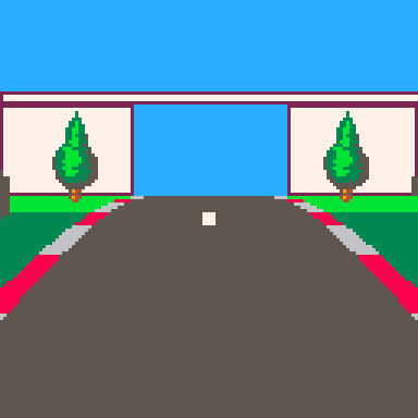
Now we should have a front facing tunnel wall:

Tunnel interior
Next we need to draw the tunnel interior. This will consist of the ceiling, walls and road.
First we need to separate the road drawing code from the ground drawing code, so that we can just draw the road when inside the tunnel. We'll move the ground drawing code out into it's own function:
function drawground(y1,y2,sumct) if(flr(y2)<ceil(y1))return -- draw ground local gndcol=3 if((sumct%6)>=3)gndcol=11 rectfill(0,ceil(y1),128,flr(y2),gndcol) end |
And delete the "draw ground" lines from drawroad.
We'll update the drawing code in the main loop to draw the ground or tunnel interior as appropriate, then draw the road:
-- draw ground/tunnel walls local sumct=getsumct(cnr,seg) if tnl then drawtunnelwalls(px,py,scale,ppx,ppy,pscale,sumct) else drawground(py,ppy,sumct) end -- draw road drawroad(px,py,scale,ppx,ppy,pscale,sumct) |
We draw the tunnel walls by comparing the tunnel rectangles at the start and end of the current segment.
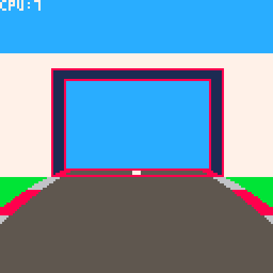
We draw a ceiling rectangle to connect the top of each tunnel rectangle.
Then we draw wall rectangles on each side to connect the left and right sides.
We'll use an alternating colour for effect.
function drawtunnelwalls(px,py,scale,ppx,ppy,pscale,sumct) -- colour local wallcol=0 if(sumct%4<2)wallcol=1 -- draw walls local x1,y1,x2,y2=gettunnelrect(px,py,scale) local px1,py1,px2,py2=gettunnelrect(ppx,ppy,pscale) if(y1>py1)rectfill(px1,py1,px2-1,y1-1,wallcol) if(x1>px1)rectfill(px1,y1,x1-1,py2-1,wallcol) if(x2<px2)rectfill(x2,y1,px2-1,py2-1,wallcol) end |
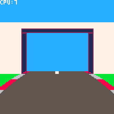
The final step is to update the reduce-clip-region logic in the main drawing loop to handle tunnels.
-- reduce clip region if tnl then cliptotunnel(px,py,scale,clp) else clp[4]=min(clp[4],ceil(py)) end setclip(clp) |
And this completes our tunnel:
Next steps
This is the end of part 3. In part 4 we'll add some cars to overtake.

This tutorial is part 2 of a series. View part 1 here
At the end of part one we had a basic road with corners.
Next we'll add some background objects along the sides of the road. Pseudo-3D racers commonly have objects like trees, houses and signs spaced along the side of the road to make things more interesting.
Adding trees
I've added a few sprites to play with. We'll start by adding this tree along each side, every 3 segments.
|
[128x32] |
Drawing is straightforward.
We can use the projected position and scale of the road at each segment to calculate the position and size of the tree to draw. Then we can pass this to the scale sprite command (sspr), and draw our tree.
For example:
if (sumct%3)==0 then local tx,ty=px-4.5*scale,py local tw,th=1.5*scale,3*scale sspr(8,0,16,32,tx-tw/2,ty-th,tw,th) end |
Will draw a 3x1.5 unit tree 4.5 units to the left of the center of the road (which is far enough to move it off the road).
However!
Because we draw the road front-to-back, we can't just draw the trees at the same time. They must be drawn in back-to-front order so that the near trees appear in front, and it looks correct.
So instead we must create an array of tree sprites:
local sp={} |
And add the position of each tree to the array inside the drawing loop:
if (sumct%3)==0 then
 -- left tree
 local tx,ty=px-4.5*scale,py
 local tw,th=1.5*scale,3*scale
 add(sp,{x=tx,y=ty,w=tw,h=th})

 -- right tree
 tx=px+4.5*scale
 add(sp,{x=tx,y=ty,w=tw,h=th})
end |
After the road is drawn, we have an array of tree positions in front-to-back order.
We can then loop through it backwards to draw them in back-to-front order.
for i=#sp,1,-1 do drawbgsprite(sp[i]) end |
function drawbgsprite(s) sspr(8,0,16,32,s.x-s.w/2,s.y-s.h,s.w,s.h) end |
Putting it all together we get:

Different background types
Now that the basic logic is working, we can extend it to support different background types.
First we need to define the background types, with enough information to position them and draw them at the correct size:
bg_tree={
 img={8,0,16,32},   -- sprite image
 pos={1.5,0},     -- position rel 2 side of road
 siz={1.5,3},     -- size
 spc=3            -- spacing
}
bg_sign={
 img={80,0,32,32},
 pos={.5,0},
 siz={1.5,1.5},
 spc=1,
 flpr=true            -- flip when on right hand side
} |
Now we can assign a background type to each corner. (bgl is for the left hand side, bgr is for the right).
road={
 {ct=10,tu=0,bgl=bg_tree,bgr=bg_tree},
 {ct=6,tu=-.25,bgl=bg_tree,bgr=bg_sign},
 {ct=8,tu=0,bgl=bg_tree,bgr=bg_tree},
 {ct=4,tu=.375,bgl=bg_sign,bgr=bg_tree},
 {ct=10,tu=0.05,bgl=bg_tree,bgr=bg_tree},
 {ct=4,tu=0,bgl=bg_tree,bgr=bg_tree},
 {ct=5,tu=-.25,bgl=bg_tree,bgr=bg_sign},
} |
We'll use this information to populate the "sp" array.
We need to store a little bit more than before, like the width and height and sprite image to draw.
To keep the main loop clean we can put it in a function:
function addbgsprite(sp,sumct,bg,side,px,py,scale)
 if(not bg)return
 if((sumct%bg.spc)~=0)return

 -- find position
 px+=3*scale*side
 if bg.pos then
    px+=bg.pos[1]*scale*side
    py+=bg.pos[2]*scale
 end

 -- calculate size
 local w,h=bg.siz[1]*scale,bg.siz[2]*scale

 -- flip horizontally?
 local flp=side>0 and bg.flpr

 -- add to sprite array
 add(sp,{
  x=px,y=py,w=w,h=h,
  img=bg.img,
  flp=flp
 })
end |
Note that the "side" parameter is -1 for objects on the left hand side and 1 for objects on the right.
We must call it from the main drawing loop. Once for the left hand side and once for the right:
addbgsprite(sp,sumct,road[cnr].bgl,-1,px,py,scale) addbgsprite(sp,sumct,road[cnr].bgr, 1,px,py,scale) |
And finally we need to change the drawbgsprite to handle the new format:
function drawbgsprite(s)
    sspr(
        s.img[1],s.img[2],s.img[3],s.img[4],
        s.x-s.w/2,s.y-s.h,s.w,s.h,
        s.flp)
end |
And now we have trees and signs:

Tweaking sprite scaling
Just a quick tweak to the sprite scaling before we continue. Feel free to skip this section if it doesn't interest you.
You might have noticed the trees sometimes float 1 pixel above the ground.
This is due to how sspr converts its parameters into integers before drawing. The projection and scaling calculations produce position and size values with a fractional component. The sspr command simply discards the fraction and rounds down to the nearest integer, for both the position and size parameters.
I prefer for it to render the pixels between the top and bottom values. For example if a sprite has a top of 1.9 and a bottom of 5.7, I want it to render on scan lines 2,3,4 and 5. This is how the road rendering has been implemented, and it ensures that the rendered segments fit together cleanly with no gaps or overlap.
sspr however will truncate 1.9 to 1 and the height (5.7-1.9=3.8) down to 3, then render it on scan lines 1,2,3,4. So it appears one pixel higher.
But we don't have to let sspr do the rounding. We can perform our own explicit rounding and tell sspr exactly which rows and columns we want our sprite stretched over.
In this case the ceil(1.9) gives me the scan line to start drawing (line 2) and ceil(5.7) gives the scan line to stop drawing (line 6). Subtracting the two gives the number of scan lines I want covered (4), which I can pass to sspr as the height.
And the logic is similar for horizontal columns.
Here's the updated drawbgsprite:
function drawbgsprite(s) local x1=ceil(s.x-s.w/2) local x2=ceil(s.x+s.w/2) local y1=ceil(s.y-s.h) local y2=ceil(s.y) sspr( s.img[1],s.img[2],s.img[3],s.img[4], x1,y1,x2-x1,y2-y1, s.flp) end |
And here's the result:

Bigger background objects
Scaled sprites work really well for background objects, but they can only get so big before we start to run out of Pico8 sprite space. A lot of pseudo 3D racers have nice big roadside objects like buildings and bridges to make things varied and interesting.
Pico8 has the sprite "map" where you can layout sprites to make much larger objects. So if we can scale sections of the map to the screen this would solve our problem. But Pico8 does not have a built in "scale map" command like sspr does for sprites.
Fortunately though, we can roll our own.
The idea is to loop over the map tiles and use the "mget" function to get the sprite for each position in the map. Then we can calculate its position and size on screen and use sspr to draw it.
function smap(mx,my,mw,mh,dx,dy,dw,dh)
 -- tile size on screen
 local tw,th=dw/mw,dh/mh

 -- loop over map tiles
 for y=0,mh-1 do
  for x=0,mw-1 do

   -- lookup sprite
   local s=mget(mx+x,my+y)

   -- don't draw sprite 0
   if s~=0 then

    -- sprite row and column index
    -- use to get sprite image coords
    local sc,sr=s%16,flr(s/16)      -- 16 sprites per row
    local sx,sy=sc*8,sr*8         -- 8x8 pixels per sprite

    -- sprite position on screen
    local x1=ceil(dx+x*tw)
    local y1=ceil(dy+y*th)
    local x2=ceil(dx+x*tw+tw)
    local y2=ceil(dy+y*th+th)

    -- scale sprite
    sspr(sx,sy,8,8,
         x1,y1,x2-x1,y2-y1)
   end
  end
 end
end |
mx,my,mw,mh are the map coordinates in cells. dx,dy,dw,dh are the screen coordinates to draw.
We can test this function by typing (in immediate mode):
smap(0,0,8,5,0,0,128,128) |
Which should draw a scaled house across the screen.
Armed with our new function, we can add some houses to our map. This takes a little bit of plumbing.
First we define a background type for it:
bg_house={
 mp={0,0,8,5},           -- map image (x,y,w,h in tiles)
 pos={3.5,0},
 siz={6,3.5},
 spc=4
} |
And add some houses to the end of our road:
road={
 {ct=10,tu=0,bgl=bg_tree,bgr=bg_tree},
 {ct=6,tu=-.25,bgl=bg_tree,bgr=bg_sign},
 {ct=8,tu=0,bgl=bg_tree,bgr=bg_tree},
 {ct=4,tu=.375,bgl=bg_sign,bgr=bg_tree},
 {ct=10,tu=0.05,bgl=bg_tree},
 {ct=4,tu=0,bgl=bg_tree,bgr=bg_tree},
 {ct=5,tu=-.25,bgl=bg_tree,bgr=bg_sign},
 {ct=12,tu=0,bgl=bg_house,bgr=bg_house},
 {ct=8,tu=-.5,bgl=bg_house,bgr=bg_sign},
 {ct=8,tu=.5,bgl=bg_sign,bgr=bg_house},
} |
We need to copy the "mp" property when we write the entry into the "sp" sprite array, in the "addbgsprite" function:
 -- add to sprite array
 add(sp,{
  x=px,y=py,w=w,h=h,
  img=bg.img,
  mp=bg.mp,
  flp=flp
}) |
The last step is to update "drawbgsprite" to call our smap function when it receives a sprite with an "mp" property:
function drawbgsprite(s)
 if s.mp then
  smap(s.mp[1],s.mp[2],s.mp[3],s.mp[4],
       s.x-s.w/2,s.y-s.h,s.w,s.h)
 else
  local x1=ceil(s.x-s.w/2)
  local x2=ceil(s.x+s.w/2)
  local y1=ceil(s.y-s.h)
  local y2=ceil(s.y)
    sspr(s.img[1],s.img[2],s.img[3],s.img[4],
            x1,y1,x2-x1,y2-y1,
            s.flp)
 end
end |
Putting it all together gives:

It should be kept in mind that scaling a map results in a lot of sspr calls. Our 8x5 tile house has 40 sprites to draw (well really 38, as it skips the blank top left and right tiles). A larger building could have 100,200 or more.
So it's worth keeping an eye on the CPU usage to make sure Pico-8 isn't going to max out, and maybe space larger objects out a bit more.
Having said that, we're still only at 17% CPU tops, so Pico-8 definitely has the ability to handle a decent amount of scenery.
Bridges and beams
To finish off let's add some metal beams for the player to drive underneath. This will be a centered background object, which means it's technically in the middle of the road. However because the beam object is wider than the road and is essentially bridge shaped, the camera will drive through/underneath it, instead of crashing into it.
We have most of what we need already. We'll define a background type:
bg_beams={
 mp={8,0,16,8},
 siz={10,5},
 spc=2
} |
And add it to our road, using "bgc" to indicate it's a centered background object.
road={
 {ct=10,tu=0,bgl=bg_tree,bgr=bg_tree},
 {ct=6,tu=-.25,bgl=bg_tree,bgr=bg_sign},
 {ct=8,tu=0,bgl=bg_tree,bgr=bg_tree},
 {ct=4,tu=.375,bgl=bg_sign,bgr=bg_tree},
 {ct=10,tu=0.05,bgl=bg_tree},
 {ct=4,tu=0,bgl=bg_tree,bgr=bg_tree},
 {ct=5,tu=-.25,bgl=bg_tree,bgr=bg_sign},
 {ct=15,tu=0,bgc=bg_beams},
 {ct=12,tu=0,bgl=bg_house,bgr=bg_house},
 {ct=8,tu=-.5,bgl=bg_house,bgr=bg_sign},
 {ct=8,tu=.5,bgl=bg_sign,bgr=bg_house},
} |
In the main drawing loop, we'll add another call to "addbgsprite" for centered objects:
-- add background sprites addbgsprite(sp,sumct,road[cnr].bgl,-1,px,py,scale) addbgsprite(sp,sumct,road[cnr].bgr, 1,px,py,scale) addbgsprite(sp,sumct,road[cnr].bgc, 0,px,py,scale) |
By passing 0 as the "side" parameter we cancel out any horizontal positioning, so that it ends up in the middle of the road.
And that's all we need to do:
Next steps
And that's it for part 2. Part 3 is about creating hills and tunnels.

Reposting this in carts, because it's as finished as it's ever going to be :-).
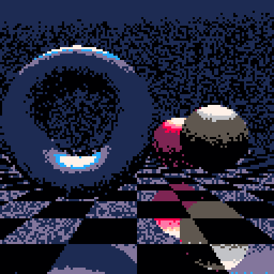
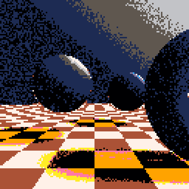
This is a little SDF ray marcher I've been playing with.
It renders two randomly placed spheres and a torus above a checker-board plane in different colours. Often one of them is reflective.
The code is ugly as heck, and the specular highlights are completely wrong, but it occasionally spits out something pretty imo.
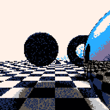
Update: Changed to use sqrt() again, as it's much more accurate in v0.2.0

I felt like ray marching a signed distance field in PICO-8.
(Don't ask me why..).

Pseudo 3D racing games are fun. They have a cool retro arcade feel, with a good sense of speed, and can run on low end hardware. Plus they're pretty straightforward to implement - and satisfying.
There are lots of different ways to write a pseudo 3D racer, but I'm just going to show you how I do it.
This is the method I used for Loose Gravel, and can render corners, hills, tunnels and background sprites in an efficient manner. It doesn't need any 3D drawing hardware, just basic 2D rectangles, lines, scaled sprites and rectangular clip regions. Pico-8 can do all of these.
Defining the road
The road is made out of "corners" (for our purposes we will call straight bits "corners" as well). Corners need to curve in the direction the road turns, so we will simulate this by building them out of smaller straight "segments".
We can define the track as an array of these corners.
road={
 {ct=10,tu=0},
 {ct=6,tu=-1},
 {ct=8,tu=0},
 {ct=4,tu=1.5},
 {ct=10,tu=0.2},
 {ct=4,tu=0},
 {ct=5,tu=-1},
} |
Each corner has a segment count "ct" and a value indicating how much the direction turns between each segment "tu".
So tu=0 creates a straight piece, tu=1 will turn to the right, -1 left etc.
For simplicity we'll ignore hills and valleys for now.
Drawing the road
We will draw the road by walking a 3D "cursor" along it and drawing the road at each point.
We'll define the cursor like this:
local x,y,z=0,1,1 |
We will start drawing the road slightly in front (z=1) and below (y=1) the camera position.
Note: I use x=right, y=down, z=into the screen as my coordinate system. I find this easiest to work with, having x and y in the same direction as on the screen and keeping z coordinates positive.
The direction of the road is another 3D vector:
local xd,yd,zd=0,0,1 |
So initially the road will point straight forward (zd=1).
The direction will be added to the cursor's 3D position to move from the current segment to the start of the next. To keep the maths simple we're using segments of length 1.
We also need to track which corner and segment we are drawing:
local cnr,seg=1,1 |
The main drawing loop will draw 30 segments of the road from the starting position, as follows:
- Draw the road at the current position
- Move to the next position in 3D space
- Adjust the direction based on how the road turns
- Advance to the next segment (and corner if applicable)
Putting this together, gives us something like this:

Click "code" up above to view the code.
It's just a static boring line for now, but the basic logic is there. I was pretty vague about what "draw the road" means so we're just drawing a line to the x and z coordinates of the "cursor" for now.
We can see that the road goes straight for a bit then turns to the left as it moves down the screen.
We're "adjusting the direction" by adding the turn amount for the current corner to the X coordinate of our direction vector:
xd+=road[cnr].tu |
which means we're actually skewing the road rather than rotating it. This is part of the "pseudo" in our pseudo 3D - the difference is if we were using proper rotation the road would eventually turn around and start coming back towards us - if it turned far enough - whereas with skewing it just keeps stretching out more and more horizontally.
Although less realistic, skewing is much simpler to implement, and means that the road will always face away from the camera, which makes drawing things in the right order a lot simpler. And as long as the corners aren't too sharp it's an acceptable approximation.
Making it 3D
The key making this 3D is called perspective projection.
This converts a 3D coordinate into a 2D screen coordinate. I won't bore you with the mathematics - there are plenty of other places you can find this information if you really want to.
The important thing is the formula, which is:
- px=x*64/z+64
- py=y*64/z+64
This gives a 90 degree field of view (FOV). Replacing the 64 in 64/z with a smaller value would give a wider FOV, or a larger value would give a narrower FOV. We'll stick with 64 however. The +64 moves everything into the center of the screen.
64/z is also a useful value to keep, because it is the scale factor for anything drawn at that position, such as scaled sprites, or the road width. So the project function will return this too:
function project(x,y,z) local scale=64/z return x*scale+64,y*scale+64,scale end |
With this we can replace the line drawing code in the main loop:
-- project local px,py,scale=project(x,y,z) -- draw road local width=3*scale line(px-width,py,px+width,py) |
The projection allows us to draw a horizontal line 6 units wide, scaled appropriately for the 3D position.
This produces something a little more like looking down a road.

Adding movement
Right now the road is static, because it is always drawn from the same position.
To get the sensation of movement we need to simulate a camera moving down the road, and draw it from the camera's position.
So we'll declare the camera:
camcnr,camseg=1,1 |
And change "cursor" in the _draw() function to start from the camera position:
local cnr,seg=camcnr,camseg |
We can use the same logic to advance the camera to the next segment as we do for the "cursor" when drawing, by moving it out into a function:
function advance(cnr,seg) seg+=1 if seg>road[cnr].ct then seg=1 cnr+=1 if(cnr>#road)cnr=1 end return cnr,seg end |
This advances to the next segment in the corner, and if necessary the next corner in the road, looping around to the first corner if required.
Then we call it from the _draw() function:
-- advance along road cnr,seg=advance(cnr,seg) |
And use it to advance the camera in _update():
function _update() camcnr,camseg=advance(camcnr,camseg) end |
Putting it together we get:

Which sort-of looks like movement, but isn't totally convincing.
The camera is moving one full segment per rendered frame, which means the segment lines are rendered at the same distance each time.
We need to move less than a full segment per rendered frame, which means we need to track the camera position relative to the current segment:
camx,camy,camz=0,0,0 |
Now we can advance the camera by less than a full segment length:
function _update() camz+=0.1 if camz>1 then camz-=1 camcnr,camseg=advance(camcnr,camseg) end end |
Inside _draw() we start drawing relative to the camera position, by subtracting the camera coordinates from the starting coordinates.
local x,y,z=-camx,-camy+1,-camz+1 |
With these changes the forward movement feels more convincing:

But now cornering feels janky.
This is because the camera is always aligned exactly with the segment it is on, so when it moves to the next segment it snaps sharply.
To counter this we need to turn the camera smoothly towards the next segment's angle as it progresses down the current segment. We can compute this angle in _draw() as:
local camang=camz*road[camcnr].tu |
Then subtract it from the initial cursor direction:
local xd,yd,zd=-camang,0,1 |
This gives some improvement:

It's still not 100% though - there's still some horizontal juddering.
This can be a little tricky to understand the cause of.
The gist of it is that by turning the camera, we're skewing the first segment will be rendered. But when we calculate the cursor position relative to the camera, we're using the un-skewed camera offset. So when we draw the road forward again, the part that should pass through the camera point will actually be skewed left or right of it. This makes the camera appear to diverge from the path of the road as it moves towards the end of the segment. It then snaps back into the center when it progresses to the next segment.
To fix this issue we need to first skew the camera position in the "cursor" direction, then calculate the cursor position relative to the skewed camera position.
We'll start by creating a basic skew function:
function skew(x,y,z,xd,yd) return x+z*xd,y+z*yd,z end |
Essentially we're skewing the Z axis from (0,0,1) to (xd,yd,1).
We'll need to re-order the "cursor" setup code in _draw(), so that the direction is calculated first.
I.e. move this bit in front of the initial x,y,z calculation:
-- direction local camang=camz*road[camcnr].tu local xd,yd,zd=-camang,0,1 |
Then we can calculate the skewed camera position:
local cx,cy,cz=skew(camx,camy,camz,xd,yd) |
And calculate the initial "cursor" position relative to the skewed camera:
local x,y,z=-cx,-cy+1,-cz+1 |
This finally gives us nice smooth camera movement:

This is the core road drawing algorithm for a pseudo 3D racer.
The last step is to simply clean up the rendering so it's not just white lines on black.
With a little bit of work we can turn it into something like this:
I won't go into too much detail here - you can refer to the cartridge code for specifics - I'll just touch on a few basic points.
To draw the road we need to render a trapezium (also known as a trapezoid). Essentially we're joining the horizontal lines together and filling them in. Pico-8 doesn't have a built in trapezium drawing function, but we can roll our own by stacking 1-pixel high rectangles.
We use alternating colours to communicate speed, which is a common technique in pseudo 3D racers. The easiest way to do this is to track how many segments we are along the road as a whole. Then we can use the modulo operator (%) to determine whether we are on an odd or even segment, or every 6th segment etc, and use that to select a colour.
We pre-calculate this (as "sumct") for each corner of the road in an _init() function. This makes it easy to calculate for any corner and segment:
function getsumct(cnr,seg) return road[cnr].sumct+seg-1 end |
We use this to alternate the ground colour every 3 segments.
We don't have to stop at just drawing a plain gray road. The projected positions, trapezium drawing routine and colour alternation give us the tools we need to draw other road features. So we've drawn road markings as a thin trapezium every 4 segments in the middle of the road, and shoulder barrier things on the sides of the road, alternating red and white every other segment.
With the basic rendering in place this is a good time to tweak the parameters to get the right look and feel. The following adjustments were made:
- Moved the road start point to (0,2,2) in front of the camera
- Reduced the corner "tu" values, as the corners were too sharp
- Increased the movement speed from 0.1 to 0.3
Next steps
This feels like a good place to leave the first tutorial.
In part 2 we'll cover drawing roadside objects (and overhead objects) using scaled sprites.
I just noticed the += shorthand doesn't work the way I expected with comma separated values.
For example:
x,y,z=1,2,3 x,y,z+=10,20,30 |
Sets x to 11 as expected, but y and z are set to 20 and 30 respectively, rather than 22 and 33.
Should the last line be equivalent to:
x+=10 y+=20 z+=30 |
?
Or is there some reason I'm missing?

I'm sure this has been done dozens of times already, but I thought it would be fun to give it a go.
So here's a simple Wolfenstein 3D style ray-caster.
There's no game-play at all, you can just move around.
You can edit the level in the pico8 map editor (make sure it is always enclosed, otherwise you'll get an infinite loop - rays only terminate when they hit a wall).
Update: Cleaned up & optimised code. Added textured ceiling and floor.
|
40
|

This is Loose Gravel! A pseudo-3d racer that started as a proof of concept, and gradually grew into something of a game.
If you're curious, you can view the progress here.
Pretty self explanatory. Choose a course and try to overtake the other cars in 3 laps to win.
Courses are randomly generated but have their own unique parameters and feel.
I was planning to add a tournament mode (and some more tracks), but I ran out of cart space (so that means it's finished! :) )
Tip: If you tap the up arrow you will keep accelerating until you hit something or drive off the road. You don't need to hold it down.
Enjoy.
-Mot
Update: Replace scaled map routine with tline version

I wanted to share a little work-in-progress I've been tinkering on.
Dungeon guy doesn't know what he's searching for. Maybe treasure? Maybe a way out? Maybe dungeon girl?
All he knows is to keep searching.
Levels are randomly generated and get progressively larger.
The only objective so far is to find the key and the exit door.