Table of Contents
Advertisement
Advertisement
Table of Contents
Troubleshooting

Related Manuals for DFI LanParty UT RDX200 series


Summary of Contents for DFI LanParty UT RDX200 series
-
Page 1: System Board
System Board User’s Manual 935-D200C1-000G 87730551... - Page 2 Copyright This publication contains information that is protected by copyright. No part of it may be reproduced in any form or by any means or used to make any transformation/adaptation without the prior written permission from the copyright holders. This publication is provided for informational purposes only. The manufacturer makes no representations or warranties with respect to the contents or use of this manual and specifically disclaims any express or implied warranties of merchantability or fitness for any...
-
Page 3: Fcc And Doc Statement On Class B
FCC and DOC Statement on Class B This equipment has been tested and found to comply with the limits for a Class B digital device, pursuant to Part 15 of the FCC rules. These limits are designed to provide reasonable protection against harmful interference when the equipment is operated in a residential installation. -
Page 4: Table Of Contents
Table of Contents About this Manual................Warranty..................... Static Electricity Precaution..............Safety Measures..................About the Package................Before Using the System Board............Français....................Deutsch....................Español....................Ðóññêèé ÿçûê.................... Chapter 1 - Introduction..............Specifications........................... Special Features of the System Board..............Chapter 2 - Hardware Installation............ System Board Layout ...................... -
Page 5: About This Manual
About this Manual This user’s manual contains detailed information about the system board. If, in some cases, some information doesn’t match those shown in the multilingual manual, the multilingual manual should al- ways be regarded as the most updated version. The multilingual manual is included in the system board package. -
Page 6: Static Electricity Precaution
Introduction Static Electricity Precautions It is quite easy to inadvertently damage your PC, system board, components or devices even before installing them in your system unit. Static electrical discharge can damage computer components without causing any signs of physical damage. You must take extra care in handling them to ensure against electrostatic build-up. -
Page 7: About The Package
Introduction About the Package The system board package contains the following items. If any of these items are missing or damaged, please contact your dealer or sales representative for assistance. One system board One Karajan audio module Two IDE round cables One floppy round cable Four Serial ATA data cables Two Serial ATA power cables... -
Page 8: Français
Introduction Français Caractéristiques et Spécifications Processeur • AMD Athlon 64 FX / Athlon 64 / Sempron • Interface HyperTransport 2000MT/s • Socket 939 Chipset • ATI chipset ® Pont nord: ATI Radeon Xpress 200 CrossFire Pont sud: ATI SB450 Mémoire Système •... - Page 9 Introduction • Sorties de niveau de lignes stéréo vraies • Interface entrée/sor tie S/PDIF Fonctionnalités Onboard LAN • Deux Gigabit LAN - Marvell 88E8053 PCI Express et Marvell 88E8001 PCI • Suppor te IEEE 802.3 (10BASE-T), 802.3u (100BASE-TX) et 802.3ab (1000BASE-T) •...
-
Page 10: Deutsch
Introduction Deutsch Leistungsmerkmale und Technische Daten Prozessor • AMD Athlon 64 FX / Athlon 64 / Sempron • Interface HyperTransport 2000MT/s • Socket 939 Chipset • ATI chipset ® Nordbrücke: ATI Radeon Xpress 200 CrossFire Südbrücke: ATI SB450 Systemspeicher • 4 DDR-SDRAM-DIMM- Fassungen mit 184poligem Anschlußstecker •... - Page 11 Introduction 6 Audio-Anschlußbuchsen 1 interne Audioanschlüsse (CD-in) und 1 Frontaudioanschluß • Naturgetreue Stereo-Leitungspegel-Ausgabe • S/PDIF-In/Aus-Schnittstelle Merkmale des LAN auf Platine • Zwei Gigabit LAN - Marvell 88E8053 PCI Express und Marvell 88E8001 PCI LAN • Unterstützt IEEE 802.3 (10BASE-T), 802.3u (100BASE-TX) und 802.3ab (1000BASE-T) •...
-
Page 12: Español
Introduction Español Características y Especificaciones Procesador • AMD Athlon 64 FX / Athlon 64 / Sempron • Interface de HyperTransport 2000MT/s • Socket 939 Chipset • ATI chipset ® Puente norte: ATI Radeon Xpress 200 CrossFire Puente sur: ATI SB450 Memoria de Sistema •... - Page 13 Introduction • Auténtico salidas de nivel de línea estéreo • Interfáz de S/PDIF-in/out Características de LAN Interno • Dos Gigabit LAN - Marvell 88E8053 PCI Express y Marvell 88E8001 PCI • Sopor ta IEEE 802.3 (10BASE-T), 802.3u (100BASE-TX) y 802.3ab (1000BASE-T) •...
-
Page 14: Ðóññêèé Ÿçûê
Introduction Ðóññêèé ÿçûê Ðóññêèé ÿçûê Ðóññêèé ÿçûê Ðóññêèé ÿçûê Ðóññêèé ÿçûê Õàðàêòåðèñòèêè è ñâîéñòâà Õàðàêòåðèñòèêè è ñâîéñòâà Õàðàêòåðèñòèêè è ñâîéñòâà Õàðàêòåðèñòèêè è ñâîéñòâà Õàðàêòåðèñòèêè è ñâîéñòâà Ï ð î ö å ñ ñ î ð Ï ð î ö å ñ ñ î ð Ï... - Page 15 Introduction 6 ãíåçäà äëÿ çâóêà, 1 ðàçúåì CD-in è 1 ïåðåäíèé àóäèî ðàçúåì • Íàñòîÿùèé ëèíåéíûé ñòåðåî âûõîä • èíòåðôåéñà S/PDIF-in è S/PDIF-out Âñòðîåííûå ñåòåâûå ôóíêöèè Âñòðîåííûå ñåòåâûå ôóíêöèè Âñòðîåííûå ñåòåâûå ôóíêöèè Âñòðîåííûå ñåòåâûå ôóíêöèè Âñòðîåííûå ñåòåâûå ôóíêöèè • 2 Gigabit LAN - Marvell 88E8053 PCI Express è Marvell 88E8001 PCI •...
-
Page 16: Chapter 1 - Introduction
Introduction Chapter 1 - Introduction Specifications Processor • AMD Athlon 64 FX / Athlon 64 / Sempron • Socket 939 Front Side Bus • 2000MT/s HyperTransport interface Chipset • ATI chipset ® Northbridge: ATI Radeon Xpress 200 CrossFire Southbridge: ATI SB450 System Memory •... - Page 17 Introduction BIOS • Award BIOS • CMOS Reloaded • CPU/DRAM overclocking • CPU/DRAM/Chipset overvoltage • 4Mbit flash memory Energy Efficient Design • Suppor ts ACPI specification and OS Directed Power Management • Supports ACPI STR (Suspend to RAM) function • Wake-On-Events include: Wake-On-PS/2 Keyboard/Mouse Wake-On-USB Keyboard/Mouse Wake-On-Ring...
- Page 18 Introduction Onboard LAN Features • Dual Gigabit LAN - Marvell 88E8053 PCI Express and Marvell 88E8001 PCI LAN • Fully compliant to IEEE 802.3 (10BASE-T), 802.3u (100BASE-TX) and 802.3ab (1000BASE-T) standards • Integrated power management functions • Supports wire for management IDE Interface •...
- Page 19 Introduction I/O Connectors • 1 connector for 2 additional external USB 2.0/1.1 ports • 1 connector for 1 external IEEE 1394 port • 1 connector for 1 external serial port • 1 connector for the Karajan audio module • 1 front audio connector for external line-out and mic-in jacks (on the Karajan audio module) •...
-
Page 20: Special Features Of The System Board
Introduction Special Features of the System Board AMD Athlon The system board supports the AMD Athlon 64 processor. AMD Athlon 64 provides superior computing for many software applications by allowing both 32-bit and 64-bit applications to run simultaneously on the same platform. The operating system and software are able to process more data and access a tremendous amount of memory which improves the overall system performance. - Page 21 Introduction CPU Overheat Protection CPU Overheat Protection has the capability of monitoring the CPU’s temperature during system boot up. Once the CPU’s temperature exceeded the temperature limit pre-defined by the CPU, the system will automatically shutdown. This preventive measure has been added to protect the CPU from damage and insure a safe computing environment.
- Page 22 Introduction Serial ATA Interface with RAID Serial ATA is a storage interface that is compliant with SATA 1.0 specification. With speed of up to 1.5Gb/s, it improves hard drive performance faster than the standard parallel ATA whose data transfer rate is 100MB/s. The ATI SB450 chip supports RAID 0 and RAID 1 while the Silicon Image Sil 3114 chip (LANPARTY UT RDX200 CF-DR only) supports RAID 0, RAID 1, RAID 0+1 and RAID 5.
- Page 23 Introduction Dual Function Power Button Depending on the setting in the “Soft-Off By PBTN” field of the Power Management Setup, this switch will allow the system to enter the Soft-Off or Suspend mode. Wake-On-Ring This feature allows the system that is in the Suspend mode or Soft Power Off mode to wake-up/power-on to respond to calls coming from an external modem or respond to calls from a modem PCI card that uses the PCI PME (Power Management Event) signal to...
- Page 24 Introduction Wake-On-USB Keyboard/Mouse This function allows you to use a USB keyboard or USB mouse to wake up a system from the S3 (STR - Suspend To RAM) state. Important: If you are using the Wake-On-USB Keyboard/Mouse function for 2 USB ports, the 5VSB power source of your power supply must support ≥...
- Page 25 Introduction AC Power Failure Recovery When power returns after an AC power failure, you may choose to either power-on the system manually, let the system power-on automatically or return to the state where you left off before power failure occurs.
-
Page 26: Chapter 2 - Hardware Installation
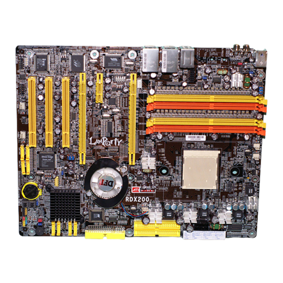
Hardware Installation Chapter 2 - Hardware Installation System Board Layout Silicon Image Sil3114 and SATA 5 to SATA 8 are supported in the LANPARTY UT RDX200 CF-DR model only. -
Page 27: System Memory
Hardware Installation Warning: Electrostatic discharge (ESD) can damage your system board, processor, disk drives, add-in boards, and other components. Perform the upgrade instruction procedures described at an ESD workstation only. If such a station is not available, you can provide some ESD protection by wearing an antistatic wrist strap and attaching it to a metal part of the system chassis. -
Page 28: Hardware Installation
Hardware Installation The system board supports the following memory interface. Single Channel (SC) Data will be accessed in chunks of 64 bits (8B) from the memory channels. Dual Channel (DC) Data will be accessed in chunks of 128 bits from the memory channels. - Page 29 Hardware Installation The integrated memory controller in AMD's 64-bit Socket 939 series CPU will directly catch data transmission from DDR RAM without passing through the Northbridge. Therefore when using 4 identical double side DIMMs or using 2 DIMMs in non-dual channels, the memory speed will reduce to DDR333.
-
Page 30: Installing The Dim Module
Hardware Installation Installing the DIM Module A DIM module simply snaps into a DIMM socket on the system board. Pin 1 of the DIM module must correspond with Pin 1 of the socket. Notch Pin 1 1. Pull the “tabs” which are at the ends of the socket to the side. 2. -
Page 31: Cpu
Hardware Installation Overview The system board is equipped with a surface mount 939-pin CPU socket. This socket is exclusively designed for installing an AMD CPU. Installing the CPU 1. Make sure the PC and all other peripheral devices connected to it has been powered down. - Page 32 Hardware Installation 4. Unlock the socket by pushing the lever sideways, away from the socket, then lifting it up to a 90 angle. Make sure the lever is lifted to at least this angle otherwise the CPU will not fit in properly. Lever 5.
- Page 33 Hardware Installation 6. Insert the CPU into the socket until it is seated in place. The CPU will fit in only one orientation and can easily be inserted without exerting any force. Important: Do not force the CPU into the socket. Forcing the CPU into the socket may bend the pins and damage the CPU.
- Page 34 Hardware Installation Installing the Fan and Heat Sink The CPU must be kept cool by using a CPU fan with heat sink. Without sufficient air circulation across the CPU and heat sink, the CPU will overheat damaging both the CPU and system board. Note: •...
- Page 35 Hardware Installation 3. Place the heat sink on top of the CPU. Now hook one side of the retention clip onto the retention module base by fitting the holes on the retention clip into the retaining tabs of the retention module base.
- Page 36 Hardware Installation 4. Hook the other side of the retention clip (the one near the retention lever) so that the holes on the retention clip also fit into the retaining tabs of the retention module base. Note: You will not be able to secure the fan and heat sink assembly in place if it did not fit properly onto the retention module base.
-
Page 37: Jumper Settings
Hardware Installation Jumper Settings Clear CMOS Data 1-2 On: Normal 2-3 On: (default) Clear CMOS Data If you encounter the following, a) CMOS data becomes corrupted. b) You forgot the supervisor or user password. c) You are unable to boot-up the computer system because the processor’s clock was incorrectly set in the BIOS. - Page 38 Hardware Installation 4. After powering-on the system, press <Del> to enter the main menu of the BIOS. 5. Select the Genie BIOS Setting submenu and press <Enter>. 6. Set the processor’s clock to its default setting or an appropriate bus clock. Refer to the Genie BIOS Setting section in chapter 3 for more information.
- Page 39 Hardware Installation PS/2 Power Select 1-2 On: 5V 2-3 On: 5VSB (default) JP7 is used to select the power of the PS/2 keyboard/mouse port. Selecting 5VSB will allow you to use the PS/2 keyboard or PS/2 mouse to wake up the system. BIOS Setting Configure the PS/2 keyboard/mouse wake up function in the Integrated Peripherals submenu of the BIOS.
-
Page 40: Usb Power Select
Hardware Installation USB Power Select USB 1-6 (JP5) 1-2 On: 5V 2-3 On: 5VSB (default) USB 7-8 (JP6) 1-2 On: 5V 2-3 On: 5VSB (default) JP5 and JP6 are used to select the power of the USB ports. Selecting 5VSB will allow you to use the USB keyboard or USB mouse to wake up the system.. - Page 41 Hardware Installation Speaker On/Off Select Buzzer 2-3 On: 1-2 On: Speaker On Speaker Off (default) The system board is equipped with a buzzer which serves as the PC’s speaker. By default the buzzer is “on” allowing you to hear the system’s beep messages and warnings.
- Page 42 Hardware Installation S/PDIF-out Settings JP52 2-3 On: 1-2 On: S/PDIF-out via S/PDIF-out via ALC882 JP52 is used to select the controller that will send signal to the S/PDIF-out port.
-
Page 43: Rear Panel I/O Ports
Hardware Installation Rear Panel I/O Ports Front R/L (Line-out) PS/2 Line-in Mic-in LAN 1 LAN 2 Mouse 1394_1 S/PDIF-in PS/2 USB 1-2 USB 3-4 USB 5-6 S/PDIF-out Rear R/L Center/ Side R/L Subwoofer Karajan audio module The rear panel I/O ports consist of the following: •... - Page 44 Hardware Installation PS/2 Mouse and PS/2 Keyboard Ports PS/2 Mouse PS/2 Keyboard The system board is equipped with an onboard PS/2 mouse (Green) and PS/2 keyboard (Purple) ports - both at location CN2 of the system board. The PS/2 mouse port uses IRQ12. If a mouse is not connected to this port, the system will reserve IRQ12 for other expansion cards.
- Page 45 Hardware Installation S/PDIF-in/out Jacks S/PDIF-in S/PDIF-out SPDIF out SPDIF in The system board is equipped with an onboard S/PDIF-in RCA jack (red) and a S/PDIF-out RCA jack (yellow) at locations CN5 and CN7 respectively. The S/PDIF connector at location J3 is used to connect to optical S/PDIF ports.
- Page 46 Hardware Installation Karajan Audio Module Line-in Mic-in Front R/L (Line-out) Rear R/L Side R/L Center/ Subwoofer Karajan audio module Karajan audio connector Installing the Karajan Audio Module The system board comes with the Karajan audio module already installed on the board. The module is stabilized by means of the module holder.
- Page 47 Hardware Installation To install: 1. Fit the module holder onto the Karajan audio module. 2. Align the module’s plugs above the mounting holes then insert the plugs from the top through to the bottom of the system board. While at it, the 14-pin connector at the solder side of the module must also insert into the Karajan audio connector at location J7 of the system board.
- Page 48 Hardware Installation Mounting holes Karajan audio connector (J7) Karajan Audio Jacks • Line-in (Light Blue) This jack is used to connect any audio devices such as Hi-fi set, CD player, tape player, AM/FM radio tuner, synthesizer, etc. • Front Right/Left Jack - Line-out (Lime) This jack is used to connect to the front right and front left speakers of the audio system.
- Page 49 Hardware Installation Front Audio The front audio connector (J4) on the Karajan audio module allows you to connect to the line-out and mic-in jacks that are at the front panel of your system. Using this connector will disable the rear au- dio’s line-out and mic-in functions.
- Page 50 Hardware Installation IEEE 1394 1394_1 1 0 9 Ground +12V (fused) +12V (fused) TPB- TPB+ Ground Ground TPA+ TPA- 1394_2 The system board is equipped with an onboard IEEE 1394 port at location CN3 (IEEE 1394_1) of the system board. It is also equipped with an IEEE 1394 connector at location J8 (1394_2) for connecting an additional 1394 device.
-
Page 51: Universal Serial Bus Ports
Hardware Installation Universal Serial Bus Ports USB 2 USB 1 USB 4 USB 3 USB 6 USB 5 USB 7-8 The system board supports 8 USB 2.0/1.1 ports. USB allows data exchange between your computer and a wide range of simultaneously accessible external Plug and Play peripherals. - Page 52 Hardware Installation Driver Installation You may need to install the proper drivers in your operating system to use the USB device. Refer to your operating system’s manual or documentation for more information. Refer to chapter 4 for more information about installing the USB 2.0 driver.
-
Page 53: Rj45 Lan Port
Hardware Installation RJ45 LAN Port LAN 1 LAN 2 LAN 1 which is controlled by the Marvell 88E8053 Gigabit PCI Express x1 chip is at location CN4 and LAN 2 which is controlled by the Marvell 88E8001 Gigabit PCI chip is at location CN6. LAN allows the system board to connect to a local area network by means of a network hub. -
Page 54: I/O Connectors
Hardware Installation I/O Connectors CD-in Internal Audio Connector Ground Ground Left audio Right audio channel channel Audio codec Line-in Front R/L Mic-in Center/Subwoofer Rear R/L Side R/L The CD-in (J2) connector on the Karajan audio module used to receive audio from a CD-ROM drive, TV tuner or MPEG card. -
Page 55: Floppy Disk Drive Connector
Hardware Installation Floppy Disk Drive Connector The system board is equipped with a 90 floppy disk drive connector that supports two standard floppy disk drives. To prevent improper floppy cable installation, the floppy disk header has a keying mechanism. The 34-pin connector on the floppy cable can be placed into the header only if pin 1 of the connector is aligned with pin 1 of the header. -
Page 56: Serial Ata Connectors
Hardware Installation Serial ATA Connectors Four Serial ATA ports supported by the ATI SB450 chip (LANPARTY UT RDX200 CF-D only) SATA 1 (J2) SATA 2 (J10) SATA 3 (J11) SATA 4 (J13) • SATA speed up to 1.5Gb/s • RAID 0 and RAID 1 Connecting Serial ATA Cables Connect one end of the Serial ATA cable to the Serial ATA connector and the other end to your Serial ATA device. - Page 57 Hardware Installation 5. When the system powers-up, the ATI BIOS status message screen will appear. Press the <F4> key to enter the utility. The utility allows you to build a RAID system on Serial ATA drives. 6. Normally you do not need to separately install the ATI RAID driver.
- Page 58 Hardware Installation Four Serial ATA ports supported by the Silicon Image Sil 3114 chip (LANPARTY UT RDX200 CF-DR only) 7 SATA 8 (J29) SATA 5 (J26) SATA 6 (J27) 7 SATA 7 (J28) SATA speed up to 1.5Gb/s RAID 0, RAID 1, RAID 0+1 and RAID 5 Connecting Serial ATA Cables Connect one end of the Serial ATA cable to the Serial ATA connector and the other end to your Serial ATA device.
- Page 59 Hardware Installation 3. Set the “Sil3114 S-ATA RAID Control” field to “SATA RAID”. 4. Save and exit the BIOS then reboot the PC. 5. When the system powers-up, the Sil3114 SataRAID BIOS status message screen will appear. Press the <Ctrl-S> or <F4> key to enter the utility.
-
Page 60: Ide Disk Drive Connector
Hardware Installation IDE Disk Drive Connector IDE 2 IDE 1 The system board is equipped with two shrouded PCI IDE headers that will interface four Enhanced IDE (Integrated Drive Electronics) disk drives. To prevent improper IDE cable installation, each shrouded PCI IDE header has a keying mechanism. - Page 61 Hardware Installation Note: Refer to your disk drive user’s manual for information about selecting proper drive switch settings. Adding a Second IDE Disk Drive When using two IDE drives, one must be set as the master and the other as the slave. Follow the instructions provided by the drive manufacturer for setting the jumpers and/or switches on the drives.
- Page 62 Hardware Installation Serial (COM) Port The system board is equipped with a 9-pin connector for connecting an external serial port. The serial port cable is an optional item and must be purchased separately. Insert the connector that is attached to the serial port cable to the 9-pin connector (J4) then install the serial port bracket to an available bracket slot at the rear of the system chassis.
-
Page 63: Irda Connector
Hardware Installation IrDA Connector IRRX Ground N. C. IRTX IrDA 5 CIRRX Ground N. C. CIRTX 5VSB Connect the cable connector from your IrDA/CIR module to the IrDA connector (J5) or CIR connector (J14). Note: The sequence of the pin functions on some IrDA/CIR cable may be reversed from the pin function defined on the system board. -
Page 64: Cooling Fan Connectors
Hardware Installation Cooling Fan Connectors Sense Sense Power Power Ground Ground Fan 2 CPU fan Sense Power Ground Fan 3 Power Power Ground N. C. Ground N. C. Fan 5 Fan 4 Connect the CPU fan’s cable connector to the CPU fan connector (J31) on the system board. - Page 65 Hardware Installation LEDs DRAM Power LED Diagnostic LEDs Standby Power LED DRAM Power LED This LED will light when the system’s power is on. Standby Power LED This LED will light when the system is in the standby mode. Diagnostic LEDs LED 1 to LED 4 are diagnostic LEDs.
-
Page 66: Power Connectors
Hardware Installation Power Connectors Use a power supply that complies with the ATX12V Power Supply Design Guide Version 1.1. An ATX12V power supply unit has a standard 24-pin ATX main power connector that must be inserted onto CN10. 1 2 2 4 +3.3VDC +12VDC +5VDC... - Page 67 Hardware Installation The FDD-type power connector is an additional power connector. If you are using two graphics cards, we recommend that you plug a power cable from your power supply unit onto the 5V/12V power connector at location J1. This will provide more stability to the entire system.
- Page 68 Hardware Installation Restarting the PC Normally, you can power-off the PC by: 1. Pressing the power button at the front panel of the chassis. 2. Pressing the power switch that is on the system board (note: not all system boards come with this switch). If for some reasons you need to totally cut off the power supplied to the PC, switch off the power supply or unplug the power cord.
-
Page 69: Front Panel Connectors
Hardware Installation Front Panel Connectors RESET SPEAKER HD-LED PWR-LED ATX-SW HD-LED: Primary/Secondary IDE LED This LED will light when the hard drive is being accessed. RESET: Reset Switch This switch allows you to reboot without having to power off the system thus prolonging the life of the power supply or system. - Page 70 Hardware Installation PWR-LED: Power/Standby LED When the system’s power is on, this LED will light. When the system is in the S1 (POS - Power On Suspend) or S3 (STR - Suspend To RAM) state, it will blink every second. Note: If a system did not boot-up and the Power/Standby LED did not light after it was powered-on, it may indicate that the CPU...
- Page 71 Hardware Installation EZ Touch Switches Reset Switch Power Switch The presence of the power switch and reset switch on the system board are user-friendly especially to DIY users. They provide convenience in powering on and/or resetting the system while fine tuning the system board before it is installed into the system chassis.
- Page 72 Hardware Installation PCI Express Slots PCI Express x16 PCI Express x1 PCI Express x16 Install PCI Express x16 graphics card, that comply to the PCI Express specifications, into the PCI Express x16 slot. To install a graphics card into the x16 slot, align the graphics card above the slot then press it down firmly until it is completely seated in the slot.
-
Page 73: Ati Crossfire Technology
Hardware Installation ATI CrossFire Technology ATI’s CrossFire technology drives your PC to a new peak of performance. By connecting a Radeon CrossFire Edition graphics card and a standard PCI Express graphics card, the power of these multiple GPUs (Graphics Processing Units) within the system will accelerate your gaming performance and improve image quality. - Page 74 Hardware Installation • Super AA (Anti-Aliasing) The Super AA mode provides even higher quality anti-aliasing on multi-GPU systems. It works by having each GPU render the same frame with anti-aliasing enabled but using different sample locations for each. When both versions of the frame are completed, they are blended in the CrossFire Compositing engine.
-
Page 75: Crossfire Mode
Hardware Installation The PCI Express Slots CrossFire Mode The illustration below shows the bandwidth of the PCI Express slots when in CrossFire mode. Bandwidth x16 PCI Express slot x1 PCI Express slot x16 PCI Express slot... - Page 76 Hardware Installation Single VGA Mode The illustration below shows the bandwidth of the PCI Express slots when in Single VGA mode. Bandwidth x16 PCI Express slot x1 PCI Express slot x16 PCI Express slot...
- Page 77 Hardware Installation CrossFire Setup 1. Power-off the system and monitor then unplug the power cord. 2. Remove the screw of the bracket that is opposite the PCIE1 slot then remove the bracket. PCIE1 3. Align the CrossFire Edition graphics card (Master) above the PCIE1 slot then press it down firmly until it is completely seated in the slot.
- Page 78 Hardware Installation 6. Align the standard PCI Express graphics card (Slave) above the PCIE3 slot then press it down firmly until it is completely seated in the slot. Standard PCI Express graphics card 7. Secure the graphics card with the screw you removed in step 5. 8.
- Page 79 Hardware Installation 9. Now plug the other cable connector to the DVI-I connector of the standard PCI Express graphics card then the last cable connector to a display device. DVI-I Plug to display device 10. Connect auxiliary power source from the power supply unit to the graphics cards.
- Page 80 Hardware Installation 15. When you enter the operating system, you will notice the ATI Catalyst Control Center icon added onto your desktop. Double-click this icon. 16. Click the View tab then select Custom View. 17. In the Graphics Settings menu (left side of screen), click CrossFire .
-
Page 81: Chapter 3 - Bios Setup
BIOS Setup Chapter 3 - BIOS Setup Award BIOS Setup Utility The Basic Input/Output System (BIOS) is a program that takes care of the basic level of communication between the processor and peripherals. In addition, the BIOS also contains codes for various advanced features found in this system board. -
Page 82: Bios Setup
BIOS Setup Standard CMOS Features Use the arrow keys to highlight “Standard CMOS Features” and press <Enter>. A screen similar to the one below will appear. The settings on the screen are for reference only. Your version may not be identical to this one. Date The date format is <day>, <month>, <date>, <year>. - Page 83 BIOS Setup Primary IDE Master, Primary IDE Slave, Secondary IDE Master and Secondary IDE Slave Move the cursor to a field then press <Enter>. The following screen will appear. The settings on the screen are for reference only. Your version may not be identical to this one.
- Page 84 BIOS Setup IDE HDD Auto-Detection Detects the parameters of the drive. The parameters will automati- cally be shown on the screen. Primary IDE Master/Slave and Secondary IDE Master/Slave The drive type information should be included in the documentation from your hard disk vendor. If you select ”Auto”, the BIOS will auto- detect the HDD &...
- Page 85 BIOS Setup Sector This field displays the number sectors per track. Drive A This field identifies the type of floppy disk drive installed. None No floppy drive is installed 360K, 5.25 in. 5-1/4 in. standard drive; 360KB capacity 1.2M, 5.25 in. 5-1/4 in. AT-type high-density drive; 1.2MB capacity 720K, 3.5 in.
- Page 86 BIOS Setup Extended Memory Displays the amount of extended memory detected during boot-up. Total Memory Displays the total memory available in the system.
-
Page 87: Advanced Bios Features
BIOS Setup Advanced BIOS Features The Advanced BIOS Features allows you to configure your system for basic operation. Some entries are defaults required by the system board, while others, if enabled, will improve the performance of your system or let you set some features according to your preference. The screen above list all the fields available in the Advanced BIOS Features submenu, for ease of reference in this manual. - Page 88 BIOS Setup Removable Device Priority This field is used to select the boot sequence of the removable devices. Move the cursor to this field then press <Enter>. Use the Up or Down arrow keys to select a device then press <+> to move it up or <->...
- Page 89 BIOS Setup Hard Disk Boot Priority This field is used to select the boot sequence of the hard drives. Move the cursor to this field then press <Enter>. Use the Up or Down arrow keys to select a device then press <+> to move it up or <->...
- Page 90 BIOS Setup Network Boot Priority This field is used to select the boot sequence of the network. Move the cursor to this field then press <Enter>. Use the Up or Down arrow keys to select a device then press <+> to move it up or <- >...
- Page 91 BIOS Setup First Boot Device, Second Boot Device, Third Boot Device and Boot Other Device Select the drive to boot first, second and third in the “First Boot Device” “Second Boot Device” and “Third Boot Device” fields respectively. The BIOS will boot the operating system according to the sequence of the drive selected.
- Page 92 BIOS Setup Security Option This field determines when the system will prompt for the password - everytime the system boots or only when you enter the BIOS setup. Set the password in the Set Supervisor/User Password submenu. System The system will not boot and access to Setup will be denied unless the correct password is entered at the prompt.
- Page 93 BIOS Setup Full Screen Logo Show This field is applicable only if you want a particular logo to appear during system boot-up. Enabled The logo will appear in full screen during system boot- Disabled The logo will not appear during system boot-up.
-
Page 94: Advanced Chipset Features
BIOS Setup Advanced Chipset Features The settings on the screen are for reference only. Your version may not be identical to this one. This section gives you functions to configure the system based on the specific features of the chipset. The chipset manages bus speeds and access to system memory resources. - Page 95 BIOS Setup Bottom of 32-bit [31:24] IO This field is used to select the memory that will be remapped to another address higher than 00E0. MTRR Mapping Mode This field is used to disable or continue the MTRR mapping mode. S/W Memory Hole Remapping This field is used to enable the software to remap the physical memory to an address higher than 00E0.
-
Page 96: Integrated Peripherals
BIOS Setup Integrated Peripherals The settings on the screen are for reference only. Your version may not be identical to this one. South OnChip IDE Device The settings on the screen are for reference only. Your version may not be identical to this one. - Page 97 BIOS Setup IDE DMA Transfer Access This field is used to enable or disable the DMA transfer function of an IDE hard drive. Primary IDE and Secondary IDE These fields allow you to enable or disable the primary and second- ary IDE controller.
- Page 98 BIOS Setup IDE HDD Block Mode Enabled The IDE HDD uses the block mode. The system BIOS will check the hard disk drive for the maximum block size the system can transfer. The block size will depend on the type of hard disk drive. Disabled The IDE HDD uses the standard mode.
- Page 99 BIOS Setup Power On By Button Set this field to Enabled if you are using the power button to power-on the system. KB Power On Password Move the cursor to this field and press <Enter>. Enter your pass- word. You can enter up to 5 characters. Type in exactly the same password to confirm, then press <Enter>.
- Page 100 BIOS Setup IR Mode Select This field is used to select the type of IrDA standard supported by your IrDA device. For better transmission of data, your IrDA peripheral device must be within a 30 angle and within a distance of 1 meter.
-
Page 101: Power Management Setup
BIOS Setup Power Management Setup The Power Management Setup allows you to configure your system to most effectively save energy. The settings on the screen are for reference only. Your version may not be identical to this one. ACPI Function This function should be enabled only in operating systems that ®... - Page 102 BIOS Setup Power Management Option This field allows you to select the type (or degree) of power saving by changing the length of idle time that elapses before the “HDD Power Down” field is activated. Min Saving Minimum power saving time for the “HDD Power Down”...
- Page 103 BIOS Setup MODEM Use IRQ This field is used to set an IRQ channel for the modem installed in your system. Soft-Off by PWRBTN This field allows you to select the method of powering off your system. Delay 4 Sec. Regardless of whether the Power Management func- tion is enabled or disabled, if the power button is pushed and released in less than 4 sec, the system enters the Suspend mode.
- Page 104 BIOS Setup PowerFail Status When power returns after an AC power failure, the system’s power is off. You must press the Power button to power-on the system. When power returns after an AC power failure, the system will automatically power-on. Former-Sts When power returns after an AC power failure, the system will return to the state where you left off before power failure occurs.
- Page 105 BIOS Setup PnP/PCI Configurations This section describes configuring the PCI bus system. It covers some very technical items and it is strongly recommended that only experienced users should make any changes to the default settings. The settings on the screen are for reference only. Your version may not be identical to this one.
- Page 106 BIOS Setup Resources Controlled By The Award Plug and Play BIOS has the capability to automatically configure all of the boot and Plug and Play compatible devices. Auto(ESCD) The system will automatically detect the settings for you. Manual Choose the specific IRQ in the “IRQ Resources” field.
- Page 107 BIOS Setup Assign IRQ for VGA When Enabled, the system automatically assigns an IRQ for the VGA card installed. Your VGA card will need an IRQ only when using the video capture function of the card. If you are not using this function and a new device requires an IRQ, you can set this field to Disabled.
-
Page 108: Pc Health Status
BIOS Setup PC Health Status The settings on the screen are for reference only. Your version may not be identical to this one. Shutdown Temperature You can prevent the system from overheating by selecting a tem- perature in this field. If the system detected that its temperature exceeded the one set in this field, it will automatically shutdown. - Page 109 BIOS Setup On If CPUTemp” field to allow the CPU fan to rotate full speed at the selected lower temperature. CHSFan Fully On If CHSTemp This field is used to select the system temperature that would allow Fan 2 to rotate at full speed. CHSFan Turn Off If CHSTemp This field is used to select the system temperature that would allow Fan 2 to rotate at a start speed which is the slowest speed.
-
Page 110: Genie Bios Setting
BIOS Setup Genie BIOS Setting The settings on the screen are for reference only. Your version may not be identical to this one. DRAM Configuration Move the cursor to this field and press <Enter>. The following screen will appear. The settings on the screen are for reference only. Your version may not be identical to this one. - Page 111 BIOS Setup DRAM Frequency Set (Mhz) This field is used to set a memory clock limit on the system. This will prevent the memory speed from running faster than this frequency. CAS Latency Control (Tcl) This field is used to select the clock cycle of the CAS latency time. The option selected specifies the timing delay before SDRAM starts a read command after receiving it.
- Page 112 BIOS Setup Write Recovery Time (Twr) This field is used to select the write recovery time when the DRAM safely registers the last write data. This is the time from the last write data to precharge. Write to Read Delay (Twtr) This field is used to select the write to read delay time.
- Page 113 BIOS Setup DQS Skew Control The options are Auto, Increase Skew and Decrease Skew. DQS Skew Value This field is used to select a DQS skew value. DRAM Drive Strength This field is used to select a level of the DRAM drive strength. DRAM Data Drive Strength The options are Auto, Level 1, Level 2, Level 3 and Level 4.
- Page 114 BIOS Setup Bypass Max This field is used to select the number of times the first entry in DCQ can be bypassed in arbitration before the arbiter choice is disallowed. 32 Byte Granularity This field is used to determine whether the burst counter should be enabled to optimize data bus bandwidth for 32-byte access.
- Page 115 BIOS Setup Downstream LDT Bus Width This field is used to select the utilized downstream data width of the HyperTransport link. LDT Bus Frequency This field is used to select the maximum bus frequency of the link’s transmitter clock. PCIE Reset Delay This field is used to enable or disable the reset delay of the PCI Express slot.
- Page 116 BIOS Setup Onboard Azalia Clock This field is used to select the audio’s clock. Onboard SATA Controller This field is used to select the SATA interface you want enabled. Onboard SATA Type This field is used to configure SATA 1 to SATA 4 in IDE or RAID mode.
- Page 117 BIOS Setup CPU Clock This field provides several options for selecting the external system bus clock of the processor. The available options allow you to adjust the processor’s bus clock by 1MHz increment. Important: Selecting an external bus clock other than the default setting may result to the processor’s or system’s instability and are not guaranteed to provide better system performance.
- Page 118 BIOS Setup DRAM Voltage Control This field allows you to manually select higher voltage supplied to the DRAM. If you want to use the DRAM’s default voltage, leave this field in its default setting. Important: Although this function is supported, we do not recommend that you use a higher voltage because unstable current may be supplied to the system board causing damage.
-
Page 119: Cmos Reloaded
BIOS Setup CMOS Reloaded The CMOS Reloaded submenu allows you to save different configu- rations and when needed, allows you to conveniently restore one of these previously saved configurations. Highlight CMOS Reloaded in the main menu then press <Enter>. The screen above list all the fields available in the CMOS Reloaded submenu, for ease of reference in this manual. - Page 120 BIOS Setup Auto Save Bootable Setting This field is used to automatically save the last bootable setting from CMOS to an area in the SEEPROM referred to as the backup bank. To use this function: 1. Set this field to Enabled. 2.
- Page 121 BIOS Setup Saving, Loading and Naming BIOS Settings For overclockers who require different sets of settings for various system environments or operating systems, CMOS Reloaded allows you to save, load and name up to four sets of BIOS settings - in the “User Defined Setting Bank #1”...
- Page 122 BIOS Setup Load from this Bank To load the setting saved in the bank, move the cursor to “Load from this Bank” then press <Enter>. The setting in this bank will replace the current setting. Make sure to save before you exit the BIOS setup utility by selecting “Y”...
-
Page 123: Load Optimized Defaults
BIOS Setup Load Optimized Defaults The “Load Optimized Defaults” option loads optimized settings from the BIOS ROM. Use the default values as standard values for your system. Highlight this option in the main menu and press <Enter>. Type <Y> and press <Enter> to load the Setup default values. -
Page 124: Set Supervisor Password
BIOS Setup Set Supervisor Password If you want to protect your system and setup from unauthorized entry, set a supervisor’s password with the “System” option selected in the Advanced BIOS Features. If you want to protect access to setup only, but not your system, set a supervisor’s password with the “Setup”... -
Page 125: Set User Password
BIOS Setup Set User Password If you want another user to have access only to your system but not to setup, set a user’s password with the “System” option se- lected in the Advanced BIOS Features. If you want a user to enter a password when trying to access setup, set a user’s password with the “Setup”... - Page 126 BIOS Setup Save & Exit Setup When all the changes have been made, highlight “Save & Exit Setup” and press <Enter>. Type “Y” and press <Enter>. The modifications you have made will be written into the CMOS memory, and the system will reboot. You will once again see the initial diagnostics on the screen.
-
Page 127: Exit Without Saving
BIOS Setup Exit Without Saving When you do not want to save the changes you have made, highlight “Exit Without Saving” and press <Enter>. Type “Y” and press <Enter>. The system will reboot and you will once again see the initial diagnostics on the screen. If you wish to make any changes to the setup, press <Ctrl>... -
Page 128: Ati Raid Bios
BIOS Setup ATI RAID BIOS The ATI RAID BIOS utility, supported by the ATI SB450 chipset, is used to configure and manage RAID on Serial ATA drives connected to SATA 1 to SATA 4. After you power up the system and all drives have been detected, the ATI BIOS status message screen will appear. -
Page 129: Updating The Bios
Updating the BIOS To update the BIOS, you will need the new BIOS file and a flash utility, AWDFLASH.EXE. You can download them from DFI’s web site or contact technical support or your sales representative. 1. Save the new BIOS file along with the flash utility AWDFLASH.EXE to a floppy disk. - Page 130 BIOS Setup 6. The following will appear. Do You Want to Save BIOS (Y/N) This question refers to the current existing BIOS in your system. We recommend that you save the current BIOS and its flash utility; just in case you need to reinstall the BIOS. To save the current BIOS, press <Y>...
-
Page 131: Chapter 4 - Supported Softwares
Supported Software Chapter 4 - Supported Software Drivers, Utilities and Software Applications The CD that came with the system board contains drivers, utilities and software applications required to enhance the performance of the system board. Inser t the CD into a CD-ROM drive. The autorun screen (Mainboard Utility CD) will appear. -
Page 132: Supported Software
Supported Software Microsoft DirectX 9.0C When you insert the CD, the default menu that will appear is the Chipset Drivers menu. If in any case it is not, click the “CHIPSET” icon that is on the left side of the autorun screen. 1. - Page 133 Supported Software 3. You are now ready to install DirectX. Click Next. 4. Click Finish. Reboot the system for DirectX to take effect.
- Page 134 Supported Software ATI Radeon Xpress 200 System Drivers On the left side of the autorun screen, click the “CHIPSET” icon. 1. Click “ATI Radeon Xpress System Drivers” on the main menu. 2. The installation wizard will extract the files needed to install the driver.
- Page 135 Supported Software 4. Select the component you want to install then click Next. 5. Setup will now install the ATI WDM driver. 6. Setup will now install the ATI south bridge driver.
- Page 136 Supported Software 7. Windows will configure the ATI Catalyst Control Center. 8. Click “Yes, I want to restar t my computer now” then click Finish. Restarting the system will allow the new driver installation to take effect.
- Page 137 Supported Software Graphics Drivers On the left side of the autorun screen, click the “GRAPHICS” icon. 1. Click “Microsoft’s NET Version 1.1 Framework” on the main menu. 2. Click Yes to install the driver. 3. Click “ATI Radeon Driver for WinXP/2K” on the main menu.
-
Page 138: Audio Drivers
Supported Software Audio Drivers On the left side of the autorun screen, click the “AUDIO” icon. 1. Click “Realtek High Definition Audio Drivers” on the main menu. 2. The installation wizard will extract the files needed to install the audio driver. Click Next to continue. - Page 139 Supported Software 4. Click “Yes, I want to restar t my computer now” then click Finish. Restarting the system will allow the new driver installation to take effect.
- Page 140 Supported Software Network Drivers On the left side of the autorun screen, click the “NETWORK” icon. 1. Click “Mar vell Drivers” on the main menu. 2. Setup is now preparing the installation wizard. 3. You are now ready to install the driver. Click Next.
- Page 141 Supported Software 4. Click Finish. 5. Reboot the system for the driver to take effect.
- Page 142 Supported Software RAID Driver for ATI SB450 The steps below describe configuring RAID on SATA 1 to SATA 4. 1. Run the Award BIOS setup utility then go to the Genie BIOS Setting submenu - “PCI Device Control” section of the BIOS. 2.
- Page 143 Supported Software Installing the RAID Driver While in the Process of Installing ® ® Windows XP or Windows 2000 The steps below will instruct you on installing the RAID driver while ® ® in the process of installing Windows XP or Windows 2000 on RAID configured Serial ATA drives.
- Page 144 Supported Software RAID Driver for Silicon Image Sil 3114 The steps below describe configuring RAID on SATA 5 to SATA 8. 1. Run the Award BIOS setup utility then go to the Genie BIOS Setting submenu - “PCI Device Control” section of the BIOS. 2.
- Page 145 Supported Software For steps 1 to 5, refer to chapter 3 for more information. Important: • Before creating RAID, make sure you have installed the Serial ATA drives and connected the data cables otherwise you won’t be able to enter the Silicon Image RAID BIOS utility.
- Page 146 Supported Software ® Installing the RAID Driver on Existing Windows XP or ® Windows 2000 1. Insert the provided CD into a CD-ROM drive. 2. On the left side of the autorun screen, click the “TOOLS” icon. 3. Click “Silicon Image RAID Drivers”. A “readme” screen which contains the RAID drivers installation instructions will appear.
- Page 147 Supported Software ITE Smart Guardian The system board comes with the ITE Smart Guardian utility. This utility is capable of monitoring the system’s temperature, fan speed, voltage, etc. and allows you to manually set a range (Highest and Lowest Limit) to the items being monitored.
- Page 148 Supported Software 3. You are now ready to install Smar t Guardian. Click Next to install or click Browse to select another folder. 4. Click Next to add the program icon to the Program Folder. 5. Click Finish. Reboot the system for the driver to take effect.
-
Page 149: Installation Notes
2. All steps or procedures to install software drivers are subject to change without notice as the softwares are occassionally updated. Please go to DFI's web site at "http://www.dfi.com/support1/ download2.asp" for the latest version of the drivers or software applications. -
Page 150: Appendix A - System Error Messages
System Error Message Appendix A - System Error Message When the BIOS encounters an error that requires the user to correct something, either a beep code will sound or a message will be displayed in a box in the middle of the screen and the message, PRESS F1 TO CONTINUE, CTRL-ALT-ESC or DEL TO ENTER SETUP, will be shown in the information box at the bottom. - Page 151 System Error Message setting than indicated in Setup. Determine which setting is correct, either turn off the system and change the jumper or enter Setup and change the VIDEO selection. FLOPPY DISK(S) fail (80) Unable to reset floppy subsystem. FLOPPY DISK(S) fail (40) Floppy type mismatch.
-
Page 152: Appendix B - Troubleshooting
Troubleshooting Appendix B - Troubleshooting Troubleshooting Checklist This chapter of the manual is designed to help you with problems that you may encounter with your personal computer. To efficiently troubleshoot your system, treat each problem individually. This is to ensure an accurate diagnosis of the problem in case a problem has multiple causes. -
Page 153: Troubleshooting
Troubleshooting The picture seems to be constantly moving. 1. The monitor has lost its vertical sync. Adjust the monitor’s vertical sync. 2. Move away any objects, such as another monitor or fan, that may be creating a magnetic field around the display. 3. -
Page 154: Hard Drive
Troubleshooting Hard Drive Hard disk failure. 1. Make sure the correct drive type for the hard disk drive has been entered in the BIOS. 2. If the system is configured with two hard drives, make sure the bootable (first) hard drive is configured as Master and the sec- ond hard drive is configured as Slave. - Page 155 Troubleshooting 3. Verify that the attached serial device works by attaching it to a serial port that is working and configured correctly. If the serial device does not work, either the cable or the serial device has a problem. If the serial device works, the problem may be due to the onboard I/O or the address setting.