Table of Contents
Advertisement
Advertisement
Table of Contents
Troubleshooting

Related Manuals for DFI LanParty UT NF4 SLI EXPERT Venus


Summary of Contents for DFI LanParty UT NF4 SLI EXPERT Venus
-
Page 1: System Board
System Board User’s Manual 935-NF4E91-200G 90700601... - Page 2 Copyright This publication contains information that is protected by copyright. No part of it may be reproduced in any form or by any means or used to make any transformation/adaptation without the prior written permission from the copyright holders. This publication is provided for informational purposes only. The manufacturer makes no representations or warranties with respect to the contents or use of this manual and specifically disclaims any express or implied warranties of merchantability or fitness for any...
-
Page 3: Fcc And Doc Statement On Class B
FCC and DOC Statement on Class B This equipment has been tested and found to comply with the limits for a Class B digital device, pursuant to Part 15 of the FCC rules. These limits are designed to provide reasonable protection against harmful interference when the equipment is operated in a residential installation. -
Page 4: Table Of Contents
Table of Contents About this Manual................Warranty..................... Static Electricity Precaution..............Safety Measures..................About the Package................Before Using the System Board............Chapter 1 - Introduction..............Specifications........................... Features.............................. Français..............................Deutsch............................... Español..............................Ðóññêèé ÿçûê......................... Japanese............................. Chapter 2 - Hardware Installation............ System Board Layout ......................System Memory.......................... -
Page 5: About This Manual
About this Manual An electronic file of this manual is included in the CD. To view the user’s manual, insert the CD into a CD-ROM drive. The autorun screen (Mainboard Utility CD) will appear. Click the “TOOLS” icon then click “Manual” on the main menu. Warranty 1. -
Page 6: Static Electricity Precaution
Introduction Static Electricity Precautions It is quite easy to inadvertently damage your PC, system board, components or devices even before installing them in your system unit. Static electrical discharge can damage computer components without causing any signs of physical damage. You must take extra care in handling them to ensure against electrostatic build-up. -
Page 7: About The Package
Introduction About the Package The system board package contains the following items. If any of these items are missing or damaged, please contact your dealer or sales representative for assistance. One system board One Karajan audio module One SLI bridge Two IDE round cables One floppy round cable Four Serial ATA data cables... -
Page 8: Chapter 1 - Introduction
Introduction Chapter 1 - Introduction Specifications ® Processor Athlon 64 X2 / Athlon 64 FX / Athlon 64 / Sempron Socket 939 Front Side Bus 2000MT/s HyperTransport interface Chipset NVIDIA nForce4 - Supports NVIDIA SLI (Scalable Link Interface) System Memory Four 184-pin DDR SDRAM DIMM sockets Supports dual channel (128-bit wide) memory interface Supports up to 4GB system memory... - Page 9 Introduction Hardware Monitors CPU/system/chipset temperature Monitor Monitors 12V/5V/3.3V/Vcore/Vbat/5Vsb/Vdimm/Vchip voltages Monitors the speed of the cooling fans CPU Overheat Protection function monitors CPU temperature during system boot-up Audio Karajan audio module - Realtek ALC850 8-channel AC’97 audio CODEC - 6 audio jacks - 1 CD-in connector - 1 front audio connector True stereo line level outputs...
- Page 10 Introduction Internal I/O 2 connectors for 4 additional external USB 2.0/1.1 ports 1 connector for 1 external IEEE 1394 port 1 connector for 1 external serial port 1 connector for the Karajan audio module 1 front audio connector for external line-out and mic-in jacks (on the Karajan audio module) 1 CD-in internal audio connector (on the Karajan audio module) 1 S/PDIF connector for optical cable connection...
-
Page 11: Features
Introduction Features The system board supports the AMD Athlon processor. AMD Athlon 64 provides superior computing for many software applications by allowing both 32-bit and 64-bit applications to run simultaneously on the same platform. The operating system and software are able to process more data and access a tremendous amount of memory which improves the overall system performance. - Page 12 Introduction ® NVIDIA ActiveArmor is built into the chipset to enhance network security. It protects the system’s networking connection especially during large file downloads. ActiveArmor is activated the minute you turn on the PC. It performs a thorough inspection of the data packets that flow in and out of your network connection and only allows good packets to pass through the firewall.
- Page 13 Introduction S/PDIF is a standard audio file transfer format that transfers digital audio signals to a device without having to be converted first to an analog format. This prevents the quality of the audio signal from degrading whenever it is converted to analog. S/PDIF is usually found on digital audio equipment such as a DAT machine or audio processing device.
- Page 14 Introduction IEEE 1394 is fully compliant with the 1394 OHCI (Open Host Controller Interface) 1.1 specification. It supports up to 63 devices that can run simultaneously on a system. 1394 is a fast external bus standard that supports data transfer rates of up to 400Mbps. In addition to its high speed, it also supports isochronous data transfer which is ideal for video devices that need to transfer high levels of data in real-time.
- Page 15 Introduction The RTC installed on the system board allows your system to automatically power-on on the set date and time. The system board is designed to meet the ACPI (Advanced Configuration and Power Interface) specification. ACPI has energy saving features that enables PCs to implement Power Management and Plug-and-Play with operating systems that suppor t OS Direct Power Management.
-
Page 16: Français
Introduction Français Caractéristiques et Spécifications ® Processeur Athlon 64 X2 / Athlon 64 FX / Athlon 64 / Sempron Socket 939 Interface HyperTransport 2000MT/s Chipset NVIDIA nForce4 - Supporte NVIDIA SLI (Scalable Link Interface) Mémoire Système 4 sockets DDR SDRAM DIMM 184 broches Suppor te l’interface de mémoire deux canaux (128-bit) Suppor te jusqu’à... - Page 17 Introduction Fonctions de Gère l’alarme de température et de surchauffe de CPU/système/ Moniteur de chipset Matériel Gère l’alarme de voltage et d’échec de 12V/5V/3.3V/Vcore/ Vbat/5Vsb/Vdimm/Vchip Gère la vitesse de ventilateur du ventilateur Protection du CPU - supporte la mise hors circuit automatique en cas de surchauffage du système Audio Karajan carte audio...
- Page 18 Introduction Interne I/O 2 connecteurs pour 4 ports USB 2.0/1.1 supplémentaires 1 connecteur pour 1 IEEE 1394 1 connecteur pour 1 série 1 connecteur pour module audio Karajan 1 connecteur audio frontal pour les jacks de sortie externe et d’entrée micro (sur le module audio Karajan) connecteur CD-in audio internes (sur le module audio Karajan) 1 S/PDIF l’assemblage pour l’adjonction de câble optique...
-
Page 19: Deutsch
Introduction Deutsch Leistungsmerkmale und Technische Daten ® Prozessor Athlon 64 X2 / Athlon 64 FX / Athlon 64 / Sempron Socket 939 Interface HyperTransport 2000MT/s Chipset NVIDIA nForce4 - Unterhält NVIDIA SLI (Scalable Link Interface) Systemspeicher DDR-SDRAM-DIMM- Fassungen 184poligem Anschlußstecker Unterhält 128-bit –... - Page 20 Introduction Kleinteilmonitor Überwachung der Temperatur des CPU/Systems/Chipset sowie Warnsignal bei Überhitzung Überwachung der Spannungen des 12V/5V/3.3V/Vcore/Vbat/ 5Vsb/Vdimm/Vchip Überwachung der Geschwindigkeit des Ventilators Prozessor-Shutz - Die Ausschaltung bei der Überhitzung – die automatische Ausschaltung des Computers bei der Überhitzung Audio Karajan-platine - Realtek ALC850 8-Kanal, AC’97 Codec - 6 Audio-Anschlußbuchsen - 1 interne Audioanschlüsse (CD-in)
- Page 21 Introduction Internes I/O Anschlußfassung für 4 zusätzliche externe USB 2.0/1.1- Anschlüsse 1 Anschluß für eine externe IEEE 1394 Schnittstelle 1 Anschluß für eine externe serieller DB-9-Anschluß 1 Anschluß für eine Karajan Audiomodul 1 Front-Audioanschluss für externe Mikrofon-Ein- und –Ausgänge (im Karajan Audiomodul) 1 CD-in interne Audioanschlüsse (im Karajan Audiomodul) 1 S/PDIF Anschluß...
-
Page 22: Español
Introduction Español Características y Especificaciones ® Procesador Athlon 64 X2 / Athlon 64 FX / Athlon 64 / Sempron Socket 939 Interface de HyperTransport 2000MT/s Chipset NVIDIA nForce4 - Soporta NVIDIA SLI (Scalable Link Interface) Memoria de Sistema 4 zocalos 184-pin DDR SDRAM DIMM Soporta memoria de dos canales (128-bit) Soporta hasta 4 GB de memoria sistémica Sopor ta PC2100 (DDR266), PC2700 (DDR333) y PC3200... - Page 23 Introduction Monitor del Monitores de los CPU/sistema/chipset temperaturas y alarma Hardware acalorada. Monitores de voltajes de 12V/5V/3.3V/Vcore/Vbat/5Vsb/ Vdimm/Vchip Vigila la velocidad del abanico del abanido Protección del procesador - Desconección en caso de recalentamiento –el ordenador se desconecta automáticamente en caso de recalentamiento Audio Tablero de Karajan - Realtek ALC850 8-canal AC’97 CODEC...
- Page 24 Introduction Conectador Interno 2 conectores para 4 puertos de USB 2.0/1.1 externo adicional 1 conector para un puerto de IEEE 1394 1 conector para un puerto de DB-9 serie externa 1 conector para un módulo de sonido de Karajan 1 connector de sonido delantera por linea externa y micrófono interno (en el módulo de sonido de Karajan) 1 conector de CD-in audio interno (en el módulo de sonido de Karajan)
-
Page 25: Ðóññêèé Ÿçûê
Introduction Ðóññêèé ÿçûê Ðóññêèé ÿçûê Ðóññêèé ÿçûê Ðóññêèé ÿçûê Ðóññêèé ÿçûê Õàðàêòåðèñòèêè è ñâîéñòâà Õàðàêòåðèñòèêè è ñâîéñòâà Õàðàêòåðèñòèêè è ñâîéñòâà Õàðàêòåðèñòèêè è ñâîéñòâà Õàðàêòåðèñòèêè è ñâîéñòâà Ïðîöåññîð Ïðîöåññîð Ïðîöåññîð Ïðîöåññîð Ïðîöåññîð Athlon 64 X2 / Athlon 64 FX / Athlon 64 / ®... - Page 26 Introduction ì î í è ò î ð ì î í è ò î ð ì î í è ò î ð ì î í è ò î ð ì î í è ò î ð Mîíèòîðèíã òåìïåðàòóðû ïðîöåññîðà/ñèñòåìû/×èïñåò îáîðóäîâàíèÿ îáîðóäîâàíèÿ...
- Page 27 Introduction âíóòðåííå âíóòðåííå âíóòðåííå âíóòðåííå âíóòðåííå I/O 2 ðàçúåì äëÿ 4-õ äîïîëíèòåëüíûõ âíåøíèõ USB 2.0/1.1 ïîðòîâ 1 ðàçúåì äëÿ âíåøíåãî IEEE 1394 ïîðòà 1 ðàçúåì äëÿ âíåøíåãî âíåøíåãî DB-9 1 ðàçúåì äëÿ àóäèî-ìîäóëå Karajan 1 ôðîíòàëüíûé àóäèî-ðàçúåì äëÿ âíåøíåãî ëèíåéíîãî è...
-
Page 28: Japanese
Introduction ¤ é ¥ » » y ƒ v ƒ • ƒ Z ƒ b ƒ T A M D ® A t h l o n 6 4 X 2 / A t h l o n 6 4 F X / A t h l o n / S e m p r o n ƒ... - Page 29 Introduction ƒ J ƒ ‰ ƒ „ ƒ “ • E ƒ I • [ ƒ f ƒ B ƒ I • E ƒ ‚ ƒ W ƒ … • [ ƒ ‹ ƒ I • [ ƒ f ƒ B ƒ I - R e a l t e k A L C 8 5 0 8 ƒ...
- Page 30 Introduction 4 ƒ | • [ ƒ g Š O • ” U S B 2 . 0 / 1 . 1 ƒ | • [ ƒ g — p ƒ R ƒ l ƒ N ƒ ^ x 2 “...
-
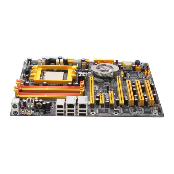
Page 31: Chapter 2 - Hardware Installation
Hardware Installation Chapter 2 - Hardware Installation System Board Layout... -
Page 32: System Memory
Hardware Installation Warning: Electrostatic discharge (ESD) can damage your system board, processor, disk drives, add-in boards, and other components. Perform the upgrade instruction procedures described at an ESD workstation only. If such a station is not available, you can provide some ESD protection by wearing an antistatic wrist strap and attaching it to a metal part of the system chassis. -
Page 33: Hardware Installation
Hardware Installation The system board supports the following memory interface. Single Channel (SC) Data will be accessed in chunks of 64 bits (8B) from the memory channels. Dual Channel (DC) Data will be accessed in chunks of 128 bits from the memory channels. - Page 34 Hardware Installation The integrated memory controller in AMD's 64-bit Socket 939 series CPU will directly catch data transmission from DDR RAM without passing through the Northbridge. Therefore when using 4 identical double side DIMMs or using 2 DIMMs in non-dual channels, the memory speed will reduce to DDR333.
- Page 35 Hardware Installation Frequent Q&A on Memory Usage Q: How can I obtain good performance on an overclocked system? A: Insert two identical broad bandwidth memories in DIMM 2 and DIMM 4. Q: Why will the system board fail to boot when 3 DIMMs are used? A: The integrated memory controller in AMD's 64-bit Socket 939 series CPU supports dual channel however the controller is not...
-
Page 36: Installing The Dim Module
Hardware Installation Installing the DIM Module A DIM module simply snaps into a DIMM socket on the system board. Pin 1 of the DIM module must correspond with Pin 1 of the socket. Notch Pin 1 1. Pull the “tabs” which are at the ends of the socket to the side. 2. -
Page 37: Cpu
Hardware Installation Overview The system board is equipped with a surface mount 939-pin CPU socket. This socket is exclusively designed for installing an AMD CPU. Installing the CPU 1. Make sure the PC and all other peripheral devices connected to it has been powered down. - Page 38 Hardware Installation 4. Unlock the socket by pushing the lever sideways, away from the socket, then lifting it up to a 90 angle. Make sure the lever is lifted to at least this angle otherwise the CPU will not fit in properly. Lever 5.
- Page 39 Hardware Installation 6. Insert the CPU into the socket until it is seated in place. The CPU will fit in only one orientation and can easily be inserted without exerting any force. Important: Do not force the CPU into the socket. Forcing the CPU into the socket may bend the pins and damage the CPU.
- Page 40 Hardware Installation Installing the Fan and Heat Sink The CPU must be kept cool by using a CPU fan with heat sink. Without sufficient air circulation across the CPU and heat sink, the CPU will overheat damaging both the CPU and system board. Note: •...
- Page 41 Hardware Installation 3. Place the heat sink on top of the CPU. Now hook one side of the retention clip onto the retention module base by fitting the holes on the retention clip into the retaining tabs of the retention module base.
- Page 42 Hardware Installation 4. Hook the other side of the retention clip (the one near the retention lever) so that the holes on the retention clip also fit into the retaining tabs of the retention module base. Note: You will not be able to secure the fan and heat sink assembly in place if it did not fit properly onto the retention module base.
-
Page 43: Jumper Settings
Hardware Installation Jumper Settings Clear CMOS Data 1-2 On: Normal 2-3 On: (default) Clear CMOS Data If you encounter the following, a) CMOS data becomes corrupted. b) You forgot the supervisor or user password. c) You are unable to boot-up the computer system because the processor’s ratio/clock was incorrectly set in the BIOS. - Page 44 Hardware Installation 4. After powering-on the system, press <Del> to enter the main menu of the BIOS. 5. Select the Genie BIOS Setting submenu and press <Enter>. 6. Set the processor’s clock/ratio to its default setting or an appro- priate setting. Refer to the Genie BIOS Setting section in chapter 3 for more information.
- Page 45 Hardware Installation PS/2 Power Select 1-2 On: 5V 2-3 On: 5VSB (default) JP7 is used to select the power of the PS/2 keyboard/mouse port. Selecting 5VSB will allow you to use the PS/2 keyboard or PS/2 mouse to wake up the system. BIOS Setting Configure the PS/2 keyboard/mouse wake up function in the Integrated Peripherals submenu of the BIOS.
-
Page 46: Usb Power Select
Hardware Installation USB Power Select USB 1-6 (JP5) 1-2 On: 5V 2-3 On: 5VSB (default) USB 7-10 (JP6) 1-2 On: 5V 2-3 On: 5VSB (default) JP5 and JP6 are used to select the power of the USB ports. Selecting 5VSB will allow you to use the USB keyboard or USB mouse to wake up the system.. - Page 47 Hardware Installation Speaker On/Off Select Buzzer 2-3 On: 1-2 On: Speaker On Speaker Off (default) The system board is equipped with a buzzer which serves as the PC’s speaker. By default the buzzer is “on” allowing you to hear the system’s beep messages and warnings.
- Page 48 Hardware Installation S/PDIF-out Settings JP52 1-2 On: 2-3 On: S/PDIF-out via S/PDIF-out via ALC850 nForce4 SLI JP52 is used to select the controller that will send signal to the S/PDIF-out port.
- Page 49 Hardware Installation Safe Boot 1-2 On: 2-3 On: Default Safe boot JP1 is used to safely reboot the system whenever the system hangs and you are unable to restart the system. 1. Power-off the system and unplug the power cord. 2.
-
Page 50: Rear Panel I/O Ports
Hardware Installation Rear Panel I/O Ports Front R/L (Line-out) PS/2 Line-in Mic-in LAN 1 LAN 2 Mouse 1394_1 S/PDIF-in PS/2 USB 1-2 USB 3-4 USB 5-6 S/PDIF-out Rear R/L Center/ Side R/L Subwoofer Karajan audio module The rear panel I/O ports consist of the following: •... - Page 51 Hardware Installation PS/2 Mouse and PS/2 Keyboard Ports PS/2 Mouse PS/2 Keyboard The system board is equipped with an onboard PS/2 mouse (Green) and PS/2 keyboard (Purple) ports - both at location CN2 of the system board. The PS/2 mouse port uses IRQ12. If a mouse is not connected to this port, the system will reserve IRQ12 for other expansion cards.
- Page 52 Hardware Installation S/PDIF-in/out Jacks S/PDIF-in S/PDIF-out SPDIF out SPDIF in The system board is equipped with an onboard S/PDIF-in RCA jack (red) and a S/PDIF-out RCA jack (yellow) at locations CN5 and CN7 respectively. The S/PDIF connector at location J3 is used to connect to optical S/PDIF ports.
- Page 53 Hardware Installation Karajan Audio Module Line-in Mic-in Front R/L (Line-out) Rear R/L Side R/L Center/ Subwoofer Karajan audio module Karajan audio connector Installing the Karajan Audio Module The system board comes with the Karajan audio module already installed on the board. The module is stabilized by means of the module holder.
- Page 54 Hardware Installation To install: 1. Fit the module holder onto the Karajan audio module. 2. Align the module’s plugs above the mounting holes then insert the plugs from the top through to the bottom of the system board. While at it, the 14-pin connector at the solder side of the module must also insert into the Karajan audio connector at location J7 of the system board.
- Page 55 Hardware Installation Mounting holes Karajan audio connector (J7) Karajan Audio Jacks • Line-in (Light Blue) This jack is used to connect any audio devices such as Hi-fi set, CD player, tape player, AM/FM radio tuner, synthesizer, etc. • Front Right/Left Jack - Line-out (Lime) This jack is used to connect to the front right and front left speakers of the audio system.
- Page 56 Hardware Installation Front Audio The front audio connector (J4) on the Karajan audio module allows you to connect to the line-out and mic-in jacks that are at the front panel of your system. Using this connector will disable the rear au- dio’s line-out and mic-in functions.
- Page 57 Hardware Installation IEEE 1394 1394_1 1394_2 The system board is equipped with an onboard IEEE 1394 port at location CN3 (IEEE 1394_1) of the system board. It is also equipped with an IEEE 1394 connector at location J8 (1394_2) for connecting an additional 1394 device. The 1394 port may come mounted on a card-edge bracket.
-
Page 58: Universal Serial Bus Ports
Hardware Installation Universal Serial Bus Ports USB 2 USB 1 USB 4 USB 3 USB 6 USB 5 USB 7-8 USB 9-10 The system board supports 10 USB 2.0/1.1 ports. USB allows data exchange between your computer and a wide range of simultaneously accessible external Plug and Play peripherals. - Page 59 Hardware Installation Driver Installation You may need to install the proper drivers in your operating system to use the USB device. Refer to your operating system’s manual or documentation for more information. Refer to chapter 4 for more information about installing the USB 2.0 driver.
-
Page 60: Rj45 Lan Port
Hardware Installation RJ45 LAN Port LAN 1 LAN 2 LAN 1 which is controlled by the Vitesse VSC8201 Gigabit Phy chip is at location CN4 and LAN 2 which is controlled by the Marvell 88E8001 Gigabit PCI chip is at location CN6. LAN allows the system board to connect to a local area network by means of a network hub. -
Page 61: Internal I/O Connectors
Hardware Installation I/O Connectors CD-in Internal Audio Connector Ground Ground Left audio Right audio channel channel Audio codec Line-in Front R/L Mic-in Center/Subwoofer Rear R/L Side R/L The CD-in (J2) connector on the Karajan audio module used to receive audio from a CD-ROM drive, TV tuner or MPEG card. -
Page 62: Floppy Disk Drive Connector
Hardware Installation Floppy Disk Drive Connector The system board is equipped with a 90 floppy disk drive connector that supports two standard floppy disk drives. To prevent improper floppy cable installation, the floppy disk header has a keying mechanism. The 34-pin connector on the floppy cable can be placed into the header only if pin 1 of the connector is aligned with pin 1 of the header. -
Page 63: Serial Ata Connectors
Hardware Installation Serial ATA Connectors Four Serial ATA ports supported by the nForce4 SLI chip (LANPARTY UT NF4 SLI-DR/D Venus) SATA 3 SATA 4 (J11) (J13) SATA 1 SATA 2 (J2) (J10) • SATA speed up to 3Gb/s • RAID 0, RAID 1, RAID 0+1 and JBOD •... - Page 64 Hardware Installation Four Serial ATA ports supported by the Silicon Image Sil 3114 chip (LANPARTY UT NF4 SLI-DR Venus only) SATA 6 (J29) SATA 5 (J28) 7 SATA 8 (J27) SATA 7 (J26) • SATA speed up to 1.5Gb/s • RAID 0, RAID 1, RAID 0+1 and RAID 5 Connecting Serial ATA Cables Connect one end of the Serial ATA cable to the Serial ATA...
-
Page 65: Ide Disk Drive Connector
Hardware Installation IDE Disk Drive Connector IDE 2 IDE 1 • NVIDIA RAID allows RAID arrays spanning across Serial ATA and Parallel ATA • RAID 0, RAID 1, RAID 0+1 and JBOD The system board is equipped with two shrouded PCI IDE headers that will interface four Enhanced IDE (Integrated Drive Electronics) disk drives. - Page 66 Hardware Installation If you are adding a third or fourth IDE device, use another IDE cable and install one end of the cable into the IDE 2 header (J22) on the system board and the other connectors to the IDE devices. Note: Refer to your disk drive user’s manual for information about selecting proper drive switch settings.
- Page 67 Hardware Installation Serial (COM) Port The system board is equipped with a 9-pin connector for connecting an external serial port. The serial port cable is an optional item and must be purchased separately. Insert the connector that is attached to the serial por t cable to the 9-pin connector (J4) then install the serial port bracket to an available bracket slot at the rear of the system chassis.
-
Page 68: Irda Connector
Hardware Installation IrDA Connector IRRX Ground N. C. IRTX Connect the cable connector from your IrDA module to the IrDA connector (J5). Note: The sequence of the pin functions on some IrDA cable may be reversed from the pin function defined on the system board. Make sure to connect the cable connector to the IrDA connector according to their pin functions. -
Page 69: Cooling Fan Connectors
Hardware Installation Cooling Fan Connectors Sense Sense Power Power Ground Ground Fan 2 CPU fan Ground Power Sense Fan 3 Fan 4 Fan 5 Ground N. C. N. C. Ground Power Power Connect the CPU fan’s cable connector to the CPU fan connector (J31) on the system board. - Page 70 Hardware Installation LEDs DRAM Power LED Standby Power LED Diagnostic LEDs DRAM Power LED This LED will light when the system’s power is on. Standby Power LED This LED will light when the system is in the standby mode. Diagnostic LEDs LED 2 to LED 5 are diagnostic LEDs.
-
Page 71: Power Connectors
Hardware Installation Power Connectors Use a power supply that complies with the ATX12V Power Supply Design Guide Version 1.1. An ATX12V power supply unit has a standard 24-pin ATX main power connector that must be inserted onto CN10. 1 2 2 4 +3.3VDC +12VDC +5VDC... - Page 72 Hardware Installation The FDD-type power connector is an additional power connector. If you are using two graphics cards, we recommend that you plug a power cable from your power supply unit onto the 5V/12V power connector at location J1. This will provide more stability to the entire system.
- Page 73 Hardware Installation Power Supply Requirements This section contains information about the minimum power required which were calculated based on the following basic peripheral configuration. • One hard drive • Two optical drives • One floppy drive • One sound card •...
- Page 74 Hardware Installation For Single PCI Express x16 Graphics Card ATX 12V 2.0 compliant - with a 24-pin ATX main power connector, dual 12V rails (12V and 12V ). Your power supply unit may come with an 8-pin EPS server style 12V power connector or 4-pin +12V power connector.
- Page 75 Hardware Installation Restarting the PC Normally, you can power-off the PC by: 1. Pressing the power button at the front panel of the chassis. 2. Pressing the power switch that is on the system board (note: not all system boards come with this switch). If for some reasons you need to totally cut off the power supplied to the PC, switch off the power supply or unplug the power cord.
-
Page 76: Front Panel Connectors
Hardware Installation Front Panel Connectors RESET SPEAKER HD-LED PWR-LED ATX-SW HD-LED: Primary/Secondary IDE LED This LED will light when the hard drive is being accessed. RESET: Reset Switch This switch allows you to reboot without having to power off the system thus prolonging the life of the power supply or system. - Page 77 Hardware Installation PWR-LED: Power/Standby LED When the system’s power is on, this LED will light. When the system is in the S1 (POS - Power On Suspend) or S3 (STR - Suspend To RAM) state, it will blink every second. Note: If a system did not boot-up and the Power/Standby LED did not light after it was powered-on, it may indicate that the CPU...
- Page 78 Hardware Installation EZ Touch Switches Reset Switch Power Switch The presence of the power switch and reset switch on the system board are user-friendly especially to DIY users. They provide convenience in powering on and/or resetting the system while fine tuning the system board before it is installed into the system chassis.
- Page 79 Hardware Installation PCI Express Slots PCI Express x16 PCI Express x1 PCI Express x4 PCI Express x16 Install PCI Express x16 graphics card, that comply to the PCI Express specifications, into the PCI Express x16 slot. To install a graphics card into the x16 slot, align the graphics card above the slot then press it down firmly until it is completely seated in the slot.
- Page 80 Hardware Installation Battery Battery The lithium ion battery powers the real-time clock and CMOS memory. It is an auxiliary source of power when the main power is shut off. Safety Measures • Danger of explosion if battery incorrectly replaced. • Replace only with the same or equivalent type recommend by the manufacturer.
-
Page 81: Sli Technology
Hardware Installation SLI Technology ® The NVIDIA (Scalable Link Interface) technology connects two identical SLI-ready PCI Express x16 graphics cards in a single and scalable system. Using the SLI bridge to connect two identical graphics cards will provide extreme performance allowing you to enjoy games with the most visual effects and the most graphics demanding multimedia utilities. - Page 82 Hardware Installation The PCI Express Slots SLI Mode The illustration below shows the bandwidth of the PCI Express slots when in SLI mode. Bandwidth x16 PCI Express slot x1 PCI Express slot N. C. x4 PCI Express slot x16 PCI Express slot...
- Page 83 Hardware Installation Single VGA Mode The illustration below shows the bandwidth of the PCI Express slots when in Single VGA mode. Bandwidth x16 PCI Express slot x1 PCI Express slot x4 PCI Express slot x16 PCI Express slot...
- Page 84 Hardware Installation Installing the Graphics Cards Important: Use two identical NVIDIA SLI-ready PCI Express x16 graphics cards. 1. Power-off the system and monitor then unplug the power cord. 2. Remove the screw of the bracket that is opposite the PCIE1 slot then remove the bracket.
- Page 85 Hardware Installation 4. Secure the graphics card with the screw you removed in step 2. 5. Remove the screw of the bracket that is opposite the PCIE4 slot then remove the bracket. PCIE4 6. Align the graphics card above the PCIE4 slot then press it down firmly until it is completely seated in the slot.
- Page 86 Hardware Installation 8. The distinctive feature of an SLI-ready graphics card is the presence of the SLI connector (goldfingers) on the card. 9. Align the SLI bridge (included in the system board package) above the SLI connector of the graphics cards then insert the bridge until it is properly seated in place.
- Page 87 Hardware Installation 10. Connect a 4-pin FDD-type power cable from the power supply unit to the 5V/12V power connector that is on the system board. 5V/12V power connector 11. Power-on the monitor first then restart the system so that Windows can detect the new hardware settings.
-
Page 88: Chapter 3 - Bios Setup
BIOS Setup Chapter 3 - BIOS Setup Award BIOS Setup Utility The Basic Input/Output System (BIOS) is a program that takes care of the basic level of communication between the processor and peripherals. In addition, the BIOS also contains codes for various advanced features found in this system board. -
Page 89: Bios Setup
BIOS Setup Standard CMOS Features Use the arrow keys to highlight “Standard CMOS Features” and press <Enter>. A screen similar to the one below will appear. The settings on the screen are for reference only. Your version may not be identical to this one. Date The date format is <day>, <month>, <date>, <year>. - Page 90 BIOS Setup Primary IDE Master, Primary IDE Slave, Secondary IDE Master and Secondary IDE Slave Move the cursor to a field then press <Enter>. The following screen will appear. The settings on the screen are for reference only. Your version may not be identical to this one.
- Page 91 BIOS Setup IDE HDD Auto-Detection Detects the parameters of the drive. The parameters will automati- cally be shown on the screen. Primary IDE Master/Slave and Secondary IDE Master/Slave The drive type information should be included in the documentation from your hard disk vendor. If you select ”Auto”, the BIOS will auto- detect the HDD &...
- Page 92 BIOS Setup Sector This field displays the number sectors per track. Drive A and Drive B These fields identify the types of floppy disk drives installed. None No floppy drive is installed 360K, 5.25 in. 5-1/4 in. standard drive; 360KB capacity 1.2M, 5.25 in.
- Page 93 BIOS Setup Extended Memory Displays the amount of extended memory detected during boot-up. Total Memory Displays the total memory available in the system.
-
Page 94: Advanced Bios Features
BIOS Setup Advanced BIOS Features The Advanced BIOS Features allows you to configure your system for basic operation. Some entries are defaults required by the system board, while others, if enabled, will improve the performance of your system or let you set some features according to your preference. The screen above list all the fields available in the Advanced BIOS Features submenu, for ease of reference in this manual. - Page 95 BIOS Setup Removable Device Priority This field is used to select the boot sequence of the removable devices. Move the cursor to this field then press <Enter>. Use the Up or Down arrow keys to select a device then press <+> to move it up or <->...
- Page 96 BIOS Setup Hard Disk Boot Priority This field is used to select the boot sequence of the hard drives. Move the cursor to this field then press <Enter>. Use the Up or Down arrow keys to select a device then press <+> to move it up or <->...
- Page 97 BIOS Setup Network Boot Priority This field is used to select the boot sequence of the network. Move the cursor to this field then press <Enter>. Use the Up or Down arrow keys to select a device then press <+> to move it up or <- >...
- Page 98 BIOS Setup First Boot Device, Second Boot Device, Third Boot Device and Boot Other Device Select the drive to boot first, second and third in the “First Boot Device” “Second Boot Device” and “Third Boot Device” fields respectively. The BIOS will boot the operating system according to the sequence of the drive selected.
- Page 99 BIOS Setup Typematic Rate Setting Disabled Continually holding down a key on your keyboard will cause the BIOS to report that the key is down. Enabled The BIOS will not only report that the key is down, but will first wait for a moment, and, if the key is still down, it will begin to report that the key has been depressed repeatedly.
- Page 100 BIOS Setup MPS Version Control for OS This field is used to select the MPS version that the system board is using. OS Select for DRAM > 64MB Select the “OS2” option only if the system that is running an OS/2 operating system has greater than 64MB RAM.
-
Page 101: Advanced Chipset Features
BIOS Setup Advanced Chipset Features The settings on the screen are for reference only. Your version may not be identical to this one. This section gives you functions to configure the system based on the specific features of the chipset. The chipset manages bus speeds and access to system memory resources. - Page 102 BIOS Setup CPU Thermal-Throttling Thermal throttling regulates the thermal environment by alternating between running the processor at full speed and placing the processor in a sleep state whenever the upper limits of the thermal envelop are reached. System BIOS Cacheable When this field is enabled, accesses to the system BIOS ROM addressed at F0000H-FFFFFH are cached, provided that the cache controller is enabled.
-
Page 103: Integrated Peripherals
BIOS Setup Integrated Peripherals The screen above list all the fields available in the Integrated Peripherals submenu, for ease of reference in this manual. In the actual CMOS setup, you have to use the scroll bar to view the fields. The settings on the screen are for reference only. - Page 104 BIOS Setup OnChip IDE Channel0 and OnChip IDE Channel1 These fields allow you to enable or disable the primary and second- ary IDE controller. The default is Enabled. Select Disabled if you want to add a different hard drive controller. Primary Master/Slave PIO and Secondary Master/Slave PIO PIO means Programmed Input/Output.
- Page 105 BIOS Setup Serial-ATA 2 This field is used to enable or disable the second channel (SATA 3 and SATA 4) of the Serial ATA supported by the NVIDIA nForce4 SLI chipset. IDE Prefetch Mode This allows data and addresses to be stored in the internal buffer of the chip, thus reducing access time.
- Page 106 BIOS Setup RAID Enable This field is used to enable or disable the RAID function of Parallel ATA drives and Serial ATA drives (drives connected to SATA 1 to SATA 4). IDE Primary Master RAID and IDE Primary Slave RAID These fields are used to enable or disable the RAID function of primary IDE’s master and slave channels.
- Page 107 BIOS Setup AC97 Audio Auto Select this option when using the onboard audio. Disabled Select this option when using a PCI sound card. Power On By Button Set this field to Enabled if you are using the power button to power-on the system.
- Page 108 BIOS Setup KB Power On Password Move the cursor to this field and press <Enter>. Enter your pass- word. You can enter up to 5 characters. Type in exactly the same password to confirm, then press <Enter>. The power button will not function once a keyboard password has been set in this field.
-
Page 109: Power Management Setup
BIOS Setup Power Management Setup The Power Management Setup allows you to configure your system to most effectively save energy. The settings on the screen are for reference only. Your version may not be identical to this one. ACPI Function This function should be enabled only in operating systems that ®... - Page 110 BIOS Setup Power Management This field allows you to select the type (or degree) of power saving by changing the length of idle time that elapses before the “HDD Power Down” field is activated. Min Saving Minimum power saving time for the “HDD Power Down”...
- Page 111 BIOS Setup HDD Down In Suspend The default setting is Disabled. When enabled, the hard drive will be powered off once the system enters the Suspend mode. Soft-Off by PBTN This field allows you to select the method of powering off your system.
- Page 112 BIOS Setup Power-On By Alarm Enabled When Enabled, you can set the time you would like the Soft Power Down (Soft-Off) PC to power-on in the “Time (dd:hh:mm) of Alarm” field. However, if the system is being accessed by incoming calls or the net- work prior to the time set in the field, the system will give priority to the incoming calls or network.
- Page 113 BIOS Setup PnP/PCI Configurations This section describes configuring the PCI bus system. It covers some very technical items and it is strongly recommended that only experienced users should make any changes to the default settings. The settings on the screen are for reference only. Your version may not be identical to this one.
- Page 114 BIOS Setup Resources Controlled By The Award Plug and Play BIOS has the capability to automatically configure all of the boot and Plug and Play compatible devices. Auto(ESCD) The system will automatically detect the settings for you. Manual Choose the specific IRQ in the “IRQ Resources” field.
-
Page 115: Pc Health Status
BIOS Setup PC Health Status The settings on the screen are for reference only. Your version may not be identical to this one. Shutdown Temperature You can prevent the system from overheating by selecting a tem- perature in this field. If the system detected that its temperature exceeded the one set in this field, it will automatically shutdown. - Page 116 BIOS Setup On If CPUTemp” field to allow the CPU fan to rotate full speed at the selected lower temperature. Fan 2 Fully On If PWMTemp This field is used to select the system temperature that would allow Fan 2 to rotate at full speed. Fan 2 Turn Off If PWMTemp This field is used to select the system temperature that would allow Fan 2 to rotate at a start speed which is the slowest speed.
-
Page 117: Genie Bios Setting
BIOS Setup Genie BIOS Setting The settings on the screen are for reference only. Your version may not be identical to this one. DRAM Configuration Move the cursor to this field and press <Enter>. The following screen will appear. The settings on the screen are for reference only. Your version may not be identical to this one. - Page 118 BIOS Setup DRAM Frequency Set (Mhz) This field is used to set a memory clock limit on the system. This will prevent the memory speed from running faster than this frequency. Command Per Clock (CPC) This field is used to enable the DRAM commands and address that will be driven for 2 clock cycles and select the second phase of the 2 clock command and address.
- Page 119 BIOS Setup Row Refresh Cyc Time (Trfc) This field is used to select the row refresh cycle time. Auto refresh active to RAS# active or RAS# to auto refresh - similar to Trc. Row to Row Delay (Trrd) This field is used to select the row to row delay time of different banks.
- Page 120 BIOS Setup DRAM Drive Strength This field is used to select a level of the DRAM drive strength. Max Async Latency This field is used to select the DRAM maximum asynchronous latency time. Read Preamble Time This field is used to select the time prior to the max-read DOS return when the DOS receiver is turned on.
- Page 121 BIOS Setup FSB Bus Frequency This field provides several options for selecting the FSB of the CPU. The available options allow you to adjust the CPU’s bus clock by 1MHz increment. Important: Selecting a bus frequency other than the default setting may result to the CPU’s or system’s instability and are not guaranteed to provide better system performance.
- Page 122 BIOS Setup CPU Core Voltage This field will show the CPU’s current voltage. LDT Bus Voltage This field will show the LDT bus voltage. Chipset Voltage This field will show the chipset’s current voltage. DRAM 2.5V Voltage This field will show the DRAM’s current voltage. CPU VID Control This field allows you to manually adjust to a higher core voltage that is supplied to the CPU.
- Page 123 BIOS Setup DRAM Voltage Control This field allows you to manually select higher voltage supplied to the DRAM. If you want to use the DRAM’s default voltage, leave this field in its default setting. Important: Although this function is supported, we do not recommend that you use a higher voltage because unstable current may be supplied to the system board causing damage.
-
Page 124: Cmos Reloaded
BIOS Setup CMOS Reloaded The CMOS Reloaded submenu allows you to save different configu- rations and when needed, allows you to conveniently restore one of these previously saved configurations. Highlight CMOS Reloaded in the main menu then press <Enter>. The screen above list all the fields available in the CMOS Reloaded submenu, for ease of reference in this manual. - Page 125 BIOS Setup Auto Save Bootable Setting This field is used to automatically save the last bootable setting from CMOS to an area in the SEEPROM referred to as the backup bank. To use this function: 1. Set this field to Enabled. 2.
- Page 126 BIOS Setup Saving, Loading and Naming BIOS Settings For overclockers who require different sets of settings for various system environments or operating systems, CMOS Reloaded allows you to save, load and name up to four sets of BIOS settings - in the “User Defined Setting Bank #1”...
- Page 127 BIOS Setup Load from this Bank To load the setting saved in the bank, move the cursor to “Load from this Bank” then press <Enter>. The setting in this bank will replace the current setting. Make sure to save before you exit the BIOS setup utility by selecting “Y”...
-
Page 128: Load Optimized Defaults
BIOS Setup Load Optimized Defaults The “Load Optimized Defaults” option loads optimized settings from the BIOS ROM. Use the default values as standard values for your system. Highlight this option in the main menu and press <Enter>. Type <Y> and press <Enter> to load the Setup default values. -
Page 129: Set Supervisor Password
BIOS Setup Set Supervisor Password If you want to protect your system and setup from unauthorized entry, set a supervisor’s password with the “System” option selected in the Advanced BIOS Features. If you want to protect access to setup only, but not your system, set a supervisor’s password with the “Setup”... -
Page 130: Set User Password
BIOS Setup Set User Password If you want another user to have access only to your system but not to setup, set a user’s password with the “System” option se- lected in the Advanced BIOS Features. If you want a user to enter a password when trying to access setup, set a user’s password with the “Setup”... - Page 131 BIOS Setup Save & Exit Setup When all the changes have been made, highlight “Save & Exit Setup” and press <Enter>. Type “Y” and press <Enter>. The modifications you have made will be written into the CMOS memory, and the system will reboot. You will once again see the initial diagnostics on the screen.
-
Page 132: Exit Without Saving
BIOS Setup Exit Without Saving When you do not want to save the changes you have made, highlight “Exit Without Saving” and press <Enter>. Type “Y” and press <Enter>. The system will reboot and you will once again see the initial diagnostics on the screen. If you wish to make any changes to the setup, press <Ctrl>... -
Page 133: Nvraid Bios
BIOS Setup NVRAID BIOS The NVRAID BIOS utility, supported by the NVIDIA nForce4 SLI chipset, is used to configure and manage RAID on Serial ATA drives (SATA 1 to SATA 4) and Parallel ATA drives. After you power up the system and all drives have been detected, the NVRAID BIOS status message screen will appear. -
Page 134: Updating The Bios
Updating the BIOS To update the BIOS, you will need the new BIOS file and a flash utility, AWDFLASH.EXE. You can download them from DFI’s web site or contact technical support or your sales representative. 1. Save the new BIOS file along with the flash utility AWDFLASH.EXE to a floppy disk. - Page 135 BIOS Setup 6. The following will appear. Do You Want to Save BIOS (Y/N) This question refers to the current existing BIOS in your system. We recommend that you save the current BIOS and its flash utility; just in case you need to reinstall the BIOS. To save the current BIOS, press <Y>...
-
Page 136: Chapter 4 - Supported Softwares
Supported Software Chapter 4 - Supported Software Drivers, Utilities and Software Applications The CD that came with the system board contains drivers, utilities and software applications required to enhance the performance of the system board. Inser t the CD into a CD-ROM drive. The autorun screen (Mainboard Utility CD) will appear. -
Page 137: Supported Software
Supported Software Microsoft DirectX 9 To install, please follow the steps below. 1. On the left side of the autorun screen, click the “TOOLS” icon. 2. Click “Microsoft DirectX 9” on the main menu. The following screen will appear. 3. Click “I accept the agreement” then click “Next”. 4. - Page 138 Supported Software NVIDIA Windows nForce Drivers The NVIDIA Windows nForce Drivers contains the following. • NVIDIA SMBus Driver • NVIDIA Ethernet Driver • NVIDIA IDE Driver • NVIDIA Audio Driver To install NVIDIA Windows nForce Drivers, please follow the steps below.
- Page 139 Supported Software 3. The following screen will appear. Select the drivers you want to install. The drivers will be installed automatically. Make sure you have selected “NVIDIA IDE Driver” because this driver will replace Windows ATA drivers enabling the processor and other system level hardware to be more productive and efficient.
- Page 140 Supported Software 5. When prompted about installing NVIDIA Firewall and ForceWare Network Access Manager, click “Yes”. 6. Click “Next” to install NVIDIA Firewall and ForceWare Network Access Manager.
- Page 141 Supported Software 7. Select the type of setup you prefer then click “Next”. 8. Click “Yes” to activate Firewall.
- Page 142 Supported Software 9. Click “Finish” to exit setup. NVIDIA ForceWare Network Access Manager After completing installation, the “NVIDIA web-based...” icon is automatically created on your desktop. Double-click this icon to launch the NVIDIA ForceWare Network Access Manager utility. The utility allows you to configure the Ethernet interface features and personal Firewall for optimized security.
- Page 143 Supported Software nTune NVIDIA nTune is an easy monitoring application that allows tuning of gaming performance, setting the system to quiet operation when playing DVD and monitoring the system functions. nTune is the safest way to change the bus speeds, memory timings and adjust voltages. Click “Benchmark and automatically tune my system”...
- Page 144 Supported Software Click “NView” to configure desktop management. Click “NVMixer” for audio tuning.
-
Page 145: Installation Notes
2. All steps or procedures to install software drivers are subject to change without notice as the softwares are occassionally updated. Please go to DFI's web site at "http://www.dfi.com/support1/ download2.asp" for the latest version of the drivers or software applications. -
Page 146: Chapter 5 - Cool'n'quiet Technology
Cool‘n’Quiet Technology Chapter 5 - Cool’n’Quiet Technology Cool‘n’Quiet Technology The AMD Cool‘n’Quiet technology allows the system to detect the CPU’s tasks and utilization status. When the CPU’s task slows down, the system effectively lowers power consumption by lowering its CPU speed and voltage, subsequently decreasing its noise level. To enable the Cool‘n’Quiet technology, the following settings are required. - Page 147 Cool‘n’Quiet Technology 4. Press <Esc> to return to the main menu of the BIOS setup utility. Select “Save & Exit Setup” and press <Enter>. 5. Type <Y> and press <Enter>. 6. Reboot the system. Step 2: Install the Cool‘n’Quiet Driver AMD’s website provides free download of the Cool‘n’Quiet driver.
- Page 148 Cool‘n’Quiet Technology Step 3: Configure Power Management in Windows 1. On the Windows desktop, click Start then select Control Panel. 2. In Control Panel, double-click the Power Options icon. 3. In the Power Schemes tab, select Minimal Power Management under the Power schemes section then click OK.
-
Page 149: Chapter 6 - Raid
RAID Chapter 6 - RAID The NVIDIA nForce4 SLI chip supports NVIDIA RAID (Redundant Array of Independent Disk) that allows RAID arrays spanning across 4 Serial ATA and Parallel ATA drives. It supports RAID 0, RAID 1, RAID 0+1 and JBOD. The Silicon Image Sil 3114 chip (LANPARTY UT NF4 SLI-DR Venus only) allows configuring RAID on another 4 Serial ATA por ts. - Page 150 RAID RAID 5 RAID 5 stripes data and parity information across hard drives. It is fault tolerant and provides better hard drive performance and more storage capacity. JBOD (Spanning) JBOD redundantly stores the same data on multiple disks that appear as a single disk on the operating system. Settings To enable the RAID function, the following settings are required.
- Page 151 RAID Important: Make sure you have installed the Serial/Parallel ATA drives and connected the data cables otherwise you won’t be able to enter the RAID BIOS utility. Step 2: Configure Serial/Parallel ATA in the Award BIOS Settings for Drives Supported by nForce4 SLI 1.
- Page 152 RAID Settings for Drives Supported by Silicon Image Sil 3114 1. Power-on the system then press <Del> to enter the main menu of the Award BIOS. 2. Select the Genie BIOS Setting submenu. 3. Set the “Sil3114 S-ATA RAID Control” field to “SATA RAID”. 4.
- Page 153 RAID Step 3: Configure RAID in the RAID BIOS Configure RAID in the NVRAID BIOS When the system powers-up and all drives have been detected, the NVRAID BIOS status message screen will appear. Press the <F10> key to enter the utility. The utility allows you to build a RAID system on Serial ATA drives and Parallel ATA drives.
- Page 154 RAID At this point you will be prompted to insert a floppy disk containing the RAID driver. Insert the provided RAID driver diskette. Locate for the drive where you inserted the diskette then select “NVIDIA nForce4 ATA Controller”. Press <Enter> to install the driver.
- Page 155 RAID ® Installing the Sil 3114 RAID Driver on Existing Windows XP or ® Windows 2000 1. Insert the provided CD into a CD-ROM drive. 2. On the left side of the autorun screen, click the “TOOLS” icon. 3. Click “Silicon Image RAID Drivers”. A “readme” screen which contains the RAID drivers installation instructions will appear.
-
Page 156: Appendix A - System Error Message
System Error Message Appendix A - System Error Message When the BIOS encounters an error that requires the user to correct something, either a beep code will sound or a message will be displayed in a box in the middle of the screen and the message, PRESS F1 TO CONTINUE, CTRL-ALT-ESC or DEL TO ENTER SETUP, will be shown in the information box at the bottom. - Page 157 System Error Message setting than indicated in Setup. Determine which setting is correct, either turn off the system and change the jumper or enter Setup and change the VIDEO selection. FLOPPY DISK(S) fail (80) Unable to reset floppy subsystem. FLOPPY DISK(S) fail (40) Floppy type mismatch.
-
Page 158: Appendix B - Troubleshooting
Troubleshooting Appendix B - Troubleshooting Troubleshooting Checklist This chapter of the manual is designed to help you with problems that you may encounter with your personal computer. To efficiently troubleshoot your system, treat each problem individually. This is to ensure an accurate diagnosis of the problem in case a problem has multiple causes. -
Page 159: Troubleshooting
Troubleshooting The picture seems to be constantly moving. 1. The monitor has lost its vertical sync. Adjust the monitor’s vertical sync. 2. Move away any objects, such as another monitor or fan, that may be creating a magnetic field around the display. 3. -
Page 160: Hard Drive
Troubleshooting Hard Drive Hard disk failure. 1. Make sure the correct drive type for the hard disk drive has been entered in the BIOS. 2. If the system is configured with two hard drives, make sure the bootable (first) hard drive is configured as Master and the sec- ond hard drive is configured as Slave. - Page 161 Troubleshooting 3. Verify that the attached serial device works by attaching it to a serial port that is working and configured correctly. If the serial device does not work, either the cable or the serial device has a problem. If the serial device works, the problem may be due to the onboard I/O or the address setting.