Advertisement
Quick Links
Handbook for the SXVF-H35
Issue 1 August 2007
Starlight Xpress Ltd
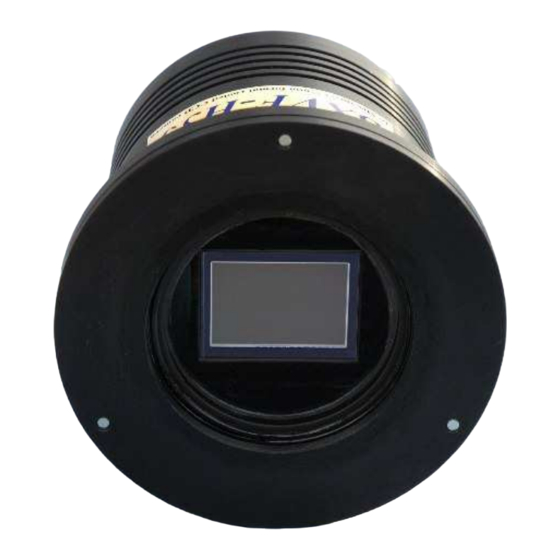
SXVF-H35
CCD camera user manual
Thank you for purchasing a Starlight Xpress CCD camera. We hope that you will be
very satisfied with its performance. The SXVF-H35 is a very large format, high-
resolution cooled CCD camera, especially designed for astronomical imaging. The
SXVF-H35 uses a Kodak KAI11002 Interline CCD, with 4008 x 2672 pixels in a
36.1mm x 24.05mm active area. The use of high performance microlenses on the
CCD surface gives the greatest possible throughput of light to the pixels and the
resulting QE is very good over the entire visible spectrum. Our new 'F' type USB2
interface hardware gives an exceptionally fast download speed of about 2 megapixels
per second, and so the SXVF-H35 can download a full resolution 16 bit image in only
8 seconds.
1
Advertisement

Related Manuals for Starlight Xpress SXVF-H35


Summary of Contents for Starlight Xpress SXVF-H35
- Page 1 QE is very good over the entire visible spectrum. Our new ‘F’ type USB2 interface hardware gives an exceptionally fast download speed of about 2 megapixels per second, and so the SXVF-H35 can download a full resolution 16 bit image in only 8 seconds.
- Page 2 1600 x 1200 pixels and 32 bit colour. A medium specification Pentium with between 1GHz and 3GHz processor speed is ideal. Please note that the SXVF-H35 is not designed for USB1.1 operation and will give inferior results if used on USB1.1.
- Page 3 Handbook for the SXVF-H35 Issue 1 August 2007 A rear view, showing the input and output connectors...
- Page 4 Handbook for the SXVF-H35 Issue 1 August 2007 Connect the miniature 4 way power plug to the socket on the rear of the camera and screw the retaining ring into place. The LED on the rear of the camera will light a dim yellow.
- Page 5 There are two simple options, one of which is available to everyone: 1) Attach a standard ‘M42’ SLR camera lens to the SXVF-H35, using the 27mm spacer/adaptor to achieve approximately the correct focal distance.
- Page 6 One potential problem with taking daylight images is the strong infrared response of the SXVF-H35 as this will cause ‘soft focus’ with camera lenses. Soft focus is much reduced by keeping the aperture setting below F8. Also, IR blocking filters are available from various suppliers (True Technology, Edmunds etc.) and are...
- Page 7 ‘crispness’. At this point, you will have a working knowledge of how to take and process an SXVF-H35 image. It is time to move on to astronomical imaging, which has its own, unique, set of problems!
- Page 8 F = Pixel size * 205920 / Resolution (in arc seconds) In the case of the SXVF-H35 and a 2 arc seconds per pixel resolution, we get F = 0.009 * 205920 / 2...
- Page 9 Handbook for the SXVF-H35 Issue 1 August 2007 Because of the large CCD size used in the H35, field vignetting and field curvature will be a problem with many general purpose telescopes. The larger SCTs and many of the new ‘APO’ refractors will not suffer so badly from this issue, but you may have to compromise on vignetting and usable field size when imaging with a less highly corrected instrument.
- Page 10 The SXVF-H35 generates relatively little dark signal and so dark frames are not essential for short exposures of less than a few minutes, but it is a good idea to record at least one for each exposure time used during an imaging session.
- Page 11 Handbook for the SXVF-H35 Issue 1 August 2007 Processing the deep-sky image: Below you will see typical examples of a dark frame and an uncalibrated raw image of M16. A typical 5 minute dark frame exposure. Note the random scatter of ‘warm pixels’...
- Page 12 Issue 1 August 2007 Warm pixels in a small portion of the raw image The isolated nature of the warm pixels in an SXVF-H35 image permits you to use several different methods of removing them from your raw images. Subtracting a dark frame is the most commonly used means of removing the warm pixels, but is not necessarily the best or most effective method.
- Page 13 Handbook for the SXVF-H35 Issue 1 August 2007 Warm pixels removed by the application of a 3x3 median filter A second option is to run a 3x3 ‘Median’ filter on the image. This simple method will remove isolated hot pixels and replace them with the median value of the pixels adjacent to them.
- Page 14 Handbook for the SXVF-H35 Issue 1 August 2007 is done by using a ‘statistical’ summing technique, such as median or sigma combining, then the warm pixels will be removed altogether. This method needs more powerful image processing than is available in SXV_Hmf, but both AstroArt and Maxim DL can do it.
- Page 15 Taking pictures of the Moon and planets: The SXVF-H35 is not intended for planetary imaging, as a much smaller CCD is in many ways much better for this. However, lunar imaging is a different matter and the H35 can give impressive whole-moon pictures.
- Page 16 Other features of SXV_H35 ‘Slew & Sum’ imaging: The SXVF-H35 can be used in an automatic image-stacking mode, called ‘Slew & Sum’. The camera is set to take several sequential exposures, which are automatically ‘slewed’ into alignment and then summed together by the software. This mode can help to overcome a poor RA drive by summing images that have exposure times shorter than the drive error period.
- Page 17 Handbook for the SXVF-H35 Issue 1 August 2007 To take an S&S image, go to the camera interface window and select an exposure time for one image of the sequence. Do not use a very short exposure time, as the read-out noise will become dominant.
- Page 18 5mA per output. This socket may be used for telescope control if the SXVF-H35 is employed as an autoguider, but is primarily intended to be the control output for the optional add-on autoguider camera head, available for use with the SXVF-H35.
- Page 19 If ‘active high’ inputs are needed, or a very low control voltage drop is essential, then you will need to add a Starlight Xpress ‘relay box’ between the guider output and the input to the mount. Please contact your local distributor if a relay box is required.
- Page 20 The autoguider installed on a 80mm refractor guide ‘scope in the author’s garden To use the autoguider, please proceed as follows: 1) Having started the SXVF-H35 software, open the autoguider control panel by clicking on the autoguider menu button. The autoguider control panel with a guide star selected...
- Page 21 Handbook for the SXVF-H35 Issue 1 August 2007 2) Press the ‘Start’ button and a series of 1 second exposure guider images will begin to appear in the picture frame. If the images look too dim, use the ‘Stretch Image’ slider to increase its contrast and brightness until the noise begins to be visible.
- Page 22 ********************************************************************* Camera maintenance: Very little maintenance is needed to keep the SXVF-H35 in excellent operating order, however two problems, which are common to all CCD equipment, are likely to show up on occasion. These are dust and condensation.
- Page 23 Handbook for the SXVF-H35 Issue 1 August 2007 2) Remove the two M3 screws from the camera back plate and ease the plate out of the camera body. You may need to press down with a finger on the USB socket while pulling up on the camera barrel to overcome the friction.
- Page 24 CCD field, this may indicate that the CCD plane needs to be adjusted. The front plate of the SXVF-H35 incorporates three sets of antagonistic screws that allow the plate to be tilted by up to about +/- 1 degree relative to the CCD surface.
- Page 25 Handbook for the SXVF-H35 Issue 1 August 2007 ********************************************************************* Some details of the camera and the CCD characteristics CCD type: Kodak KAI 11002 interline CCD imager. CCD size: Active area 36.3 x 24.2mm Pixel size: 9 x 9uM QE peak: approx.
-
Page 26: Conditions Of Guarantee
Issue 1 August 2007 Dear User, Thank you for purchasing a Starlight Xpress CCD Imaging System. We are confident that you will gain much satisfaction from this equipment, but please read carefully the accompanying instruction manual to ensure that you achieve the best performance that is capable of providing.