Article

Role of Power Converters in Inductive Power Transfer System for Public Transport—A Comprehensive Review

by
Sooraj Varikkottil
1,
Febin Daya John Lionel
2,*,
Mohan Krishna Srinivasan
3,*,
Sheldon Williamson
4,
Ramani Kannan
5,* and
Lila Iznita Izhar
5,*
1
Tata Elxsi, Trivandrum 695581, India
2
Electric Vehicles Incubation, Testing and Research Center, Vellore Institute of Technology, Chennai 600127, India
3
Department of Electrical and Electronics Engineering, Alliance College of Engineering and Design, Alliance University, Bangalore 562106, India
4
Department of Electrical, Computer and Software Engineering, Ontario Tech University, Oshawa, ON L1H 7K4, Canada
5
Department of Electrical and Electronics Engineering, Universiti Teknologi Petronas, Seri Iskandar 32610, Malaysia
*
Authors to whom correspondence should be addressed.
Symmetry 2022, 14(3), 508; https://doi.org/10.3390/sym14030508
Submission received: 22 January 2022 / Revised: 23 February 2022 / Accepted: 25 February 2022 / Published: 2 March 2022
(This article belongs to the Special Issue Symmetry with IoT in Electrical Engineering)

Abstract

:
IPT (inductive power transfer) charging is a highly flexible concept that allows for charging at any possible opportunity and is highly versatile for vehicles of all sizes. IPT wireless charging technology employs high-power inductive energy transfer between the components embedded into streets and the receiving equipment mounted below the vehicle. When the vehicle moves over the charging point, the contactless charging process is initiated between the components and the vehicle. In this work, the role of power converter topologies in IPT systems are studied for electric vehicle (EV) charging applications. Further, the predominant topologies are compared and analyzed in detail. The contingency in misalignment, loading and frequency shift are discussed for various converter topologies. The tolerance in misalignment poses serious challenges for wireless chargers in EVs. Therefore, there is currently a need to design a symmetric IPT system with multiple decoupled receiving coils. The significance of power inverter topologies for achieving resonance, as well as the generation of high-frequency supply, has been studied in detail. Experimental waveforms that are related to the explanations in this work are provided to substantiate the advantages regarding the converters.

1. Introduction

Over the last few decades, the wireless charging of electric vehicles (EV) has reverberated through global research [1,2,3]. The method is widely used for applications such as charging mobile phones, biomedical applications, charging electric vehicles, charging solar power satellites and powering aircrafts. The different techniques of wireless power transfer include inductive coupling, resonant inductive coupling capacitive coupling, magneto dynamic coupling, microwaves, and light waves [1,2,3]. Wireless charging of electric vehicles is achieved by a resonance enhanced inductive power transfer system [4,5,6]. This is applicable to near field misalignment, in particular [7,8]. However, the power transfer capability is high compared to the other wireless power transfer methods [9,10,11,12]. In 1894, Nikola Tesla used electro-dynamic induction to light the incandescent lamp at 35th South Fifth Avenue laboratory [13,14]. Tesla invented the Tesla coil (high voltage resonant transformer), patented in 1897. In 1970, the PATH program was initiated by UC Berkeley; it looked in depth at the inductive power transfer method [14]. An experimental roadway test track was built during 1990; they achieved a power transfer efficiency of 60%. The distance between the primary and the secondary coil was less than 10 cm in this case. Similarly, in 1993, Professor John Boys and Professor Grant Covic developed a system to transfer high-power in a large air gap at the University of Auckland [15,16]. In November 2006, Marin Soljacic and his team used strongly coupled resonators for wireless power transfer at the Massachusetts Institute of Technology. The research in this field has circumvented most of the significant research problems, such as power transfer efficiency and power flow management under the contingency in misalignment [17,18]. The system is comprised of the primary high-frequency inverter followed by an inductive airgap and secondary side converter [19,20]. The primary and secondary side inductive coils are separated by some distance comparable to the clearance of vehicle from ground to the chassis. A high-frequency AC supply is fed to the inductive track with the help of an inverter; the induced high-frequency voltages are rectified and filtered before connecting to the load [21,22]. Fundamentally, the inductive power transfer is based on a combination of Faraday and Ampere circuital law. Moreover, inductive power transfer without resonance is less efficient for larger air gaps.
There are certain advantages for the wireless charging systems over connected charging systems [23].
  • Autonomous—The wireless charging is autonomous. It will detect the vehicle automatically and charge.
  • Weatherproof protection—The coil is buried under the road surface and not exposed to the atmosphere.
  • Anti-vandalism—There is a much lower possibility of vandalizing the charging system.
Similarly, the areas in which more improvement in IPT systems is needed are enumerated below.
  • Foreign object detection—In case the foreign particle is present in between the coil, to optimize the power flow
  • Preliminary cost of implementation
  • Efficiency of the IPT system over connected charging
  • Power density of the IPT system
These are the areas in which significant improvement is needed. The power electronic converters play a vital role in improving the power transfer efficiency and high-power density. These areas are the focus of the paper. There are multiple challenges, such as EMC and environmental impact on the coil, to making IPT systems commercially viable.
Different standards and the specifications for different applications of IPT systems are mentioned in Table 1.
As per the guidelines of the International Commission on Non-Ionizing Radiation Protection (ICNIRP), the internal electric field limit is 1.35 × 10⁻⁴ f, where f is the frequency of the field, and the limit is 83 V/m [24]. The human tissue magnetic field is 27 µT (21.4 A/m) when the system operates at ICNIRP standards. The electro motive force (EMF) should meet with the IEEEC95.1-2345 standards. It was observed that nerve excitation is lower when the frequency is less than 100 kHz; then, the tissue will become heated further. This should be avoided in the case of an electric vehicle. In addition, the comparison of different wireless power transfer schemes has been explained in Table 2.
A meaningful arrangement of the energy storage elements, along with the semiconductor switches, has resulted in new possibilities in the IPT system [27,28,29]. The primary compensation of IPT systems reduces the VA rating; the secondary compensation is meant to improve the power transfer level [30]. However, the consistency in power transfer level can be maintained by adjusting the operating frequency during the contingency in misalignment. The power converter topologies and path impedance decide the shape, magnitude, position, and frequency of the primary power supply. Topologies such as LCL, SLC, CLC are very common in practice [31,32]. SLC-based resonance shows poor light load efficiency, but LCL is preferable over a wide range of loads [33,34]. Hence, each converter combination and topology play a significant role in the operation of IPT systems [35,36].
A block diagram representation of an IPT system is shown in Figure 1. The power drawn from the AC source is connected to the uncontrolled rectifier with a filter. The input power stage also acted as a power factor correction mechanism. The rectified DC power supply is fed to the high-frequency inverter, followed by resonance topology and inductive coil. The secondary pickup coil is connected to the resonance topology, followed by an uncontrolled bridge rectifier and filter before connecting to the load. The secondary side rectifier could be controlled, or uncontrolled, depending on the need of power flow control [37,38]. In some recent works, a boost converter is added before the load to improve the quality factor, as well as to control the power flow.
This generalized block diagram implicitly conveys the importance of the resonance in the circuit [39]. Hence, the resonance topology plays a significant role in IPT systems. Similarly, the order of resonance also adds more significance to it. Hence, study on the order and the arrangement of energy storage elements with the power semiconductor switches is essential and is, therefore, discussed in detail in this paper. Further, different types of power converter topologies, their different operating conditions and merits, are discussed in detail. In addition, contingency in misalignment, frequency of operation and load variations are also discussed for different power converter topologies [40,41,42,43]. In a near field power transfer, the inductive power transfer is the most efficient power transfer. The high-frequency magnetic flux lines can effectively link to the secondary coil if the coil is near and the resonance is present. The fundamental aspects that influence the power transfer have been reviewed in detail and have demonstrated the way in which they influence the performance of the IPT system [35,36]. The figure of merit of the IPT system is the product of the coupling coefficient and the quality factor.

2. Impact of Resonance Architectures

The resonance converter topology plays a vital role in the amount of power transfer and distance [44,45,46]. An inductive power transfer system without resonance is less efficient. In addition, the voltage and current stress across the semiconductor devices and the rating depends on the configuration of the resonance topology. The arrangement of energy storage elements determines the order, size and shape of the waveforms [47]. There are some predominant topologies that are significant in its operation.

2.1. Higher Order Resonance

There is more freedom in the tuning of a higher-order resonance converter than in the tuning of the second order circuit. In general, in a higher-order resonance circuit, the number of storage elements will be more than two. Hence, more space is required in order to perform the same function.

2.2. Second Order Resonance

The primary compensation of the SS, SP, PS, PP resonance topologies are second order topologies [48,49,50,51,52]. Similarly, the secondary side follows the same. Detailed comparisons of the respective cases are shown in Table 3. A comparison was done based on the need of selection of semiconductor switches for the converter. The power level, application and impedance of various combinations give an overall idea for how to select the switches for the IPT system.
  • Series-Series (SS) resonance [48]
  • Series-Parallel (SP) resonance [49]
  • Parallel-Series (PS) resonance [50]
  • Parallel-Parallel (PP) resonance [50]
The comparison of different resonance combinations of second order has been listed in Table 3.

2.3. Hybrid Resonance

Considering the primary and secondary circuit as a whole, all the IPT systems are higher in the order of resonance. However, if the primary and secondary sides are separately considered, the order will be reduced. The hybrid circuit is a combination of series and parallel resonance. The compensation method gives more consistent performance. The tuning of the resonance capacitor is more precise and gives more control freedom.
This basic arrangement of energy storage element can be connected in the primary and secondary side of the IPT system. In such conditions, the cumulative performance of the system would be different. However, for a higher-power level, the best primary compensation is the series–series combination. It can be perfectly tuned and can bring the desired performance if there is a series of parallel combinations.
These comparisons and information show that, by choosing the appropriate resonance topology, the IPT system will fit in different applications, among which, LCL-based IPT systems are more efficient under light and full-loaded conditions.

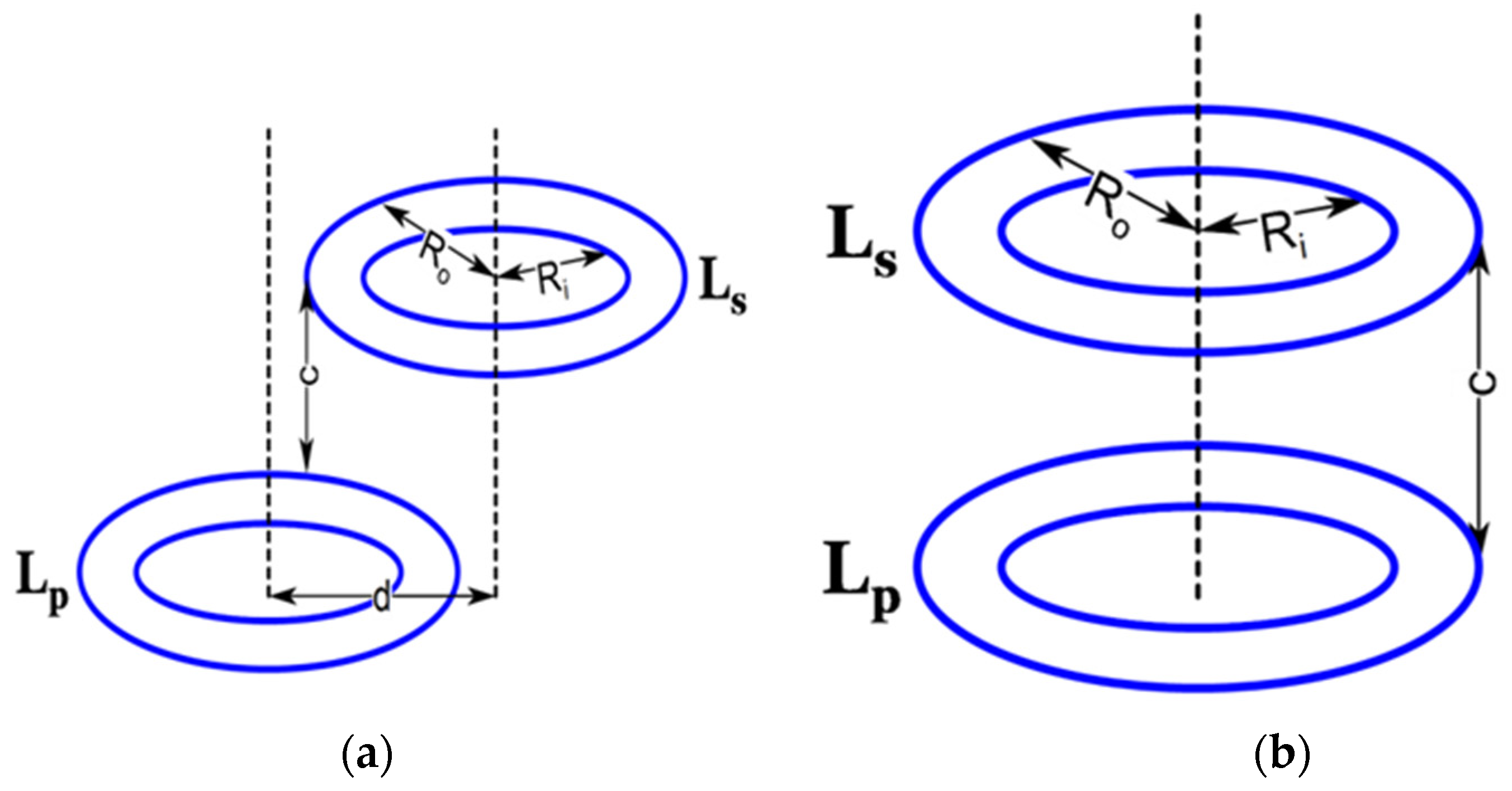
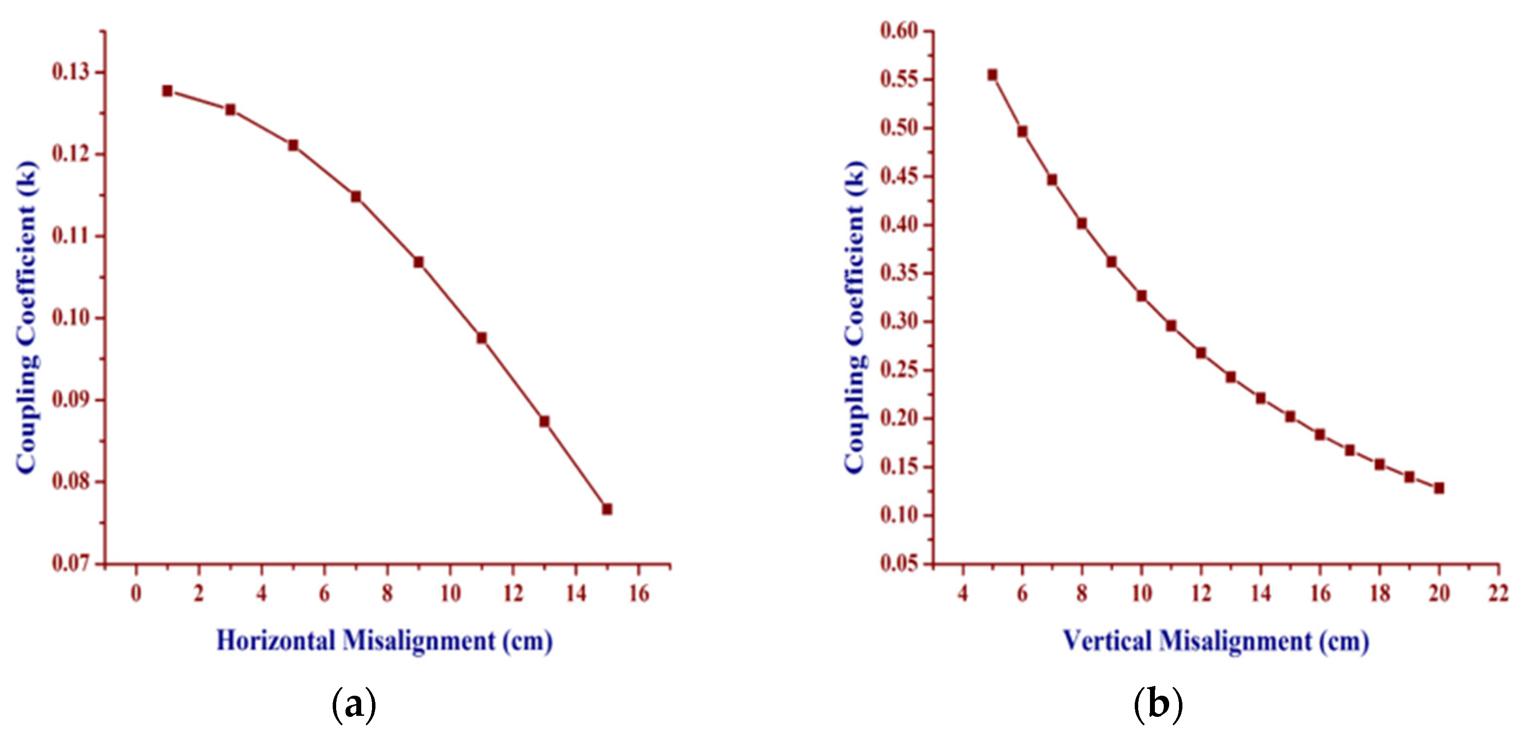
3. Variation in Mutual Inductance

Contingent movement in the pickup coil with respect to the primary coil leads to the variation in mutual inductance [51]. The coil is physically displaced vertically, as well as horizontally, from the center axis. The vertical misalignment is shown in Figure 2a; the horizontal misalignment is shown in Figure 2b. The mutual inductance variation leads to a variation in reflected capacitor value, which, in turn, changes the region of resonance. As a result, the current drawn by the inductive coil varies. The prevailing circumstances are quite often addressed in the literature. The resonance frequency is affected by the variation in mutual inductance. Similarly,
M ij = μ 0 π R p R s 0 π ( 1 d R s cos ) ψ ( k ) V 3 d ϕ
where i and j are the primary and secondary turns in the corresponding coils. d is the distance between the center axis of the primary and secondary coil. Rs and Rp is the radius to the center of primary and secondary coil. Ψ(k) is the function of elliptical integral of first and second kind.
The variation in mutual inductance is expressed as
ψ ( k ) = ( 1 k 2 2 ) K ( m ) E ( m )
Similarly,
V = 1 2 d R s cos + d 2 R s 2
The elliptical integral of first kind is written as
K ( m ) = 0 π 1 1 msin 2 θ d θ
Similarly, the elliptical integral of the second kind is written as
E ( m ) = 0 π 1 msin 2 θ d θ
Finally, the mutual inductance is written as
M = i = 1 N 1 j = 1 N 2 M ij
The coupling coefficient corresponding to the misalignment is noted in Figure 3. The coupling coefficient vs. the horizontal misalignment is shown in Figure 3a; vertical misalignment is shown in Figure 3b. The information is further used for the analysis when the coil is subjected to the coupling coefficient variations. In the case of dynamic IPT systems, the misalignment is an expected course of action. However, the variation in the primary current due to the variation in mutual inductance is always expected. Further, a proper compensation, as well as a proper selection operating frequency, stabilizes the entire IPT system under the contingency in misalignment. Moreover, due to the symmetric nature of the coils, due to misalignment, the flux linkage in the parallel fields is also degraded significantly [53]. The change in mutual inductance changes the frequency of resonance, unlike the conventional resonance circuit. This is explained in the coming section.

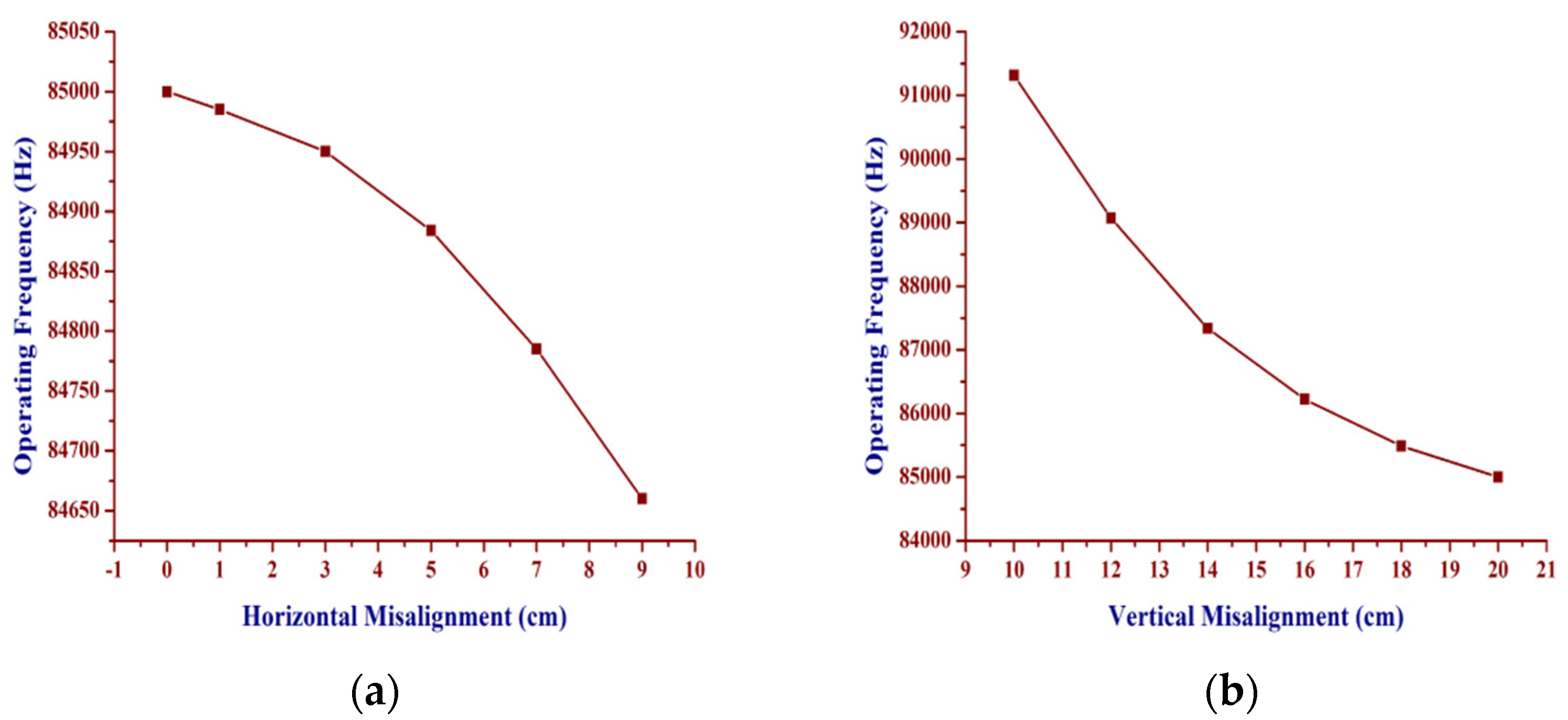
4. Variation in Resonance Frequency

Operating frequency and resonance frequency is determined to comprehend the efficient operating region [51,52,53]. The resonance frequency is written as
ω r = 1 L eq C eq
where Leq is the effective equivalent inductance. Similarly, Ceq is the equivalent capacitance. The values of Lpeq and Ceq are determined based on the circuit topology. The variation of frequency corresponding to the variation in misalignment is noted for the LCL-based IPT system. The obtained data is plotted in Figure 4a,b. The circuit will sustain its condition for resonance under respective frequencies corresponding to the respective misalignment. Increase in operating frequency increases the amount of power transfer capability to larger distances. Selection of switches according to the frequency of operation is quite essential in order to make sure that the circuit meets the needs. Normally, power IGBT cannot be used to attain this because of higher frequency. However, power MOSFET with less turn-on time is highly preferred. In addition, the material used for power MOSFET also plays a vital role in the efficiency of the overall system. This further reduces the occurrence of switching losses in the system. For higher voltage stress, and with high operating frequency, SiC-based MOSFET would be preferred. If the speed of switching is a major concern, GaN-based MOSFETs are preferred. This, in turn, increases the power transfer level from one circuit to the other.

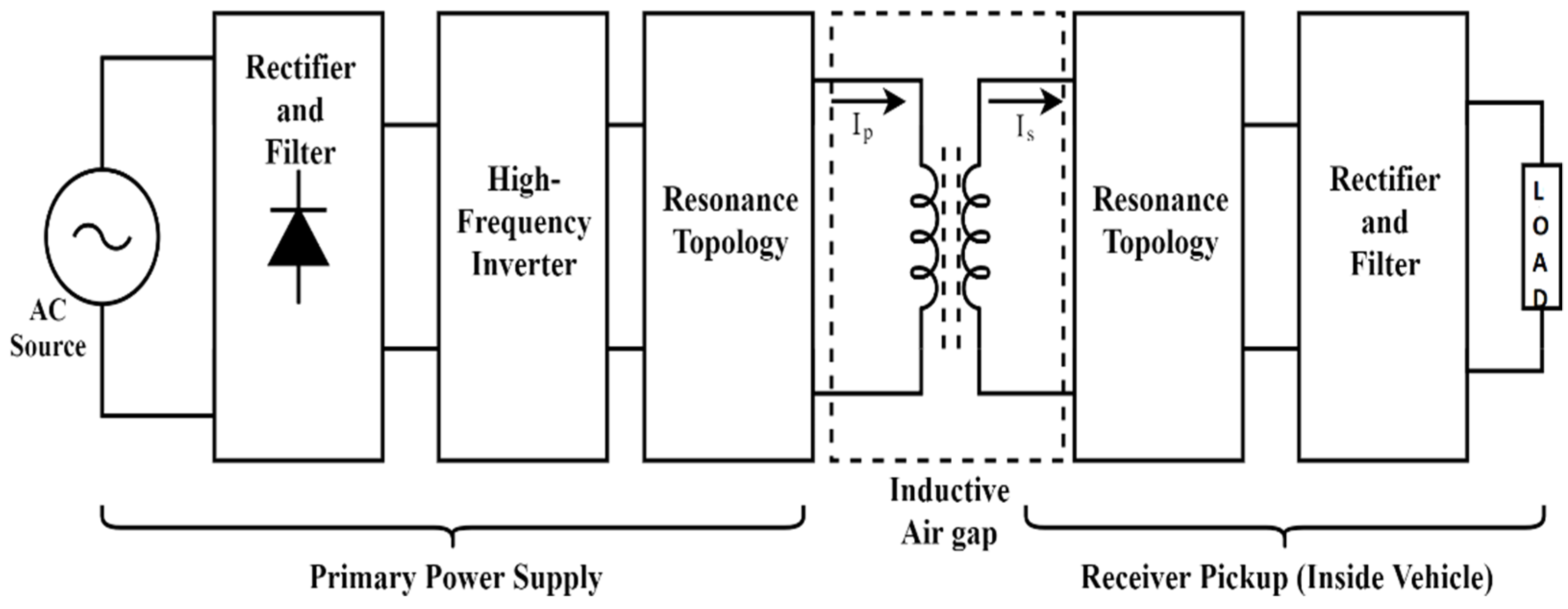
5. Need of Power Converter Topologies

The magnitude, phase and frequency of the current waveform in IPT system is decided by the load, as well as the converter topology connected to it. The need for the high-frequency alternating current to produce a high-frequency electromagnetic field in the transmitting coil is engendered by the high-frequency inverter [41,42]. Similarly, the generated high-frequency-induced voltage in the secondary coil is rectified before being connected to the battery. The aforementioned conversion process is to be attained with minimum losses. This eventually ends with the utilization of power in semiconductor devices. Furthermore, the DC input for the high-frequency inverter is fed from the rectified AC power supply connected to the grid or standalone sources. In order to achieve a high-power factor, an uncontrolled rectifier followed by a DC–DC boost converter is typically used in converter topologies.
There are several resonant converters that are predominant for these applications [43,54,55] The semiconductor switches used in the resonant converters have a greater voltage stress than the conventional converters. Similarly, AC–AC matrix converters are also used to create a high-frequency alternating current [56,57]. The presence of distortion in the waveform due to more switching instances increases the distortion factor and reduces the power factor of the overall system [58]. The material used for the semiconductor switches, especially the use of wide band gap devices, makes the process easier than before [59,60,61]. The most used inverter types are listed below [62].
  • Single phase full bridge inverter
  • Class-E inverter-based IPT system
  • Compact high-efficiency IPT system
The power semiconductor devices, along with energy storage elements, will create the resonance in the circuit with the desired operating frequency.

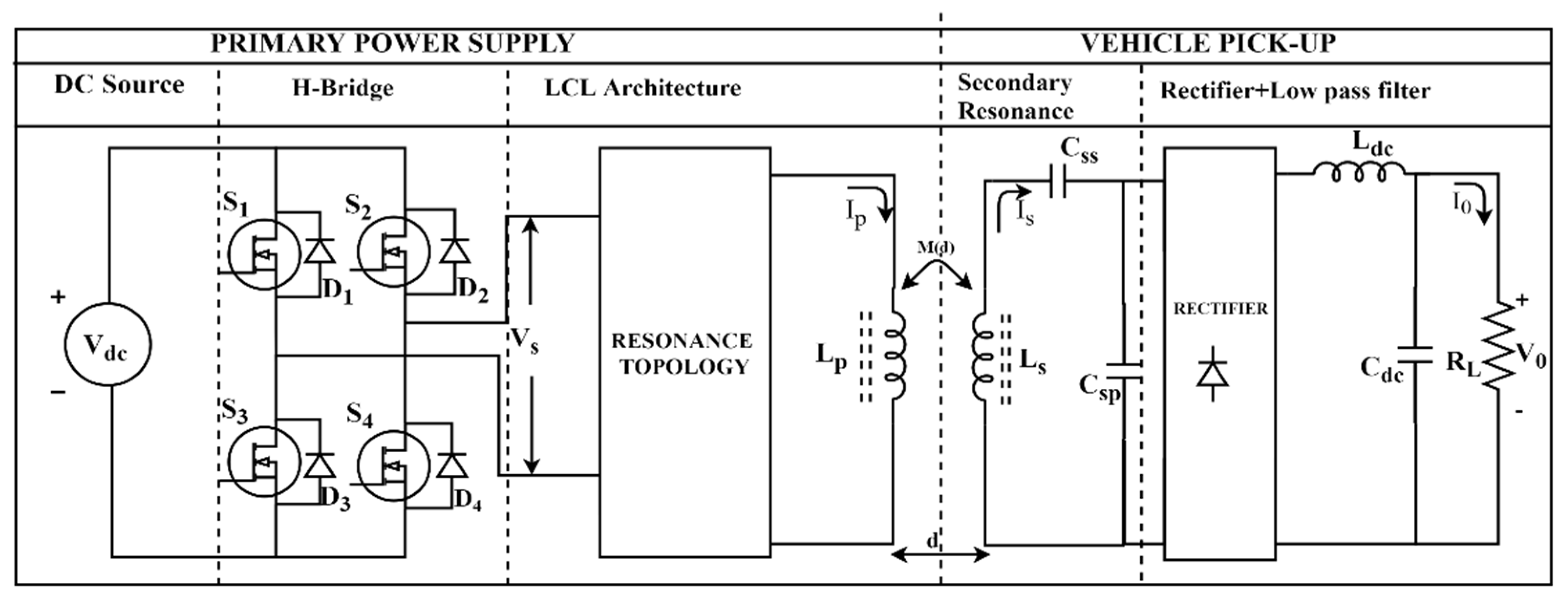
6. H-Bridge Inverter Based IPT System

The H-bridge inverter-based resonance-enhanced IPT system exhibits better power transfer efficiency than the IPT system without resonance. The possibility of the different distinct hybrid resonance topology opens an opportunity to operate the IPT system under different loading conditions. A few significant resonance topologies in the literature are listed below
  • LCL resonance topology
  • SLC resonance topology
  • High-gain LCL resonance topology
The rectified DC supply (VDC) is fed to the H-bridge high-frequency inverter. The inverter gives an output voltage (Vs) with an RMS value of VDC. Furthermore, the resonance branch produces a resonance based on the arrangement of energy storage elements. In general, the following is valid.
v s = V s sin 2 π f o t
The vs. is written in terms of VDC as
V s = 2 2 V DC π sin ( ω o t PS 2 )
tPS is the phase shift time delay in gate pulse. Similarly, fo is the resonance frequency of operation of the inverter in Hz. ωo is the resonance frequency of operation in rad/sec.

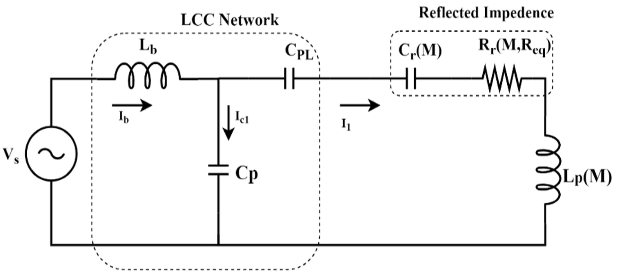
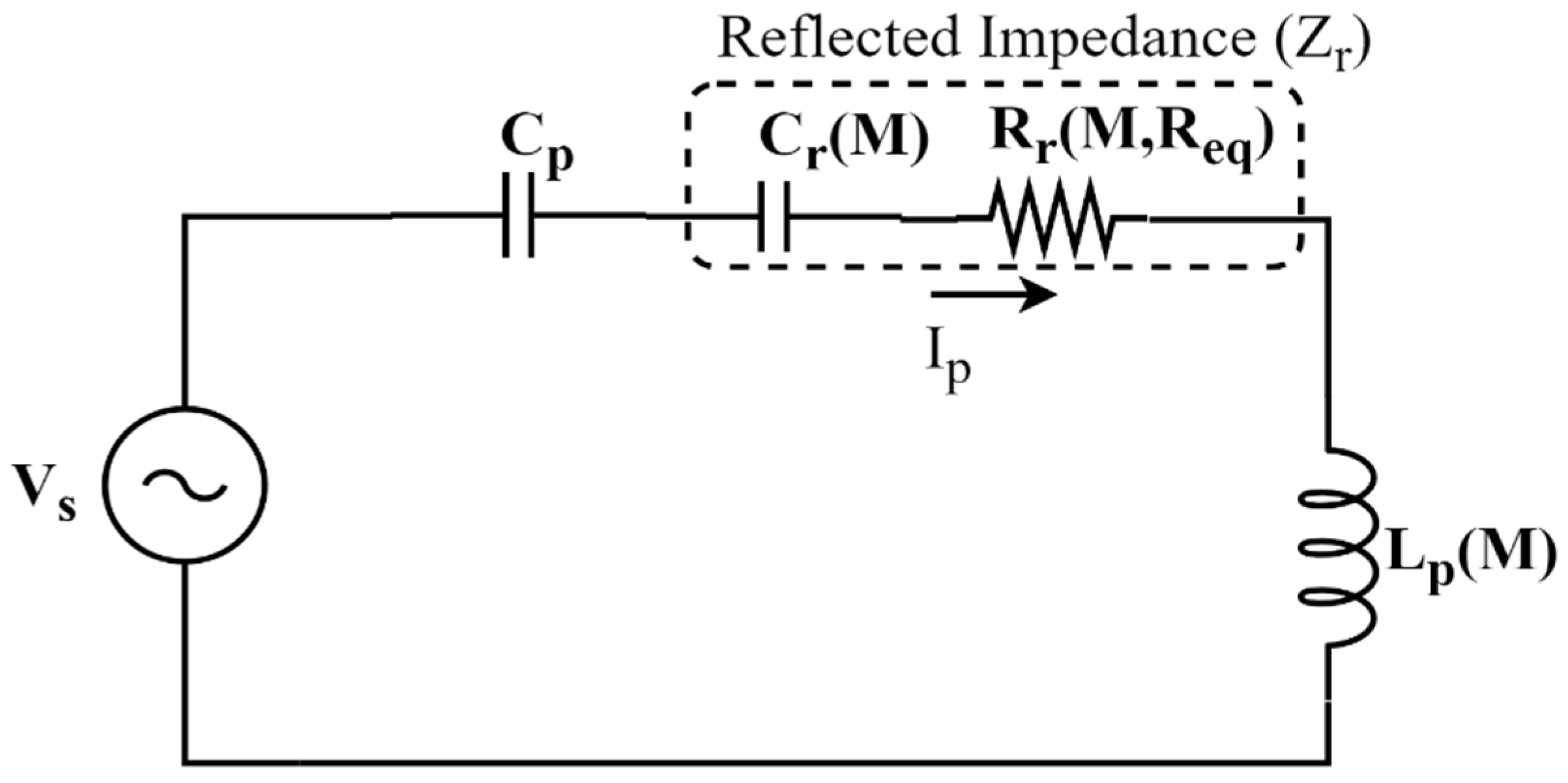
6.1. LCL-Based Resonance Topology

The generalized H-bridge inverter topology is shown in Figure 5. The arrangement of energy storage elements for the equivalent LCL resonance topology is shown in Figure 6. The input AC voltage vs. is fed to the hybrid resonance topology [63,64]. In fact, this topology is an LCC-compensated LCL topology. The primary equivalent inductance is written as:
L peq =   L p 1 ω 2 C PL 1 ω 2 C r
The primary series capacitor is written as
C ps = L seq ω o 2 [ L p L seq M 2 ]
L seq = 1 ω 2 C pp
where M is the mutual inductance between the coil and Cr is the reflected capacitance; CpL is the primary series tuning capacitor. The series capacitance in the circuit and the primary inductor are modified as an equivalent primary inductance. The bridge inductor Lb limits the current flowing from the H-bridge inverter. The capacitor Cp is in resonance with the primary equivalent inductor Lpeq. The tuning of the primary compensations capacitances allows the LCL-based IPT system to operate over a wide load range. The reflected capacitance is a function of misalignment. The changes in equivalent inductance due to the significant changes in misalignment are limited. This eventually reduces the change needed in the frequency of the operation to maintain the condition of resonance under misalignment.

6.2. SLC-Based Resonance Topology

The arrangement of energy storage elements for the equivalent SLC resonance topology is shown in Figure 7. The primary compensation capacitance (Cp) can be written as:
C p = L seq ω o 2 [ L p L seq M 2 ]
where the change in the value of inductance due to primary equivalent inductance is written as:
L p = L p L peq
In particular, the second order resonance in the IPT with a different combination can be achieved with the arrangement of the energy storage elements. The resonance combination, such as series–series (SS), series–parallel (SP), parallel–series (PS), parallel–parallel (PP) combinations are possible based on the arrangement of energy storage elements [65,66,67]. The series inductor–capacitor (SLC) topology has high efficiency, while delivering a high load. Similarly, the converter has poor light load efficiency.

6.3. High-Gain LCL Topology

The high-gain LCL topology is particularly designed for high DC–DC voltage gain. This, in turn, reduces the required input voltage level.
The simplified circuit of the high-gain LCL-based IPT system is shown in Figure 8. The conventional LCL configuration is modified in such a way that the primary parallel capacitor supplies more reactive power than the conventional one. The combination of back-to-back connected semiconductor switches encompasses the bidirectional flow of the current. The equivalent secondary equivalent capacitance is written as:
C seq = 1 ω 2 C eq
where Ceq is a combination of capacitance Cg and Cp. In all these topologies, the reflected capacitance is written as,
C r ( M , R eq ) = R eq 2 ( ω 2 C sp L seq 1 ) 2 + ( ω L seq ) 2 ( ω 4 M 2 ) [ C sp R eq 2 ( ω 2 C sp L seq 1 ) 2 + L seq ]
From Equation (16), it is clear that the reflected capacitance is a function of the mutual inductance. The mutual inductance is a function of misaligned distance between the coils. Further, the resonance operating frequency is a function of reflected capacitance [23]. Hence, the reflected resistance Rr (M, Req) is written as:
R r ( M , R eq ) = R eq ( ω M ) 2 [ ω 2 C sp L seq ( ω 2 C sp L seq 1 ) ] R eq 2 ( ω 2 C sp L seq 1 ) 2 + ( ω L seq ) 2  
The high-gain LCL-based IPT system has higher voltage gain than the conventional LCL- and SLC-based topology under misalignment. Compared to the other predominant architecture, the voltage gain is higher even at a loosely coupled range. This eventually makes the converter beneficial for an IPT system with large misalignment.
During the time of resonance, the term in denominator ω 2 C sp L seq approaches 1; the term that depends on R eq vanishes. This eventually conveys that the changes in load during the resonance are not going to impact the resonance frequency of the system. The open circuit voltage is the function of mutual inductance and primary current. Hence, for a loosely coupled system, the secondary current is also reduced. The secondary resonance topology plays an important role in frequency of operation and magnitude of primary current. The reflected capacitance is calculated based on the arrangement of secondary circuit elements.

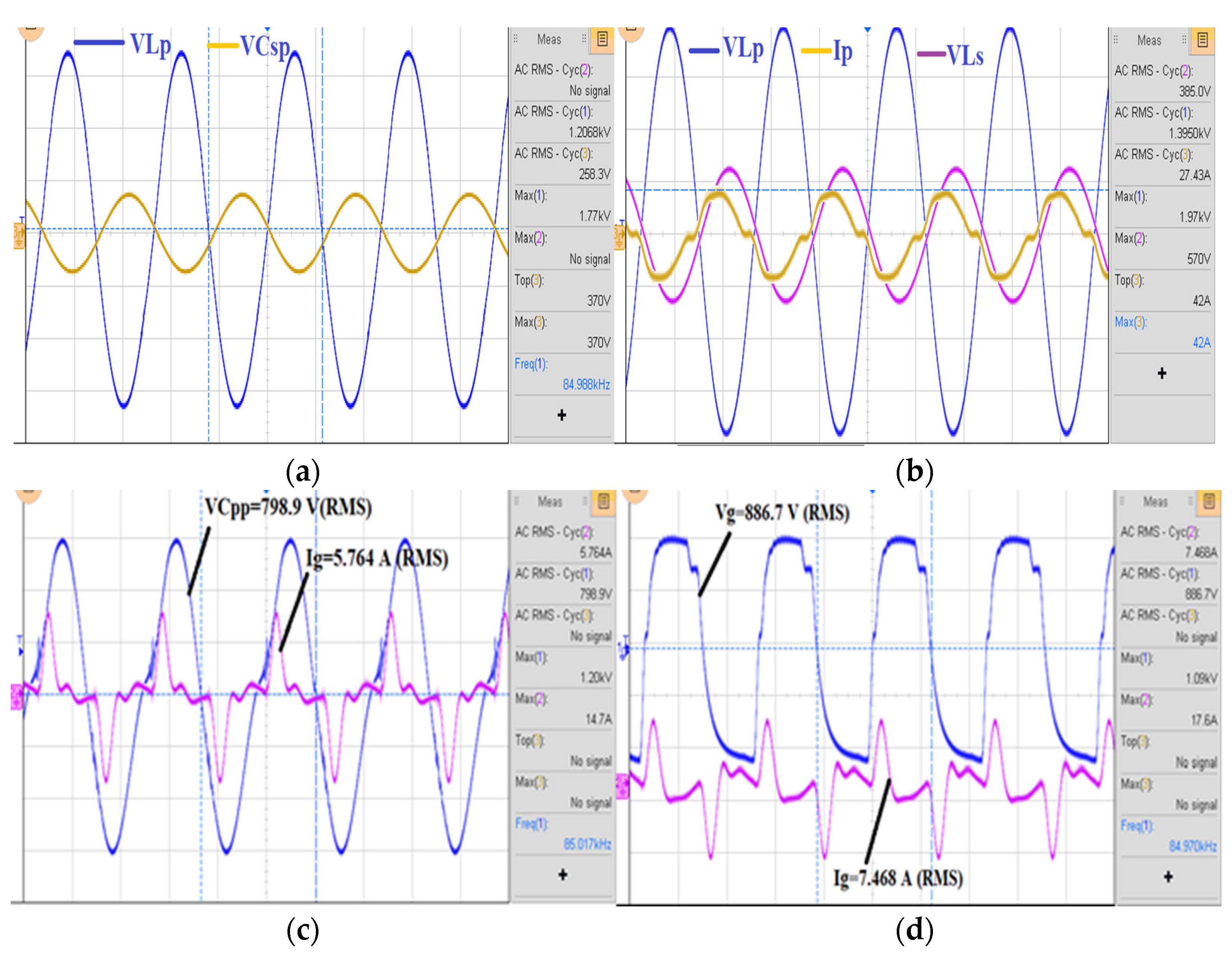
6.4. Relevant Experimental Waveforms

Experimental studies were conducted on a 1 kW high-gain LCL-based IPT system, and the results are shown in Figure 9. The additional gain capacitor Cg in the high-gain topology injects more current to the inductive track. The voltage across the primary winding Lp and secondary winding Ls are shown in Figure 9a. Similarly, the primary current Ip and the current through the gain capacitor Cg are shown in Figure 9b,c. The voltage across the gain capacitor is shown in Figure 9d.

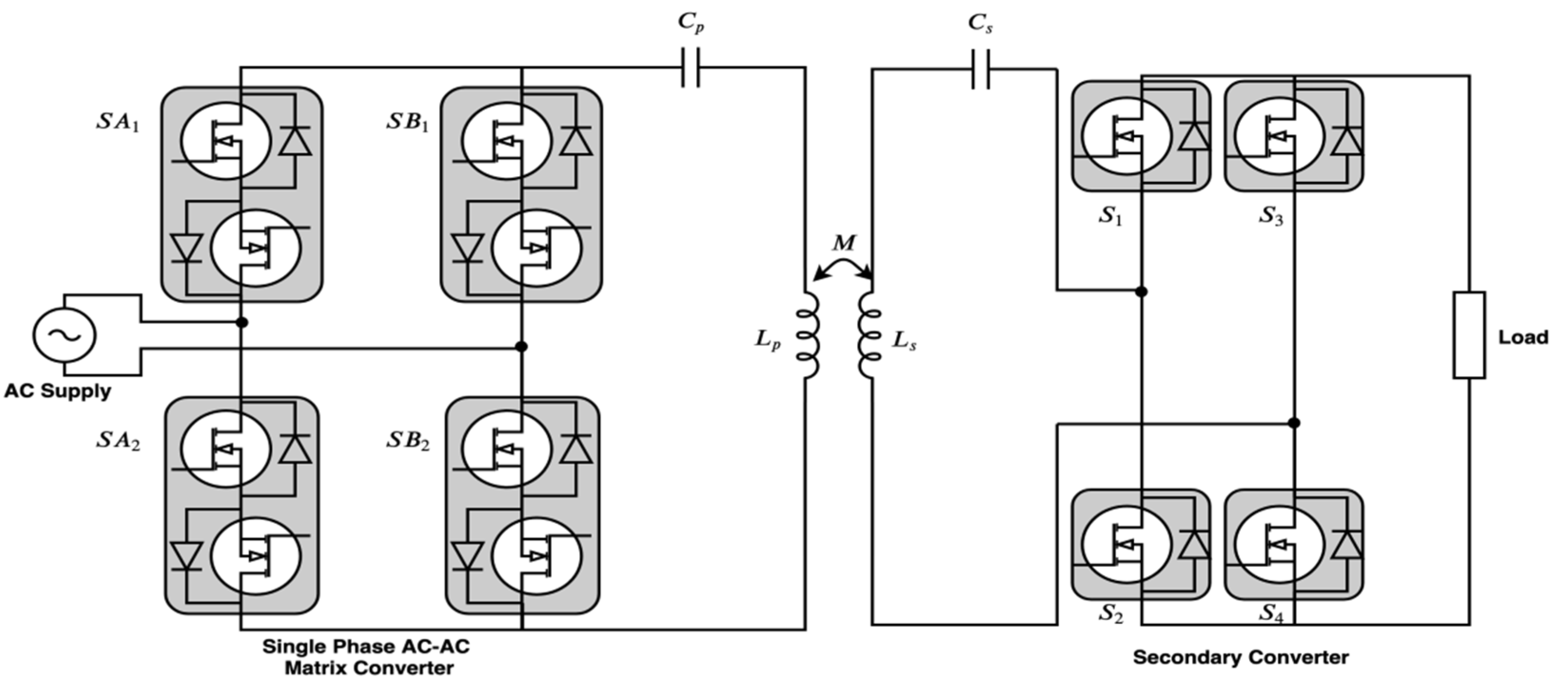
7. Direct AC–AC Conversion

In the case of conventional IPT systems, the high-frequency inverted AC supply is generated from a DC source using the high-frequency inverter [53,57]. This way of generating high-frequency AC from the available AC source with lower frequency exhibited more power loss due to a greater number of conversion stages.

7.1. Matrix Converter

In the present scenario, matrix converters completed this job effectively. The matrix converters made the bidirectional power flow more easily than other converters. Since the energy storage elements were reduced more than the conventional one, the system exhibited high-power density. This made the system more reliable. However, a greater number of bidirectional semiconductor switches makes the operation complex.
The quality of output voltage and current was poor in this approach. The synchronous operation of semiconductor switches needed special care. The switches needed to be soft-switched to maintain better efficiency. A typical matrix converter-based IPT system is shown in Figure 10. The fundamental harmonic of the resonant current is written as:
I 1 mn = V 1 mn R eq = ± ( m + n ) | V ac | 4 π R eq
Power transfer rate is represented as
P t = 1 2 R eq ( I 1 mn ) 2 = ( m + n ) 2 V ac 2 32 π 2 R eq
where Pt is the instantaneous power transfer rate. The average power transfer rate is given as:
P m = ( m + n ) 2 V AC 2 32 π 2 R eq
where, Req is the reflected equivalent resistance to the primary.

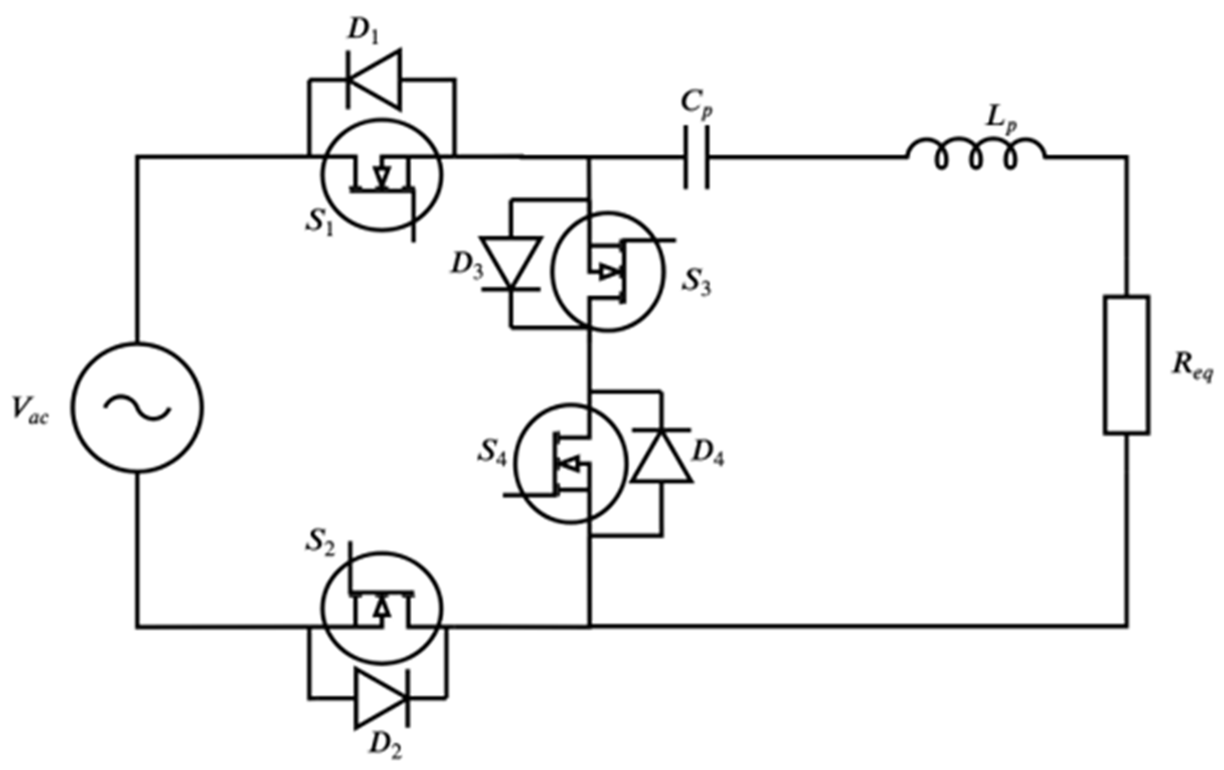
7.2. Direct AC–AC Converter

The major disadvantages of matrix converters can be overcome by using a direct AC–AC converter. This converter also converts low frequency AC supply to high-frequency AC supply. A typical converter is shown in Figure 11. The converter uses the technique of free oscillation and energy injection control. This unique topology allows for bidirectional power transfer. The secondary circuit elements are reflected to the primary side. The primary inductance is lumped. A series tuning capacitor with the lumped inductor creates the resonance in the circuit. Vp is the voltage across the switches S3.
v p = { V ac sin β ( Injection ) 0   ( Oscillation )
The complete expression for track current is given as
i L = v C ( 0 ) ω L e t / τ sin ω t + i L ( 0 ) ω 0 ω e t / τ cos ( ω t + θ )
where vC (0) and iL (0) initial voltage and current of the capacitor and inductor respectively. τ = 2L/Re. The resonance frequency ωo = 1/LC.
The higher number of switching in these matrix converters will worsen the THD and power factor. In view of that, significant improvement is needed in this converter before it can be applied to EV charging. Currently, the converter will pose challenges for EMC compliance testing. Hence, the converter is not a good solution for the IPT system as such. In the coming section, the Class-E-based IPT system is explained.

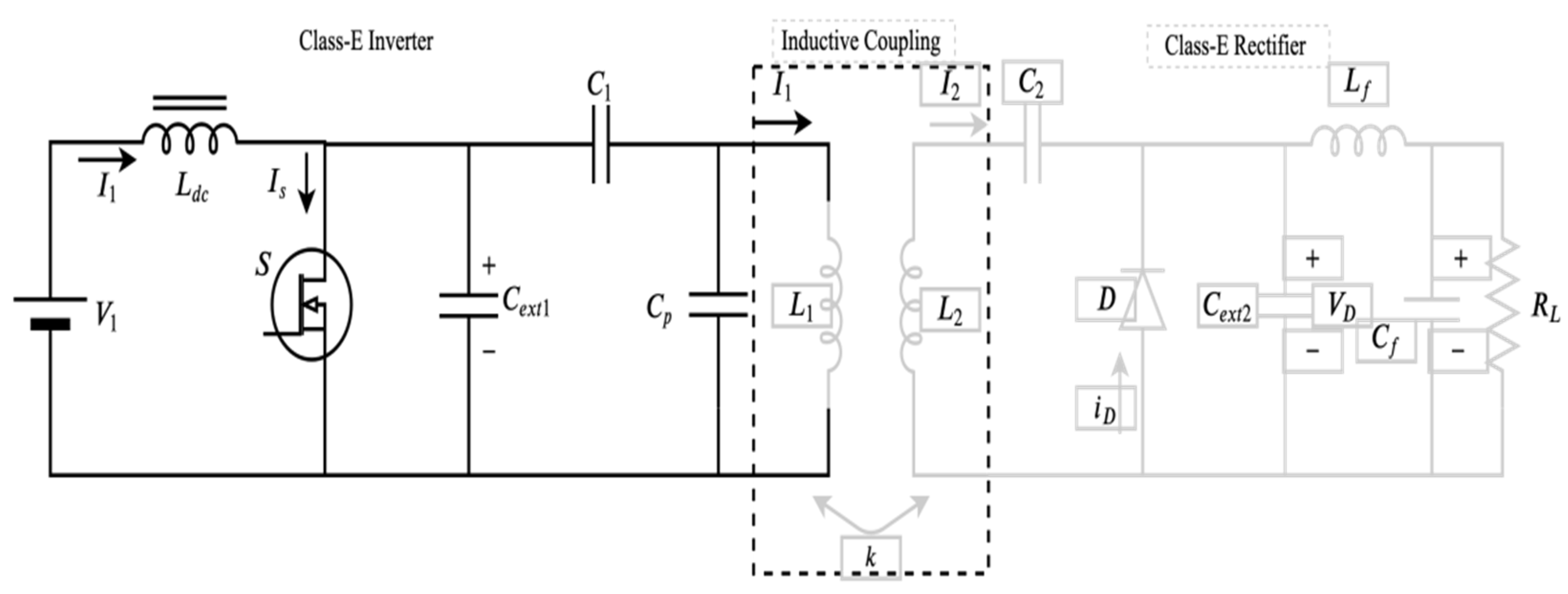
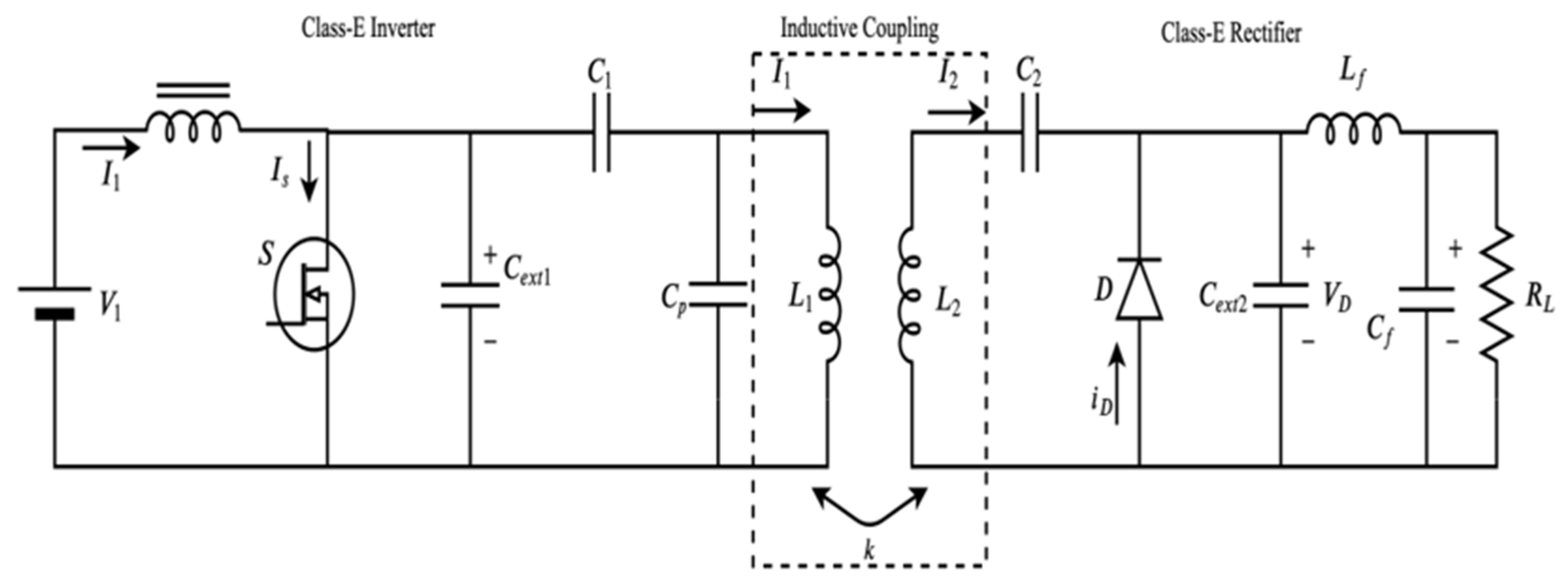
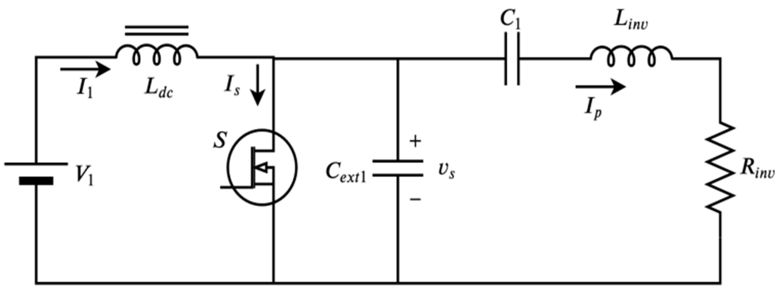
8. Class-E Based IPT System

The Class-E-based topology with a reduced number of semiconductor switches brings the possibility to transfer the power in an efficient way [68,69,70]. Moreover, it will increase the compactness of the system. The available conventional Class-E types of converters are operated at a high frequency with a high-quality factor. This, in turn, reduces the size of components used in the circuit. A general Class-E type inverter is shown in Figure 12.

8.1. Class-E Inverter

The Class-E inverter is also a major player in creating the high-frequency alternating current required for the inductive coil. The embedded resonance topology, along with the inductive coil, makes the circuit simple and compact. For analysis, all the secondary linearly-approximated energy storage elements, along with the equivalent resistance, are referred to the primary side in order to calculate the effective impedance seen by the source. The inverter is operated in the MHz range in order to maintain a high-quality factor in the secondary circuit. The resonance series capacitor C1 and impedance transformation capacitance Cp are shown in Figure 12. The linear approximated elements of the Class-E rectifier are referred to the primary side of the Class-E based IPT system. The Linv and Rinv is represented as [26,42,43]
R inv = ( R eq + r L 1 ) ω 2 C p 2 [ ( R eq + r L 1 ) 2 + ( ω L eq 1 ω C p ) 2 ]
L inv = L eq ( 1 ω 2 L eq C p ) C p ( R eq +   r L 1 ) 2 ω 2 C p 2 [ ( R eq + r L 1 ) 2 + ( ω L eq 1 ω C p ) 2 ]
where, Rinv and Linv are the corresponding simplified inverter equivalent inductance and resistance values in terms of other circuit elements. The capacitor C1 is in series with Linv and Rinv, which makes a series resonance circuit. The switching pattern of the inverter can be obtained by proper analysis.

8.2. Class-E2 WPT System

The Class-E rectifier is a single switched topology used to rectify at higher switching frequency with less voltage ripple. The single diode is connected as a half-wave rectifier.
Figure 13 shows the Class-E2 WPT system. The system is comprised of the Class-E inverter and the Class-E rectifier.
The Class-E inverter consists of a single semiconductor switch S, connected as shown in Figure 14. The input capacitance C i can be represented as
C i = 4 π C D 4 π ( 1 D d ) + 4 sin ( 2 π D d )   sin ( 4 π D d ) cos ( 2 d ) 2 sin ( 2 d )
where, Ci is the input capacitance and CD is the parasitic shunt capacitance of the MOSFET. Similarly, the input resistance of the rectifier (Ri) is written as:
R i = 2 R L sin 2   d
The phase shift (Ød) is written as
tan d = 1 cos ( 2 π D d )   2 π ( 1 D d ) + sin ( 2 π D d )
where, Dd is the diode on duty ratio and Ød is the phase shift between the voltage and current.

8.3. Coupling Circuit

The equivalent resistance is written as
R eq = k 2 ω 2 L 1 L 2 ( rL 2 + R i ) ( rL 2 + R i ) 2 + ( ω L 2 1 ω C r ) 2
The equivalent inductance is written as
L eq = k 2 L 1 ( rL 2 + R i ) 2 L 2 C r + ( 1 ω C r ) 2 rL 2 + L 1 ( 1 k 2 )
where k is the coupling coefficient and L1, L2 are the primary and secondary inductance. Similarly, rL2 is the internal resistance of the secondary pickup coil and Cr is the reflected capacitance. Using Req and Leq the Class-E inverter is simplified into (28) and (29).
These Class-E-based and -derived circuit topologies are promising solutions for the future. Since there is a reduction in the number of semiconductor switches and energy storage elements for a similar power rating, the future IPT system can achieve higher-power density. However, if the circuit topology is to be used for electric vehicles, a significant improvement is needed. The disability of these Class-E converters is addressed in the next section, where the circuit has been viewed from a different perspective.

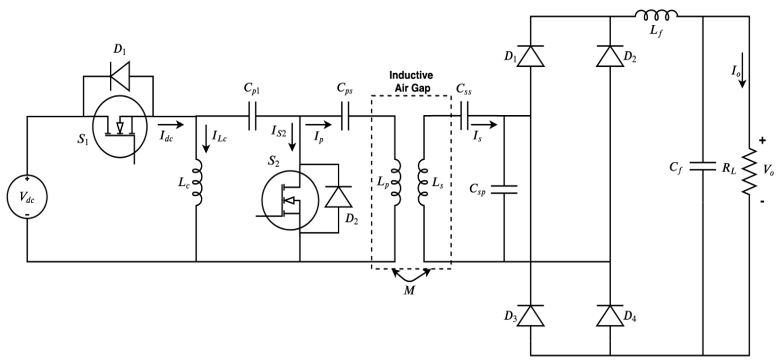
9. Compact High-Efficiency IPT System

The compact high-efficiency IPT system is another interesting topology that is different in its operation compared to the conventional one; it is shown in Figure 15. Here, the high-frequency inverter is operated based on pulse position.
The secondary pick-up coil is connected to an uncontrolled rectifier through a proper compensation capacitor combination. Further, the rectifier is connected to the load through a low pass filter. The switches S1, S2 and diodes D1, D2 plays a vital role in making a high-frequency AC supply.
The resonance circuit is embedded into the topology such that the energy storage and energy transfer take place through the semi-conductor devices. Moreover, better control on the resonance can be achieved using this converter when comparing to the LCL topology.

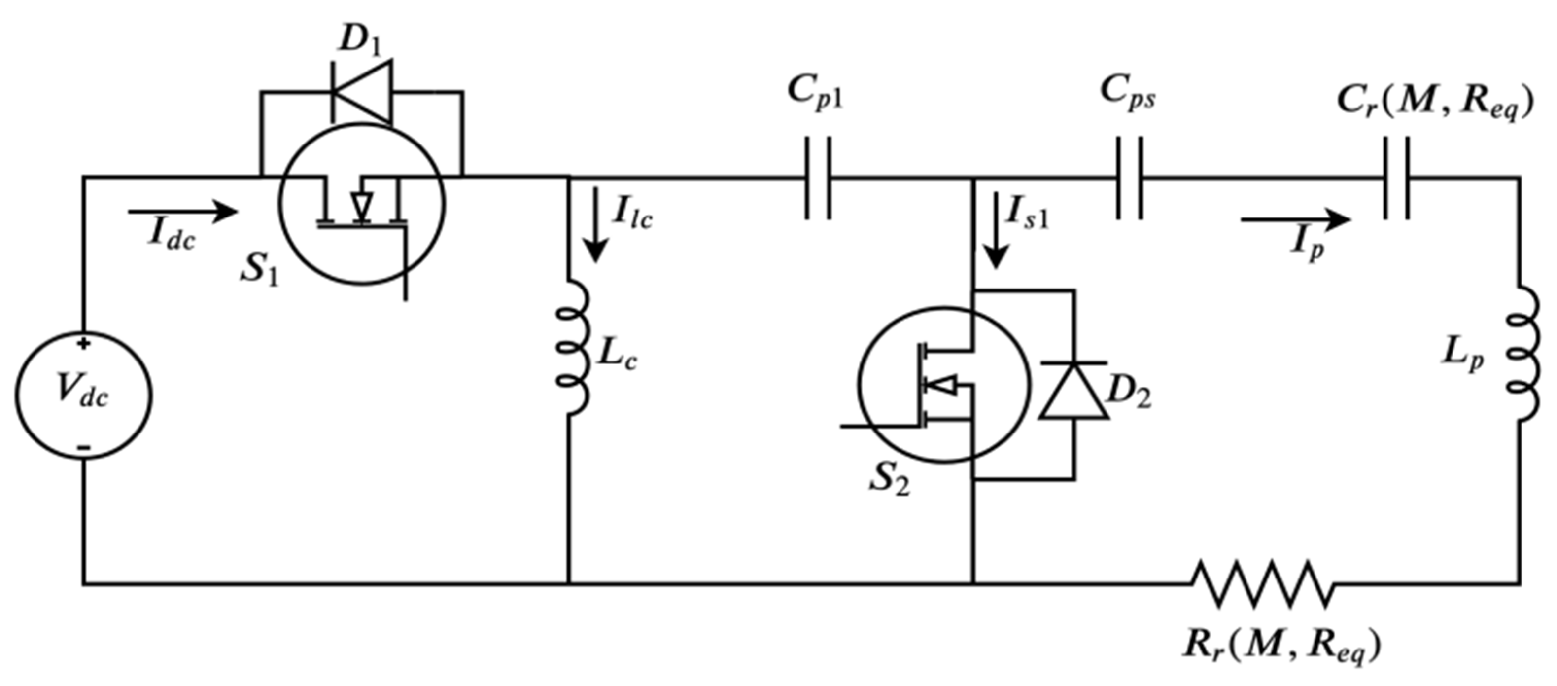
9.1. Equivalent Circuit

The equivalent circuit of the compact high-efficiency IPT system is shown in Figure 16. The equivalent secondary circuit elements primarily referred to the primary elements of the IPT system. The power drawn by the reflected branch is transferred to the secondary circuit. The charging inductor Lc is charged when the switch S1 is turned on as the diode D1 is forward-biased. The switch S1 and S2 are turned on complimentarily. The current through the inductor Lc passes after the withdrawal of the gate pulse from the switch S1 due to the conduction of the body diode. In the case of a discharge of the inductor current, switch S2 and the corresponding body diode conduct. This process leads to the operation of the inverter based on pulse position rather than the pulse width. The primary current through the inductive coil is written as
I p = V dc ω C p 1 R r ω C p 1 j   ( 1   ω 2 L seq C p 1 )
Similarly, the secondary track current is written as
i s ( t ) = I sm sin ( ω t )
where,
= tan 1   { ω L seq   R eq ( 1 ω 2 L seq C sp ) }

9.2. Experimental Waveforms

An experimental prototype was developed for a 1 kW compact high-efficiency IPT system; relevant experimental waveforms are shown in Figure 14. The voltage across the primary and secondary inductors are shown in Figure 17a. The additional primary current along with the voltage waveform is shown in Figure 17b. Similarly, voltage across the charging inductor (Lc) gate pulse, along with primary voltage, is shown in Figure 17c. In addition, the secondary current with the voltage across the charging inductor is shown in Figure 17d.

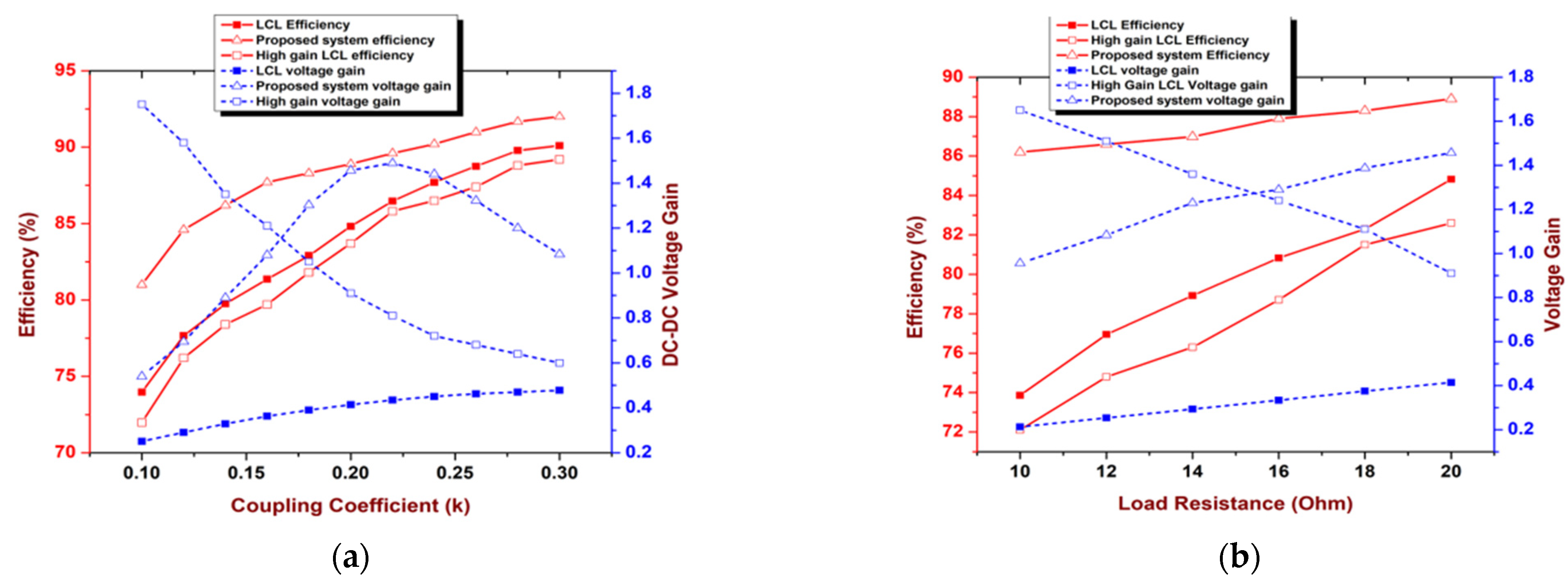
10. Comparison of Topologies

Every topology has unique benefits based on the type of load connected to it. The existing predominant topologies are compared based on the variation in efficiency and voltage gain and are shown in Figure 18. Further, different influential parameters were considered; the findings are shown in Table 4 [71]. The steady state resistance of a battery is subjected to change if there is a change in the charging current and the voltage. There is a gradual decrease in average current while the battery is getting charged. Otherwise, there will be a high current during the initial time of charging. This, in turn, provides high steady state resistance. The reflected resistance from the load side is subjected to change, for the same reason. The effect in this variation was studied and is discussed in this section. The variation in efficiency and voltage gain against the load resistance is shown in Figure 18b. The diode bridge at the receiving end is non-linear. An equivalent linear approximated resistance for the diode bridge is calculated based on the ratio of fundamental rms voltage to the fundamental rms current. In LCL-based IPT systems, the equivalent resistance is written as:
R eq = π 2 R L 8
where, RL is the load resistance and Req is the equivalent steady state resistance. Due to the variation in load, current is taken by the coil changes. However, within the permissible limit of the coupling coefficient, say 0.12 to 0.2, the variation in the current can be handled by the converter. The occurrence of the fault and short circuit may lead to draw heavy current from the supply. This can be anticipated; the converter can be designed accordingly to meet these needs. A lower number of semiconductor devices is used in a compact high-efficiency topology. In case of a high-gain LCL topology, more semi-conductor devices are used. However, these two topologies are used for two distinct purposes. Above all, these two topologies portray two different characteristics for different load variations.
The conventional LCL topology is predominant in this field due to its consistent operation. From Figure 18b, it can be observed that the efficiency of LCL topology reduces at lower coupling coefficient under misalignment. Similarly, the voltage gain of high-gain LCL topology is very high at the lower coupling coefficient. The efficiency of compact high-efficiency topology varies between 86.2% to 89.1% during the load variations, whereas, for LCL, it is 74% to 84.9%. In the case of Class-E and high-efficiency topology, the voltage stress across the switch is high compared to the LCL, high gain and SLC topology. The operating frequency is in the range of MHz for Class-E-based topology. All other topologies can be operated in SAE and QI standards. The high-gain LCL topology can be operated in both LCL as well as high-gain mode. Hence, the same characteristics of LCL topology can attain using high-gain LCL topology. The high-efficiency topology has more control freedom than the other existing topologies. Table 4 presents a comparative analysis of the different WPT technologies available currently with respect to various parameters. It can be observed that the IPT (or magnetic resonant WPT) is the most mature among all other near field WPT technologies. Although there are a few drawbacks, the sophistication offered by the WPT system has led to the testing and implementation of several prototypes for dynamic charging (which is the most challenging mode) via magnetic resonance.

11. Future Trends

The future of the inductive power transfer system for electric vehicles needs more advancement in material, technology and maturity in industrial practices [25,26,71,72,73]. The use of Litz wire and film capacitors also need further advancement. The size and shape of the inductive coil is also a further scope. Thermally conductive polymer helps in thermal management in inductive coils. The performance of the converter is limited due to one or two components. The improvement in this would be a breakthrough in research. This is especially true for high-power inductive power transfer systems [74]. The power transfer efficiency also improved by reducing the losses. To achieve high-power density at a higher operating frequency is also a scope of further research in this field. Dynamic inductive power transfer is one of the effective ways to reduce the storage capacity of the vehicle. In this method, the vehicle will be charged under the motion. The key challenge for the same case will be the infrastructure and electrification. On the other end, there are many benefits, such as reducing the charging time, battery capacity, etc. As the generation in online electric vehicles (OLEV) increases, the power transfer distance increases [75]. A similar approach is adopted in powering high-speed trains [76,77,78]. The speed of the train is high; maintaining a constant power supply at the secondary pickup coil is a challenge.

12. Conclusions

The role of semiconductor power devices in inductive power transfer was comprehensively analyzed.
  • The different circuit topologies were compared with different aspects in order to identify and discriminate the significance of each topology.
  • It was observed that LCL-based resonance topology is preferred for a wide range of loads, whereas SLC is not suitable for light loaded applications.
  • More semiconductor switches made the matrix converter complex in operation. However, it ensured the bidirectional power flow with high-power density.
  • In the case of compactness and efficiency, compact high-efficiency topology was more promising.
  • Similarly, if the available input DC source voltage is lower, a high-gain LCL topology is preferred.

Author Contributions

Conceptualization, S.V. and F.D.J.L.; methodology, S.V. and F.D.J.L.; software, S.V. and F.D.J.L.; validation, S.V. and F.D.J.L.; formal analysis, F.D.J.L. and M.K.S.; investigation, F.D.J.L. and M.K.S.; writing—original draft preparation, S.V., F.D.J.L. and M.K.S.; writing—review and editing, F.D.J.L., M.K.S., R.K., S.W., L.I.I.; supervision, R.K., S.W., F.D.J.L.; project administration, L.I.I. All authors have read and agreed to the published version of the manuscript.

Funding

This research was supported by (Yayasan UTP Fundamental Research) under the grant number (Y-UTP 015LCO-134).

Institutional Review Board Statement

Not applicable.

Informed Consent Statement

Not applicable.

Data Availability Statement

Not applicable.

Acknowledgments

This research work has been in collaboration with Universiti Teknologi PETRONAS, Malaysia.

Conflicts of Interest

The authors declare no conflict of interest.

References

  1. Bosshard, R.; Kolar, J.W. Inductive Power Transfer for Electric Vehicle Charging: Technical Challenges and Tradeoffs. IEEE Power Electron. Mag. 2016, 3, 22–30. [Google Scholar] [CrossRef]
  2. Mayordomo, I.; Drager, T.; Spies, P.; Bernhard, J.; Pflaum, A. An Overview of Technical Challenges and Advances of inductive Wireless Power transmission. Proc. IEEE 2013, 101, 1302–1311. [Google Scholar] [CrossRef]
  3. Dai, J.; Ludois, D.C. A Survey of Wireless Power Transfer and a Critical Comparison of Inductive and Capacitive Coupling for Small Gap Applications. IEEE Trans. Power Electron. 2015, 30, 6017–6029. [Google Scholar] [CrossRef]
  4. Wang, C.-S.; Covic, G.A.; Stielau, O.H. Investigating an LCL Load Resonant Inverter for Inductive Power Transfer Applications. IEEE Trans. Power Electron. 2004, 19, 995–1002. [Google Scholar] [CrossRef]
  5. Knecht, O.; Kolar, J.W. Performance Evaluation of Series-Compensated IPT Systems for Transcutaneous Energy Transfer. IEEE Trans. Power Electron. 2018, 34, 438–451. [Google Scholar] [CrossRef]
  6. Choi, B.-H.; Lee, E.S.; Huh, J.; Rim, C.T. Lumped Impedance Transformers for Compact and Robust Coupled Magnetic Resonance Systems. IEEE Trans. Power Electron. 2015, 30, 1. [Google Scholar] [CrossRef]
  7. Mohamed, A.A.S.; Meintz, A.; Schrafel, P.; Calabro, A. Testing and Assessment of EMFs and Touch Currents From 25-KW IPT System for Medium-Duty EVs. IEEE Trans. Veh. Technol. 2019, 68, 7477–7487. [Google Scholar] [CrossRef]
  8. Prasanth, V.; Bauer, P. Distributed IPT Systems for Dynamic Powering: Misalignment Analysis. IEEE Trans. Ind. Electron. 2014, 61, 6013–6021. [Google Scholar] [CrossRef]
  9. Wu, H.H.; Gilchrist, A.; Sealy, K.D.; Bronson, D. A High Efficiency 5 KW Inductive Charger for EVs Using Dual Side Control. IEEE Trans. Ind. Inf. 2012, 8, 585–595. [Google Scholar] [CrossRef] [Green Version]
  10. Huang, L.; Hu, A.P.; Swain, A.; Dai, X. Comparison of Two High Frequency Converters for Capacitive Power Transfer. In Proceedings of the 2014 IEEE Energy Conversion Congress and Exposition (ECCE), Pittsburgh, PA, USA, 14–18 September 2014; Institute of Electrical and Electronics Engineers (IEEE): Piscataway, NJ, USA, 2014; pp. 5437–5443. [Google Scholar] [CrossRef]
  11. Banerji, A.; Datta, T.; Bandyopadhyay, G.; Biswas, S.K.; Banerji, A.; Banerji, A. Wireless Transfer of Power: Status and Challenges. In Proceedings of the 2016 International Conference on Intelligent Control Power and Instrumentation (ICICPI), Kolkata, India, 21–23 October 2016; Institute of Electrical and Electronics Engineers (IEEE): Piscataway, NJ, USA, 2016; pp. 251–257. [Google Scholar] [CrossRef]
  12. Funato, H.; Kobayashi, H.; Kitabayashi, T. Analysis of Transfer Power of Capacitive Power Transfer System. In Proceedings of the 2013 IEEE 10th International Conference on Power Electronics and Drive Systems (PEDS), Kitakyushu, Japan, 22–25 April 2013; Institute of Electrical and Electronics Engineers (IEEE): Piscataway, NJ, USA, 2013; pp. 1015–1020. [Google Scholar] [CrossRef]
  13. Marincic, A. Nikola Tesla and the Wireless Transmission of energy. IEEE Trans. Power Appar. Syst. 1982, 10, 4064–4068. [Google Scholar] [CrossRef]
  14. Shevchenko, V.; Husev, O.; Strzelecki, R.; Pakhaliuk, B.; Poliakov, N.; Strzelecka, N. Compensation Topologies in IPT Systems: Standards, Requirements, Classification, Analysis, Comparison and Application. IEEE Access 2019, 7, 120559–120580. [Google Scholar] [CrossRef]
  15. Patil, D.; McDonough, M.K.; Miller, J.M.; Fahimi, B.; Balsara, P.T. Wireless Power Transfer for Vehicular Applications: Overview and challenges. IEEE Trans. Transp. Electrif. 2018, 4, 3–37. [Google Scholar] [CrossRef]
  16. Boys, J.T.; Covic, G.A. The Inductive Power Transfer Story at the University of Auckland. IEEE Circuits Syst. Mag. 2015, 15, 6–27. [Google Scholar] [CrossRef]
  17. González-González, J.M.; Triviño-Cabrera, A.; Aguado, J.A. Design and Validation of a Control Algorithm for a SAE J2954-Compliant Wireless Charger to Guarantee the Operational Electrical Constraints. Energies 2018, 11, 604. [Google Scholar] [CrossRef] [Green Version]
  18. Cai, A.; Pereira, A.; Tanzania, R.; Tan, Y.K.; Siek, L. A High Frequency, High Efficiency GaN HFET Based Inductive Power Transfer System. In Proceedings of the 2015 IEEE Applied Power Electronics Conference and Exposition (APEC), Charlotte, NC, USA, 15–19 March 2015; Institute of Electrical and Electronics Engineers (IEEE): Piscataway, NJ, USA, 2015; pp. 3094–3100. [Google Scholar] [CrossRef]
  19. Lu, M.; Ngo, K.D.T. Systematic Design of Coils in series–series Inductive Power Transfer for Power Transferability and Efficiency. IEEE Trans. Power Electron. 2018, 33, 3333–3345. [Google Scholar] [CrossRef]
  20. Varikkottil, S.; Daya, J.F. High-gain LCL Architecture Based IPT System for Wireless Charging of EV. IET Power Electron. 2019, 12, 195–203. [Google Scholar] [CrossRef]
  21. Trigui, A.; Hached, S.; Mounaim, F.; Ammari, A.C.; Sawan, M. Inductive Power Transfer System with Self-Calibrated Primary Resonant Frequency. IEEE Trans. Power Electron. 2015, 30, 6078–6087. [Google Scholar] [CrossRef]
  22. Mishima, T.; Morita, E. High-Frequency Bridgeless Rectifier Based ZVS Multiresonant Converter for Inductive Power Transfer Featuring High-Voltage GaN-HFET. IEEE Trans. Ind. Electron. 2017, 64, 9155–9164. [Google Scholar] [CrossRef]
  23. Cirimele, V.; Smiai, O.; Guglielmi, P.; Bellotti, F.; Berta, R.; De Gloria, A. Maximizing Power Transfer for Dynamic Wireless Charging Electric Vehicles. In Electrical Engineering and Applied Computing; Springer Science and Business Media LLC: Berlin/Heidelberg, Germany, 2018; pp. 59–65. [Google Scholar] [CrossRef]
  24. The International Commission on Non-Ionizing Radiation Protection. Guidance On Determining Compliance of Exposure to Pulsed and Complex Non-Sinusoidal Waveforms Below 100 Khz with Icnirp Guidelines. Health Phys. 2003, 84, 383–387. [Google Scholar] [CrossRef] [PubMed] [Green Version]
  25. Moghaddami, M.; Sundararajan, A.; Sarwat, A.I. A Self-Tuning Variable Frequency Control for Multi-Level Contactless Electric Vehicle Charger. In Proceedings of the 2016 IEEE International Conference on Power Electronics, Drives and Energy Systems (PEDES), Trivandrum, India, 14–17 December 2016; Institute of Electrical and Electronics Engineers (IEEE): Piscataway, NJ, USA, 2016; pp. 1–5. [Google Scholar] [CrossRef]
  26. Houran, M.A.; Yang, X.; Chen, W.; Samizadeh, M. Wireless Power Transfer: Critical Review of Related Standards. In Proceedings of the 2018 International Power Electronics Conference (IPEC-Niigata 2018-ECCE Asia), Niigata, Japan, 20–24 May 2018; Institute of Electrical and Electronics Engineers (IEEE): Piscataway, NJ, USA, 2018; pp. 1062–1066. [Google Scholar] [CrossRef]
  27. Kkelis, G.; Yates, D.C.; Mitcheson, P.D. Class-E Half-Wave Zero dv/Dt Rectifiers for Inductive Power Transfer. IEEE Trans. Power Electron. 2017, 32, 8322–8337. [Google Scholar] [CrossRef] [Green Version]
  28. Liu, M.; Fu, M.; Ma, C. Parameter Design for a 6.78-MHz Wireless Power Transfer System Based on Analytical Derivation of Class E Current-Driven Rectifier. IEEE Trans. Power Electron. 2016, 31, 4280–4291. [Google Scholar] [CrossRef]
  29. Varikkottil, S.; FebinDaya, J.L. Compact Pulse Position control-based Inverter for High Efficiency Inductive Power Transfer to Electric Vehicle. IET Power Electron. 2020, 13, 86–95. [Google Scholar] [CrossRef]
  30. Wang, C.S.; Stielau, O.H.; Covic, G.A. Design Considerations for a Contact- Less Electric Vehicle Battery charger. IEEE Trans. Ind. Electron. 2005, 52, 1308–1314. [Google Scholar] [CrossRef]
  31. Feng, H.; Cai, T.; Duan, S.; Zhao, J.; Zhang, X.; Chen, C. An LCC-Compensated Resonant Converter Optimized for Robust Reaction to Large Coupling Variation in Dynamic Wireless Power Transfer. IEEE Trans. Ind. Electron. 2016, 63, 6591–6601. [Google Scholar] [CrossRef]
  32. Samanta, S.; Rathore, A.K. A New Current-Fed CLC Transmitter and LC Receiver Topology for Inductive Wireless Power Transfer Application: Analysis, Design, and Experimental Results. IEEE Trans. Transp. Electrif. 2015, 1, 357–368. [Google Scholar] [CrossRef]
  33. Esteban, B.; SidAhmed, M.; Kar, N.C. A Comparative Study of Power Supply Architectures in Wireless EV Charging systems. IEEE Trans. Power Electron. 2015, 30, 6408–6422. [Google Scholar] [CrossRef]
  34. Shuai, Z.; Liu, D.; Shen, J.; Tu, C.; Cheng, Y.; Luo, A. Series and Parallel Resonance Problem of Wideband Frequency Harmonic and Its Elimination Strategy. IEEE Trans. Power Electron. 2013, 29, 1941–1952. [Google Scholar] [CrossRef]
  35. Deng, J.; Li, W.; Li, S.; Mi, C. Magnetic Integration of LCC Compensated Resonant Converter for Inductive Power Transfer Applications. In Proceedings of the 2014 IEEE Energy Conversion Congress and Exposition (ECCE), Pittsburgh, PA, USA, 14–18 September 2014; Institute of Electrical and Electronics Engineers (IEEE): Piscataway, NJ, USA, 2014; pp. 660–667. [Google Scholar] [CrossRef]
  36. Pantic, Z.; Bai, S.; Lukic, S. ZCS LCCLCC-Compensated Resonant Inverter for Inductive-Power-Transfer Application. IEEE Trans. Ind. Electron. 2010, 58, 3500–3510. [Google Scholar] [CrossRef]
  37. Fan, M.; Shi, L.; Yin, Z.; Jiang, L.; Zhang, F. Improved Pulse Density Modulation for Semi-Bridgeless Active Rectifier in in-Ductive Power Transfer system. IEEE Trans. Power Electron. 2019, 34, 5893–5902. [Google Scholar] [CrossRef]
  38. Colak, K.; Asa, E.; Czarkowski, D. A Novel Phase Control of Single Switch Active Rectifier for Inductive Power Transfer Ap-plications. In Proceedings of the 2016 IEEE Applied Power Electronics Conference and Exposition (APEC), Long Beach, CA, USA, 20–24 March 2016; IEEE: Piscataway, NJ, USA, 2016. [Google Scholar]
  39. Ezawa, M Higher-Order Topological Electric Circuits and Topological Corner Resonance on the Breathing Kagome and Py-Rochlore lattices. Phys. Rev. B 2018, 98, 201402. [CrossRef] [Green Version]
  40. Varikkottil, S.; Febin Daya, J.L. Estimation of Optimal Operating Frequency for Wireless EV Charging System under Misalignment. Electronics 2019, 8, 342. [Google Scholar] [CrossRef] [Green Version]
  41. IEC 60364-7; Requirements for Special Installations or Locations. IEC: Geneva, Switzerland, 2017.
  42. Stankiewicz, J.M.; Choroszucho, A. Comparison of the Efficiency and Load Power in Periodic Wireless Power Transfer Systems with Circular and Square Planar Coils. Energies 2021, 14, 4975. [Google Scholar] [CrossRef]
  43. Zhang, W.; Wong, S.C.; Tse, C.; Chen, Q. Analysis and Comparison of Secondary Series- and Parallel-Compensated Inductive Power Transfer Systems Operating for Optimal Efficiency and Load-Independent Voltage-Transfer Ratio. IEEE Trans. Power Electron. 2014, 29, 2979–2990. [Google Scholar] [CrossRef]
  44. Nagashima, T.; Wei, X.; Suetsugu, T.; Kazimierczuk, M.K.; Sekiya, H. Waveform Equations, Output Power, and Power Con-Version Efficiency for Class-E Inverter Out- Side Nominal operation. IEEE Trans. Ind. Electron. 2014, 61, 1799–1810. [Google Scholar] [CrossRef]
  45. Nagashima, T.; Wei, X.; Bou, E.; Alarcon, E.; Kazimierczuk, M.K.; Sekiya, H. Steady-State Analysis of Isolated Class-eˆ2ˆ2 Converter Outside Nominal operation. IEEE Trans. Ind. Electron. 2017, 64, 3227–3238. [Google Scholar] [CrossRef]
  46. Aldhaher, S.; Luk, P.; Drissi, K.E.K.; Whidborne, J. High-Input-Voltage High-Frequency Class E Rectifiers for Resonant Inductive Links. IEEE Trans. Power Electron. 2014, 30, 1328–1335. [Google Scholar] [CrossRef]
  47. Luk, P.C.K.; Aldhaher, S. Analysis and Design of a Class D Rectifier for a Class E Driven Wireless Power Transfer System. In Proceedings of the 2014 IEEE Energy Conversion Congress and Exposition (ECCE), Pittsburgh, PA, USA, 14–18 September 2014; Institute of Electrical and Electronics Engineers (IEEE): Piscataway, NJ, USA, 2014; pp. 851–857. [Google Scholar] [CrossRef]
  48. Goldman, M.; Grandinetti, P.; Llor, A.; Olejniczak, Z.; Sachleben, J.R.; Zwanziger, J.W. Theoretical Aspects of higher-order Truncations in solid-state Nuclear Magnetic Resonance. J. Chem. Phys. 1992, 97, 8947–8960. [Google Scholar] [CrossRef]
  49. Sooraj, V. A Study of Magnetic Coupling and Selection of Operating Frequency for Static and Dynamic EV Charging System. In Proceedings of the 2016 International Conference on Circuit, Power and Computing Technologies (ICCPCT), Nagercoil, India, 18–19 March 2016; Institute of Electrical and Electronics Engineers (IEEE): Piscataway, NJ, USA, 2016; pp. 1–4. [Google Scholar] [CrossRef]
  50. Aditya, K.; Sood, V.K.; Williamson, S.S. Magnetic Characterization of Unsymmetrical Coil Pairs Using Archimedean Spirals for Wider Misalignment Tolerance in IPT Systems. IEEE Trans. Transp. Electrif. 2017, 3, 454–463. [Google Scholar] [CrossRef]
  51. Jamal, N.; Saat, S.; Shukor, A.Z. A Study on Performances of Different Compensation Topologies for Loosely Coupled Inductive Power Transfer System. In Proceedings of the 2013 IEEE International Conference on Control System, Computing and Engineering, Penang, Malaysia, 29 November–1 December 2013; Institute of Electrical and Electronics Engineers (IEEE): Piscataway, NJ, USA, 2013; pp. 173–178. [Google Scholar] [CrossRef]
  52. Nguyen, B.X.; Peng, W.; Vilathgamuwa, D.M. Multilevel Converter Topologies Based High Power Inductive Power Transfer Systems. In Proceedings of the 2016 IEEE International Conference on Sustainable Energy Technologies (ICSET), Hanoi, Vietnam, 14–16 November 2016; Institute of Electrical and Electronics Engineers (IEEE): Piscataway, NJ, USA, 2016; pp. 264–269. [Google Scholar] [CrossRef]
  53. Sohn, Y.H.; Choi, B.H.; Lee, E.S.; Lim, G.C.; Cho, G.-H.; Rim, C.T. General Unified Analyses of Two-Capacitor Inductive Power Transfer Systems: Equivalence of Current-Source SS and SP Compensations. IEEE Trans. Power Electron. 2015, 30, 6030–6045. [Google Scholar] [CrossRef]
  54. Moghaddami, M.; Sarwat, A. Self-Tuned Single-Phase AC-AC Converter for Bidirectional Inductive Power Transfer Systems. In Proceedings of the 2017 IEEE Industry Applications Society Annual Meeting, Cincinnati, OH, USA, 1–5 October 2017; Institute of Electrical and Electronics Engineers (IEEE): Piscataway, NJ, USA, 2017; pp. 1–6. [Google Scholar] [CrossRef]
  55. Kkelis, G.; Yates, D.C.; Mitcheson, P.D. Comparison of Current Driven Class-D and Class-E Half-Wave Rectifiers for 6.78 MHz High Power IPT Applications. In Proceedings of the 2015 IEEE Wireless Power Transfer Conference (WPTC), Boulder, CO, USA, 13–15 May 2015; Institute of Electrical and Electronics Engineers (IEEE): Piscataway, NJ, USA, 2015; pp. 1–4. [Google Scholar] [CrossRef]
  56. Kazimierczuk, M.; Jozwik, J. Resonant DC/DC Converter with Class-E Inverter and Class-E Rectifier. IEEE Trans. Ind. Electron. 1989, 36, 468–478. [Google Scholar] [CrossRef]
  57. Bac, N.X.; Vilathgamuwa, D.M.; Madawala, U.K. A SiC-Based Matrix Converter Topology for Inductive Power Transfer system. IEEE Trans. Power Electron. 2014, 29, 4029–4038. [Google Scholar]
  58. Moghaddami, M.; Sarwat, A.I. Single-Phase Soft-Switched AC–AC Matrix Converter with Power Controller for Bidirectional Inductive Power Transfer Systems. IEEE Trans. Ind. Appl. 2018, 54, 3760–3770. [Google Scholar] [CrossRef]
  59. Moghaddami, M.; Anzalchi, A.; Sarwat, A.I. Single-Stage Three-Phase AC–AC Matrix Converter for Inductive Power Transfer Systems. IEEE Trans. Ind. Electron. 2016, 63, 6613–6622. [Google Scholar] [CrossRef]
  60. Li, H.L.; Hu, A.P.; Covic, G.A. A Direct AC–AC Converter for Inductive Power- Transfer systems. IEEE Trans. Power Electron. 2012, 27, 661–668. [Google Scholar] [CrossRef]
  61. Bosshard, R.; Kolar, J.W. All-SiC 9.5 kW/Dm3On-Board Power Electronics for 50 kW/85 KHz Automotive IPT System. IEEE J. Emerg. Sel. Top. Power Electron. 2017, 5, 419–431. [Google Scholar] [CrossRef]
  62. Yates, D.C.; Aldhaher, S.; Mitcheson, P.D. A 100-W 94% Efficient 6-MHz SiC Class E Inverter with a Sub 2-W GaN Resonant Gate Drive for IPT. In Proceedings of the 2016 IEEE Wireless Power Transfer Conference (WPTC), Aveiro, Portugal, 5–6 May 2016; Institute of Electrical and Electronics Engineers (IEEE): Piscataway, NJ, USA, 2016; pp. 1–3. [Google Scholar] [CrossRef]
  63. Furitsch, M.; Avramescu, A.; Eichler, C.; Engl, K.; Leber, A.; Miler, A.; Rumbolz, C.; Brüderl, G.; Strauß, U.; Lell, A.; et al. Comparison of Degradation Mechanisms of Blue-Violet Laser Diodes Grown on SiC and GaN Substrates. Phys. Status Solidi (a) 2006, 203, 1797–1801. [Google Scholar] [CrossRef]
  64. Moghaddami, M.; Cavada, A.; Sarwat, A.I. Soft-Switching Self-Tuning H-Bridge Converter for Inductive Power Transfer Sys-tems. In Proceedings of the 2017 IEEE Energy Conversion Congress and Exposition (ECCE), Cincinnati, OH, USA, 1–5 October 2017; IEEE: Piscataway, NJ, USA, 2017. [Google Scholar]
  65. Lu, J.-H.; Lin, P.; Li, X.-K.; Li, W.-J.; Zhu, G.-R.; Wong, S.-C.; Jiang, J.; Liu, F. Research on Seamless Transfer from CC to CV Modes for IPT EV Charging System Based on Double-Sided LCC Compensation Network. In Proceedings of the 2016 IEEE Energy Conversion Congress and Exposition (ECCE), Milwaukee, WI, USA, 18–22 September 2016; Institute of Electrical and Electronics Engineers (IEEE): Piscataway, NJ, USA, 2016; pp. 1–6. [Google Scholar] [CrossRef]
  66. Yao, Y.; Liu, X.; Wang, Y.; Xu, D. Modified Parameter Tuning Method for LCL/P Compensation Topology Featured with load-independent and LCT-unconstrained Output Current. IET Power Electron. 2018, 11, 1483–1491. [Google Scholar] [CrossRef]
  67. del Toro García, X.; Vázquez, J.; Roncero-Sánchez, P. Design, Implementation Issues and Performance of an Inductive Power Transfer System for Electric Vehicle Chargers with series–series compensation. IET Power Electron. 2015, 8, 1920–1930. [Google Scholar] [CrossRef]
  68. Mishima, T. A Time-Sharing Current-Fed ZCS High Frequency Inverter Based Resonant DC-DC Converter with Si-IGBT/SiC-SBD Hybrid Module for Inductive Power Transfer applications. IEEE J. Emerg. Sel. Top. Power Electron. 2019, 8, 506–516. [Google Scholar] [CrossRef]
  69. Narayanamoorthi, R.; Juliet, A.V.; Chokkalingam, B.; R, N.; A, V.J.; Bharatiraja, C. Cross Interference Minimization and Simultaneous Wireless Power Transfer to Multiple Frequency Loads Using Frequency Bifurcation Approach. IEEE Trans. Power Electron. 2019, 34, 10898–10909. [Google Scholar] [CrossRef]
  70. Liu, M.; Qiao, Y.; Liu, S.; Ma, C. Analysis and Design of a Robust Class eˆ2eˆ2 DC–DC Converter for Megahertz Wireless Power transfer. IEEE Trans. Power Electron. 2017, 32, 2835–2845. [Google Scholar] [CrossRef]
  71. Sabki, S.A.; Tan, N.M.L. Performance Improvement of Electric Vehicle Inductive-Power Transfer System Using Series-Series Capacitor Compensation. In Proceedings of the 2015 IEEE Conference on Energy Conversion (CENCON), Johor Bahru, Malaysia, 19–20 October 2015; Institute of Electrical and Electronics Engineers (IEEE): Piscataway, NJ, USA, 2015; pp. 66–71. [Google Scholar] [CrossRef]
  72. Cimen, S.G.; Schmuelling, B. Frequency Bifurcation Study of an Inductive Power Transmission System. In Proceedings of the 4th International Conference on Power Engineering, Energy and Electrical Drives, Istanbul, Turkey, 13–17 May 2013; Institute of Electrical and Electronics Engineers (IEEE): Piscataway, NJ, USA, 2013; pp. 1185–1189. [Google Scholar] [CrossRef]
  73. Lu, X.; Wang, P.; Niyato, D.; Kim, D.I.; Han, Z. Wireless Charging Technologies: Fundamentals, Standards, and Network Ap-plications. IEEE Commun. Surv. Tutor. 2016, 18, 1413–1452. [Google Scholar] [CrossRef] [Green Version]
  74. Triviño, A.; González-González, J.; Aguado, J. Wireless Power Transfer Technologies Applied to Electric Vehicles: A Review. Energies 2021, 14, 1547. [Google Scholar] [CrossRef]
  75. Covic, G.A.; Boys, J.T. Modern Trends in Inductive Power Transfer for Transportation Applications. IEEE J. Emerg. Sel. Top. Power Electron. 2013, 1, 28–41. [Google Scholar] [CrossRef]
  76. Foote, A.; Onar, O.C. A Review of High-Power Wireless Power Transfer. In Proceedings of the 2017 IEEE Transportation Electrification Conference and Expo (ITEC), Chicago, IL, USA, 22–24 June 2017; Institute of Electrical and Electronics Engineers (IEEE): Piscataway, NJ, USA, 2017; pp. 234–240. [Google Scholar] [CrossRef]
  77. Lee, S.; Huh, J.; Park, C.; Choi, N.-S.; Cho, G.-H.; Rim, C.-T. On-Line Electric Vehicle Using Inductive Power Transfer System. In Proceedings of the 2010 IEEE Energy Conversion Congress and Exposition, Atlanta, GA, USA, 12–16 September 2010; IEEE: Piscataway, NJ, USA, 2010; pp. 1598–1601. [Google Scholar] [CrossRef]
  78. Kim, J.H.; Lee, B.S.; Lee, J.H.; Lee, S.H.; Park, C.B.; Jung, S.M.; Lee, S.G.; Yi, K.P.; Baek, J. Development of 1-MW Inductive Power Transfer System for a High-Speed Train. IEEE Trans. Ind. Electron. 2015, 62, 6242–6250.s. [Google Scholar] [CrossRef]
Figure 1. Block diagram of an IPT system.
Symmetry 14 00508 g001
Figure 2. Size, shape and position of pickup coil. (a) Horizontal misalignment. (b) Vertical misalignment.
Symmetry 14 00508 g002
Figure 3. Coupling coefficient against misalignment [40]. (a) Horizontal misalignment. (b) Vertical misalignment.
Symmetry 14 00508 g003
Figure 4. Operating frequency against misalignment [40]. (a) Horizontal misalignment. (b) Vertical misalignment.
Symmetry 14 00508 g004
Figure 5. H-bridge inverter based IPT system [33,63].
Symmetry 14 00508 g005
Figure 6. Simplified equivalent circuit of LCL-based IPT system [33].
Symmetry 14 00508 g006
Figure 7. Simplified equivalent circuit of SLC-based IPT system [33].
Symmetry 14 00508 g007
Figure 8. Simplified circuit of high-gain LCL-based IPT system [20].
Symmetry 14 00508 g008
Figure 9. Voltage and current waveform of high-gain LCL-based IPT system [20]. (a) Voltage VLp and VCsp. (b) Voltage VLp, current Ip and voltage VLs. (c) Voltage VCpp, current Ig. (d) Voltage Vg, current Ig.
Symmetry 14 00508 g009
Figure 10. IPT system with AC–AC matrix converter [57].
Symmetry 14 00508 g010
Figure 11. Direct AC-AC converter [54].
Symmetry 14 00508 g011
Figure 12. Class-E inverter based WPT system [28,44,45].
Symmetry 14 00508 g012
Figure 13. Class-E2 based WPT system [28,45].
Symmetry 14 00508 g013
Figure 14. Equivalent Class-E inverter.
Symmetry 14 00508 g014
Figure 15. Compact high-efficiency IPT system [29].
Symmetry 14 00508 g015
Figure 16. Simplified equivalent circuit of compact high-efficiency topology [29].
Symmetry 14 00508 g016
Figure 17. Experimental waveforms operation at coupling coefficient of 0.1245 of the high efficiency topology [29]. (a) VLp and VLs. (b) VLp, VLs and Ip. (c) VLp, VLc and VGs. (d) VLp, VLc and Is.
Symmetry 14 00508 g017
Figure 18. Comparison of topologies under coupling coefficient and load variation [29]. (a) Efficiency vs. coupling coefficient (b) Efficiency vs. load resistance.
Symmetry 14 00508 g018
Table 1. Different standards for IPT.
StandardsSpecific ApplicationsPower LevelFrequency
SAEJ2954Electric vehicles1.2 kW, 3.3 kW, 7.7 kW79 kHz to 90 kHz
QiMobile phones and portable devices5 W to 120 W80 kHz to 300 kHz
A4WPFor larger electromagnetic field50 W6.78 MHz
Table 2. Comparison of different wireless power transfer (WPT) schemes for EVs [25].
WPT Technologies
FeaturesMagnetic Resonant WPT (IPT)Capacitive WPTMicrowave Power Transfer (MPT)Optical WPT
Working principleDesigned using the induction principle and comprising air-core coilsPower transfer by means of electric field generated in the area between two
capacitors
The magnetron generates the microwave which is made to pass
through a waveguide, after which it is radiated to the power electronics interface by the antenna
A laser diode generates the optical wave; the receiver, comprising of photovoltaic
cells, convert the light into power which is then supplied to the power electronics interface
Power Rating (Capacity)High (maximum 100 kW)Medium (maximum 7 kW)Less than 250 WLess than 500 W
Efficiency85–95%80–85%40–50%1–15%
Bi-directional power flowYesYesNoNo
Gap between transmitter and receiverLess than 30 cmLess than 30 cmMaximum 1 kmMaximum 1 km
CostModerateLessHighHigh
Commercial availabilityAvailable for static EVsDevelopment stageNoNo
Commercial standards for WPT [26]TTA
Telecommunication
Technology association
TTAR-06.162
(19 November 2015)
BWF
Broadband Wireless
Forum ARIB
Association of Radio
Industries and Businesses
ARIB STD-T113
(2015)
BWF
Broadband Wireless Forum
ARIB
Association of Radio
Industries and Businesses
ARIB STD-T113
(2015)
A4WP
Alliance for Wireless
Power and QI
A4WP AND QI standards
Safety and ComplianceAll the WPT schemes must comply with the restrictions associated with the low frequency group as specified by the International Commission on Non-Ionizing Radiation Protection (ICNIRP)
Table 3. Comparison between different resonance combinations—I [14].
Circuit Topologies
ParametersSSSPPSPP
Inverter voltage ratingLower DC link
voltage (More than SP)
Less DC link voltageHigh voltage is
needed in comparison with SS and SP
High voltage is
needed in comparison with SS and SP
Impedance(z)Decrease along
with misalignment
Decrease along
with misalignment
Increases along
with misalignment
Increases along
with misalignment
Output independent by loadVoltage and currentVoltage and currentVoltageCurrent
Efficiency for larger
distance between coil
LowLowHighHigh
AdvantagesOutput current is
not dependent on the load at resonance and high-power transfer efficiency at higher frequencies
Small pickup coil
self-inductance than SS, secondary parallel resonant converter gives stable current
Tuning is easyTuning is easy
Drawbacks
  • Larger pickup coil
  • During partial loading condition, load is independent of voltage transfer ratio
  • High-frequency
    current flows through capacitor leads to high voltage across the capacitor
DC components are
not blocked
  • Need current
    source input to eliminate momentary changes in voltage
  • Need high volage input voltage to transfer large amount of power due to high input resistance
  • Low power factor
  • Required large current source
  • Need high voltage input volage to transfer large amount of power due to high input resistance
ApplicationsStatic and Dynamic
IPT for EV
Biomedical Applications, Low power TransportHigh-power EV busesHigh-power EV buses
Power levelHighLow and MediumHighHigh
Table 4. Comparison between different circuit topologies—II.
Circuit Topologies
ParametersLCLClass-ELCL High
Gain
SLCCompact
Efficient Topology
Power1 kW50 W1 kW1 kW1 kW
Frequency85 kHz1–6 MHz85 kHz85 kHz85 kHz
Efficiency76–90%85–95%74–87%76–90%79–93%
Voltage Gain0.25–0.50.7–1.10.6–2.10.3–0.70.5–1.8
Semiconductor Devices821086
Energy Storage Elements981099
Voltage stress across the switch (inverter)Vdc/22 VdcVdc/2Vdc/22 Vdc
Coupling coefficient0.1−0.250.05–0.150.1−0.250.1−0.250.1–0.3
Preferred LoadHeavy LoadLight LoadHeavy LoadLight LoadHeavy & Light
Complexity of circuitNot ComplexComplex in ControlNot ComplexComplex in ControlNot Complex
CompactnessNot CompactCompactNot CompactNot CompactCompact
Preference for dynamic IPTPreferredNot PreferredPreferredNot Preferred for Light loadsMostly Preferred
Publisher’s Note: MDPI stays neutral with regard to jurisdictional claims in published maps and institutional affiliations.

