News Headlines
- Thu, May 02
- Dragon's Dogma II rises as 3rd best-selling game of 2024 at US retail
- Thu, Apr 25
- Fallout 4 next-gen upgrade goes live
- Mon, Apr 22
- Take-Two confirms more layoffs, cancelled projects by December 2024
- Wed, Apr 10
- Microsoft and NetEase to (re)launch core Blizzard games in China
- Fri, Mar 22
- Helldivers II already top-selling game of 2024 in US during launch month
Related Articles
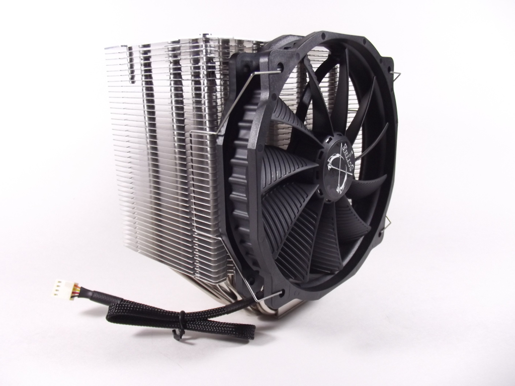
I am beginning to appreciate the wire fan mounting mechanism many manufacturers are using. It is easy to clip the fan onto the heatsink and just as easy to remove. It also allows for potential movement from heat expansion without undue strain on the mounting points. Checking the layout of the fan casing shows the fan wire mount is optimized for a 120mm case mounting points, so trying a standard 140mm fan would mean an unstable fan attachment. If you choose to mount a second fan for a push/pull setup, make sure it has a 120mm mount setup to ensure a secure attachment.
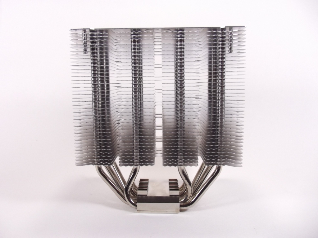
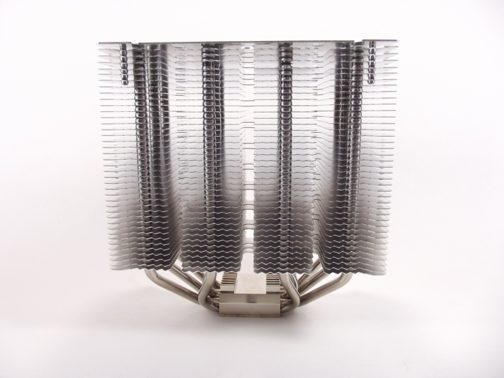
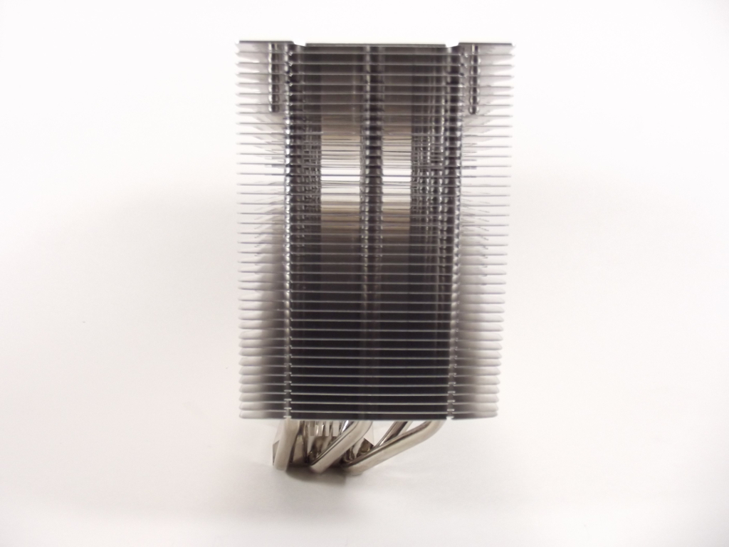
The front and rear view of the heat sink shows the even layout of the dissipation plates with a fairly consistent spacing of 2.6mm between the plates. If you noted what appear to be fins on the thermal pad, you are partially correct. They also provide the holding points for the mounting mechanism.
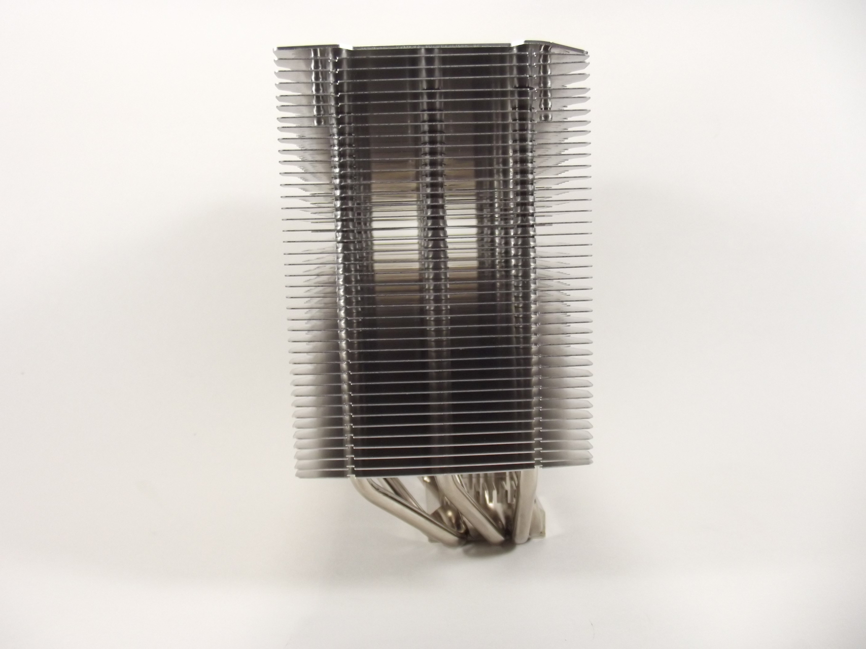
The side views shows the offset of the thermal pad to the heat sink pipes. Again we can see the consistent spacing of the plates along with a bent top cover from my own clumsy handling. Fortunately it's nothing I couldn't correct with small needle nose pliers (and a little finesse).
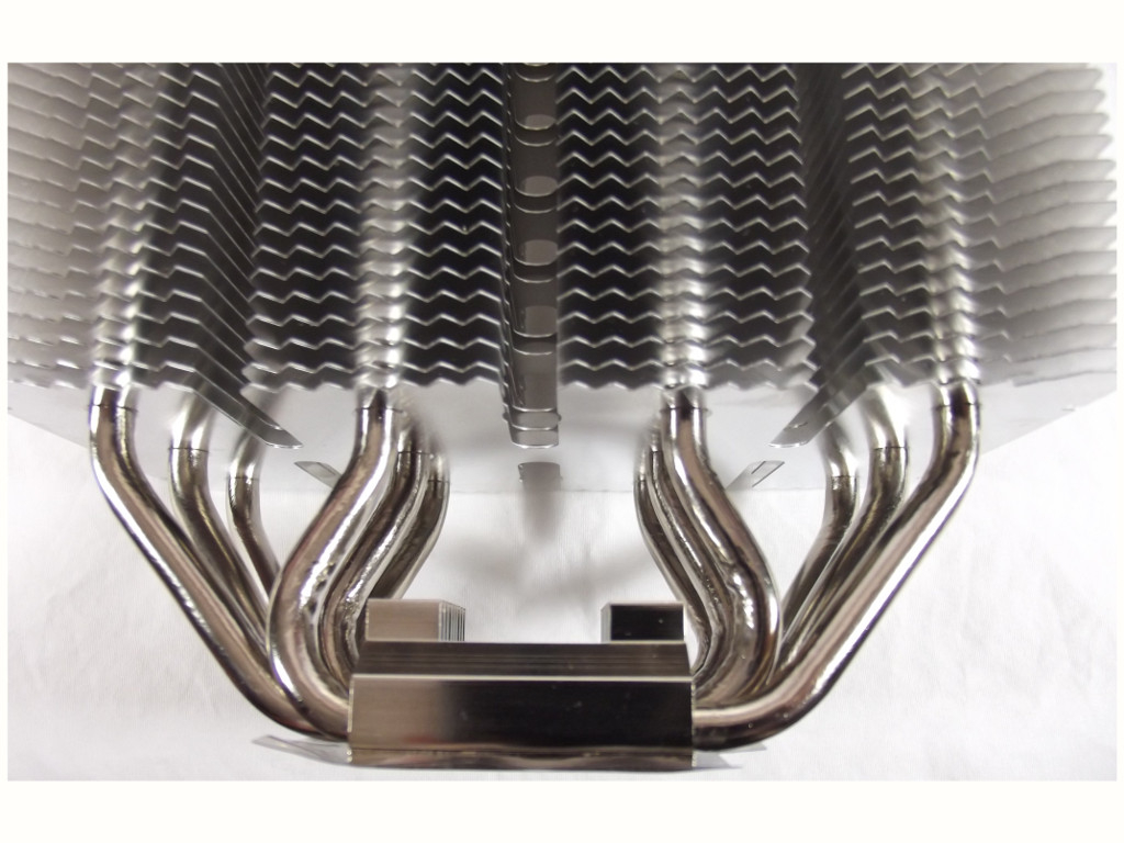
A close-up shot of the pipes leading into the dissipation plates show a very precise bending of the heat pipes to fit them into such a small hole in each plate. If you then take a close look at the second shot of the thermal pad, you can see the compression deflection of the heat pipes as they exit and bend upward to fit into their designated dissipation plate hole. You can also note that the pipes bending to fit into the inner plate holes have a greater amount of compression deflection. This is normal and should not deter from proper operation of the heat pipes.
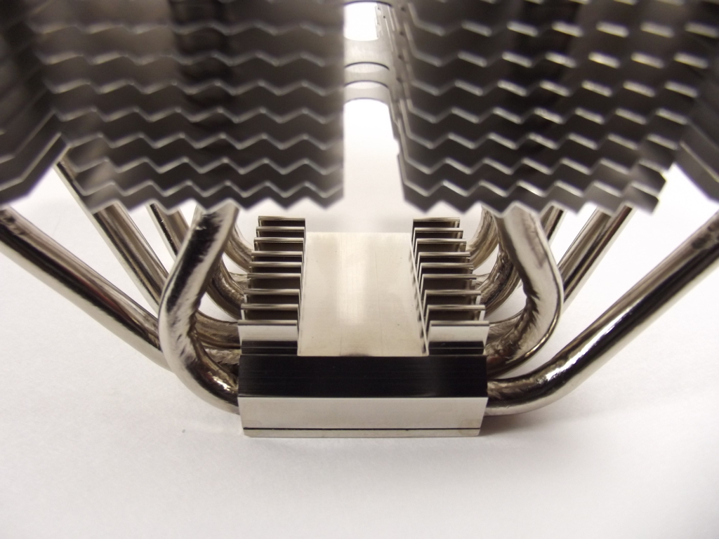
The bottom of the thermal pad shows a high degree of polishing, as seen in the following photo. Since the heat pipes don’t protrude through the top cover, I don’t see this being part of the heat dissipation aspect of the Mugen Max. It is probably just for aesthetics with their logo stamped into the plate along with four holes for the mounting pins and one hole you will learn more about about later in this review.


Moving on to the included fan we find the GlideStream 140 PWM model to deliver the actual air movement portion of the cooler. When Scythe increased the size of the heat sink, it also increased the size of the fan. Now we have a fan to move more air across those dissipation plates.
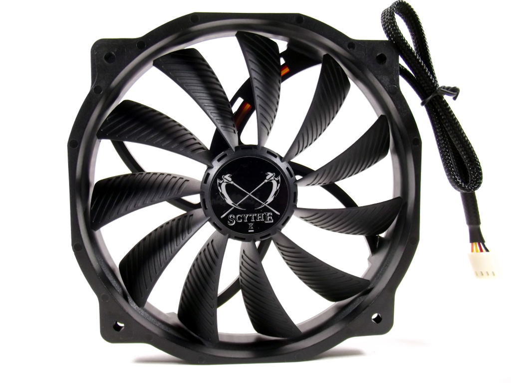
At the rear of the fan we find the hub braces are curved in the opposite direction of the air blades. This certainly keeps the blades from aligning with the hub braces and causing a dead spot in the air flow into the heat sink. Note the small center hub allowing for longer air blades and thus more air flow.

Looking at the air blades we see grooves on the front with a smooth back. These groves reduce the air resistance, therefore optimizing the air flow over the blade. I noticed how the blades are almost mounted to the hub at 90° but flare and widen as they turn into the air stream to push the air into (or out of, for dual fans) the heat sink dissipation plates.


Here is a close up of the mounting flanges of the case fan. Mounted in a 120mm pattern lessens the amount of material needed in the fan casing. Note also the ribbing of the outer fan shroud, further reducing the fan's weight without compromising structural integrity.

Article Index |
|