Engineers working on the Silvertown Tunnel have successfully rotated the first 1,400t section of the UK’s largest tunnel boring machine (TBM) 180° in the reception chamber using an innovative "nitrogen skate" system.
The Silvertown Tunnel is a new twin-bore road tunnel currently under construction beneath the River Thames between Silvertown and Greenwich. It is being delivered by Riverlinx CJV, a joint venture of Bam Nuttall, Ferrovial and SK Ecoplant, for Transport for London.
Most twin-bore tunnels either use two TBMs or dismantle the single TBM and return it to the initial launch point for its second drive. The site, time and financial constraints on the Silvertown Tunnel project meant that the team decided to devise a way to rotate the machine 180° and send it back under the river to bore the northbound 1.1km tunnel.
“This was the most efficient way of doing the two tunnels from a cost perspective and a programme perspective,” Riverlinx operations director Borja Trashorras said. “And in doing so, we’ve done it in the most innovative way that we could, in a way which has never been done before in the UK.”
TBMs have been rotated in a similar manner in Paris and Stuttgart, Trashorras explained, but in both cases it was just to make the extraction of the machines easier – not to bore another tunnel.
It has also never been done with a machine this large. The Silvertown Tunnel TBM is 82m long from cutterhead to the end of its backup gantries and the cutter head has a 12m diameter. The tunnelling shield alone is 19m long from cutter head to the rear of the screw conveyor and weighs 1,400t.

A rotation chamber was excavated at the point where the TBM breaks through from its southbound drive at Greenwich. The chamber is 18m deep from base slab to surface, 40m long from headwall to rear wall and 39m wide. The TBM will emerge into the chamber in four sections - the shield and the three backup gantries.
The shield was brought into the chamber first and onto a platform-like restraint system, which allowed it to maintain ring pressure at 40bar so that it could continue installing the concrete rings even as it was emerging. When the shield had fully emerged from the tunnel, it was separated from the adjoining gantry.
The TBM broke into the rotation chamber at a 4% gradient, rising from from the flat base of the tunnel beneath the river to the surface. The first stage in rotating it was to make sure it was level.
The first step to levelling the shield was moving the cutter head slightly out from the rest of the shield. “It’s very delicate this machine in terms of its centre of gravity,” explained Riverlinx project manager Ivor Thomas. As the cutter shield was edging its way out of the tunnel, a special hydraulic system for levelling it was put in place beneath it. A large steel band was put in place to catch the rear of the TBM shield as it emerged. The hydraulic rams were directly beneath this band and were then used to jack up the rear of the shield level with the front.
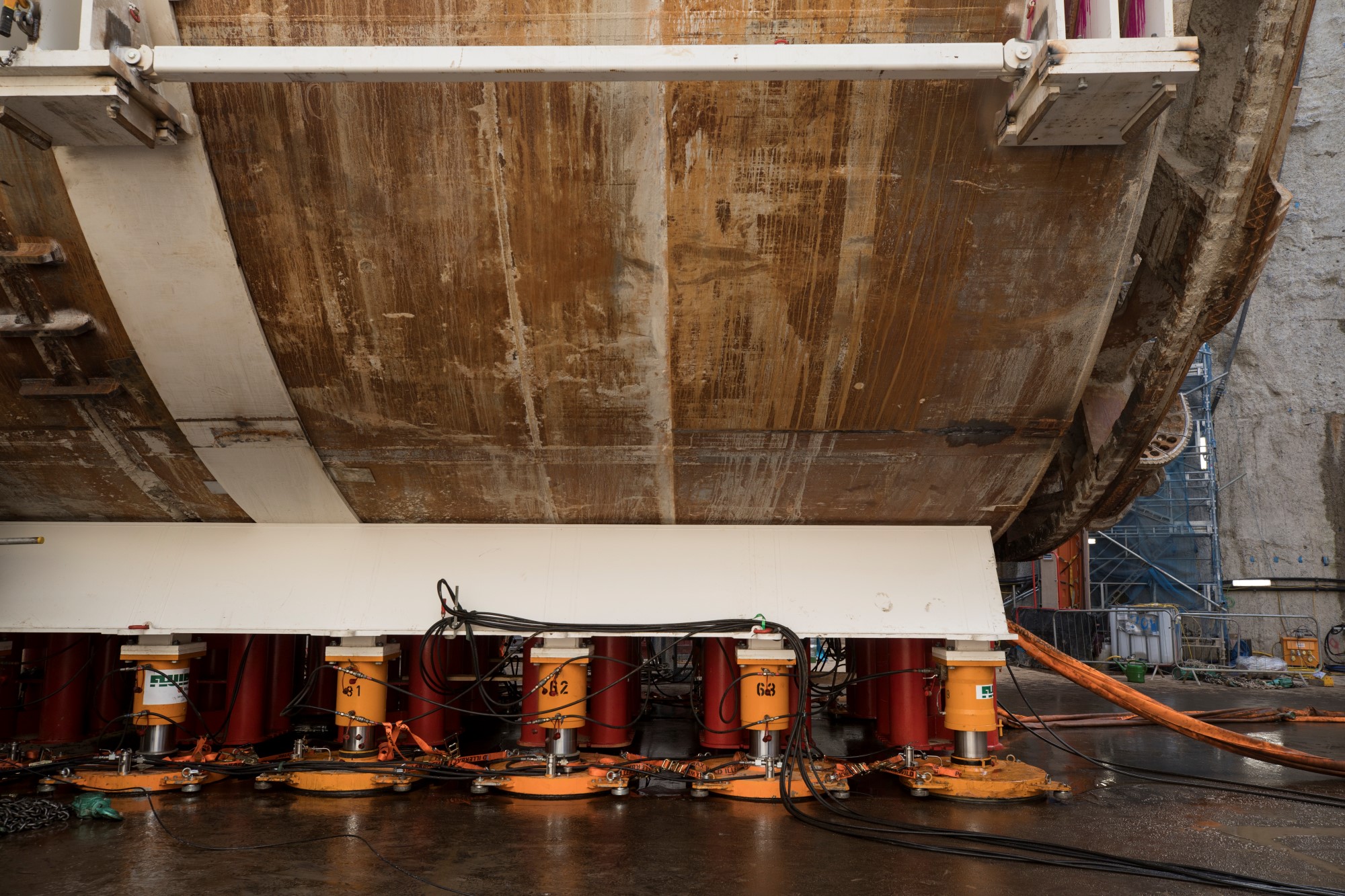
The cradle holding the TBM head, sitting atop the hydraulic jacks and nitrogen skate system
The next step saw a special steel cradle “floated” under the TBM shield on nitrogen skates, which are stationed all around the underside of the cradle. The nitrogen skates are a system of hydraulic feet sitting atop a layer of compressed nitrogen, which allows the cradle holding the machine to “skate” across the surface.
“Machines have been rotated on compressed air before, but to rotate a machine of this size on compressed air we’d probably have needed to hire all of the compressors in the UK,” Thomas said. “We used nitrogen because it’s commonly available, it’s inert, it’s not poisonous, it’s lighter than air – and you get a lot of bang for your buck. We were able to use a bank of 12 bottles of nitrogen for this system.”
The top of the system features stainless-steel hydraulic oil jacks at 350bar, which can be jacked up and down to do the fine levelling of the machine and ensure it’s truly horizontal. Below this are the skates, wide and flat circular feet with a rubber skirt, which have nitrogen pumped in through hoses and maintained at 250bar. When the cradle is ready to be moved, the hydraulic system is locked off and the skates move on a bubble of nitrogen. The floor of the rotation chamber is covered in a layer of 20mm thick steel plates that are grouted into position and then oiled to ease the movement of the skates.
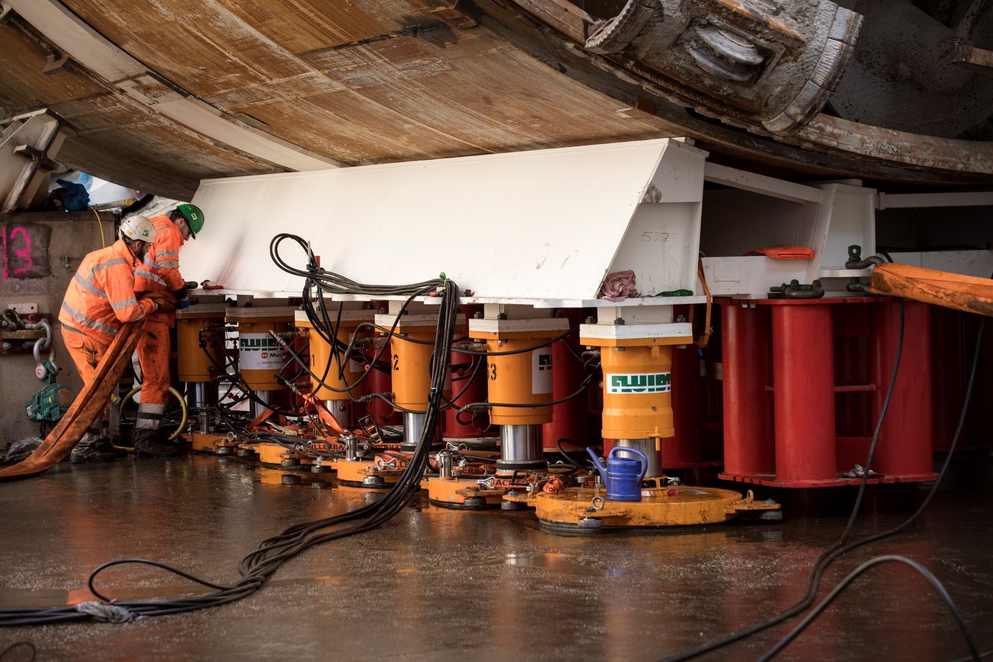
Engineers tending to the cradle, sitting on the nitrogen skate system
“We’re not lifting it; the nitrogen system is about breaking down the friction between the steel plate and the machine,” Thomas explained. “There is a skirt around the bottom of each skate and we pump in very small amounts of nitrogen. We oil the steel plates and break down the friction, allowing us to move 1,400t of machine.”
The movement is achieved by pulling it with remote controlled 25t air winches that are anchored to the walls of the rotation chamber. The shield was pulled away from the tunnel portal, then pulled sideways to make two “handbrake turns”, before being aligned with the tunnel eye for the second bore. “It’s like a big hovercraft,” Thomas said. The rotation and movement from one side of the chamber to the other took a day.

The cradle attached to the 25t air winch, atop the nitrogen skate system
The same process will be repeated with the first gantry in April. The gantry is lighter than the shield head, but longer. “In terms of space, gantry one is probably the most difficult to do,” Trashorras said. “But in terms of key principles, the rotation is exactly the same; we’ll put the cradle underneath it and pull it with the pulley system that’s anchored to the wall.”
Once rotated, the first gantry will be reattached to the cutter shield and the TBM will commence what is known as the umbilical launch, which should start by the end of April. The part-TBM will start on the second bore, reaching around 70m into the drive. Meanwhile, the second and third gantries will be brought into the chamber, rotated and attached. Once the full length of the TBM is reconnected, the digging can enter “full mode”. It is hoped that this can be achieved by the end of June.
With the TBM completely out of the southbound tunnel, the spoil conveyor can be put in place. This belt will take spoil from the TBM back down the northbound tunnel, do a U-turn in the rotation chamber and take the it back through the southbound tunnel to Silvertown. From there, it will be removed from site via barge.
The rotation of the TBM for the Silvertown Tunnel is likely to become a pathfinder process for other projects necessitating a twin bore, Trashorras said. “Other clients are now considering this as a potential for future projects where they’re trying to do it as efficiently as possible and trying to meet other agendas such as cost, carbon footprint or reduced materials,” he said. “I can’t disclose which clients, but people are very keen to understand whether this was a success and whether it can be showcased anywhere else in the UK.”
Like what you've read? To receive New Civil Engineer's daily and weekly newsletters click here.
Have your say
or a new account to join the discussion.