This story begins with a 4WD 1998 Honda Passport equipped with a 3.2 V6 engine and 4L30E transmission. The shift indicator in the cluster was not functioning correctly and transmission was shifting hard. The shift indicator showed ‘P’ in Park, and ‘1’ in D3, D2, or D1. The indicator didn’t light up in any other gear. It seemed like a straightforward diagnosis since the mode switch (range sensor) has a high failure rate on these vehicles. However, a new OEM mode switch from Honda had been previously installed for this issue with no change, so it was time to start the real work of accurately diagnosing the cause. Little did I know that this project would become “The Nightmare on Oak Street.”
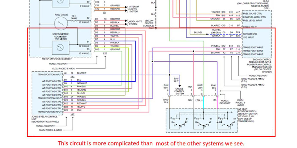
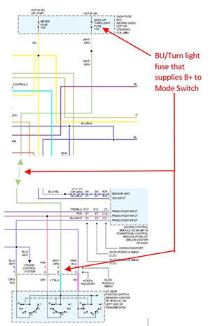
There was no data stream available to view on this vehicle using our trusty Snap-On MT2500 scanner, so some pinpoint testing was the next order of business. To start, I printed out the wire diagrams and familiarized myself with the component and connector locations. This system is a little more complex than others. The mode switch sends information to the PCM as well as the Alarm and Relay Control Unit (ARCU, a.k.a. Multiplex Control Unit). The PCM uses this information to regulate the transmission operation, and the ARCU sends the information to the IP cluster. (See Figure 1).
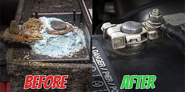
First things first: I cleaned the science experiment at the battery terminals. (See Figure 2).
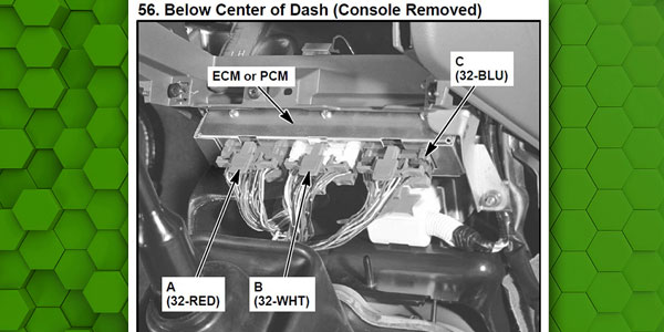
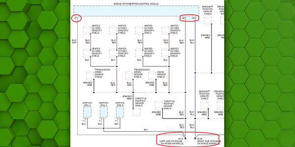
I then went on to check the power and ground circuits. How many times have I skipped these steps, only to get bitten by them later? The PCM was below the center of the dash, under the console. (See Figure 3).
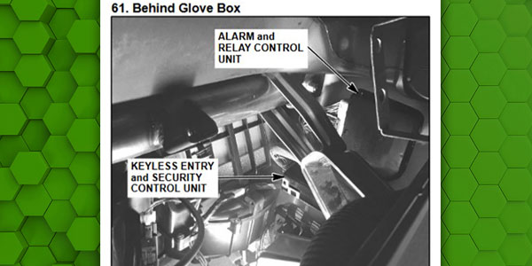
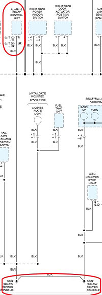
The Alarm and Relay Control Unit was above right kick panel (it was hidden). See Figure 4.
I gained access to both modules for circuit checks. Power is needed at both the Mode Switch and the ARCU (See Figure 5).
Now that I had access for testing, it was time to break out the DVOM. The backup lamps and turn signals worked, which meant that the fuse (shared by the Mode Switch and ARCU) was good. I checked for B+ at the Mode Switch. There was B+ to the Mode Switch, ignition and the ARCU. I checked the ground circuit from the battery to the PCM and the ARCU to. At this point, all that I tested was working well. (See Figures 6 and 7).
With the voltage supply and grounds testing good, it was time to see if I was getting signals from the Mode Switch to the PCM and ARCU. The Mode Switch has four internal switches. Power is supplied to the switch on pin 8, and as the lever is moved it directs power through the internal switches to their assigned circuits, as follows:
- Pin 8 (light blue): B+ from the backup/turn signal fuse.
- Pin 2 (white): effective in P, N, 3, L
- Pin 5 (purple): effective in P, R, 3, 2
- Pin 6 (gray): effective in R, N, D, 3
- Pin 7 (orange/black): effective in D, 3, 2, L
When testing each pin, there should be continuity in its respective ranges. I also tested the voltage from the Mode Switch at the PCM and ARCU with them disconnected. Pins 5, 7 and 2 tested okay. Pin 6 tested open in all ranges. Bingo!
It appeared that I had found the problem. Could there be two Mode Switches with the same problem? Remember, this vehicle arrived to us with a new, OEM Mode Switch installed. Could this new switch be bad?
We purchased a new mode switch and installed it on the vehicle. Now the indicator was functioning correctly, and the shifts were normal. We always perform a final road test before the vehicle is delivered to the owner. For the first seven miles all was well, then as I turned down the home stretch, the indicator went blank, and the transmission wouldn’t shift. What happened? Everything was working so well up to that point.
I limped it back to the shop and ran the lever through the ranges. I witnessed the same exact problem as before. What did I miss?
Read more stories in our R&R Tech series here.
I ran through the tests again. Again, open on pin 6. What’s going on? I took the mode switch apart and there it was: a piece of the thin metal used on the circuit board to make the slide connection was missing. The only thing that I could think was that there had to be too many amps on that circuit, which were burning up the circuit on the board.
I used a fused jumper (5-amp fuse) with an ammeter in-line to test the load on pins 5, 6 and 7. Pins 5 and 7 had .012-amp draw. But pin 6 blew my 5-amp in-line fuse. I disconnected the ARCU and replaced the fuse. I blew the fuse again. I disconnected the PCM, and it blew that fuse. It seemed to indicate that I had a short to ground somewhere.
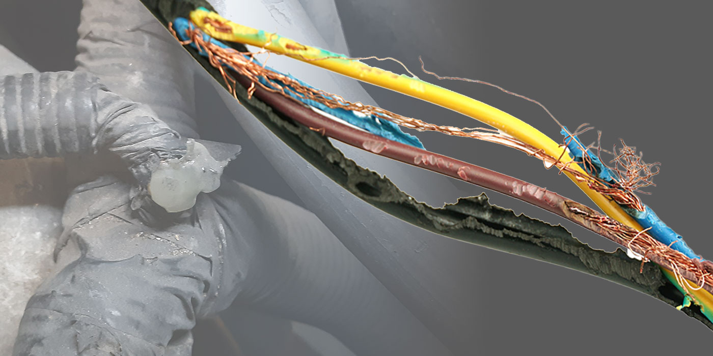
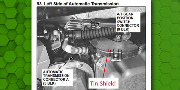
I started the hunt at the Mode Switch. The wiring harness passes by the lower left side of the bellhousing with a shield to protect the harness. I removed the shield and there it was: a shiny piece of copper staring at me. The shield had rubbed through the conduit, tape and finally the insulation, causing the short. (See Figure 8).
I repaired the wire, taped the harness and installed a new piece of conduit. At the same time, I bent the shield so there were no sharp edges to wear through again. I retested the circuit and installed a new Mode Switch, and this time it passed the 15-mile final road test.
Moving the harness around during the Mode Switch replacement must have been enough to move the bare wire away from the shield for a time. Then after driving, the vibrations moved it back to its original resting place and shorted to ground, repeating the fault.
When I took the Mode Switch off and took it apart, I could only conclude that the printed circuit was acting as a fuse, but the only problem was that it failed with a lot less amperage than what the fuse that powers the circuit is rated for. In the end, the root cause was found, and the issue corrected. The customer was pleased and that’s always what matters the most.
Randy Peterson has worked for Certified Transmission for more than twenty-five years and is an ASE Certified Master Technician, including L-1.