Pulse Width Modulation (PWM), an effective technology that uses the digital output of a microprocessor to control analog circuits. It is widely used from measurement to communications in the fields of power control and conversion, especially in the field of inverters for home solar power system. This article will take you into the world of PWM and understand what is PWM.
Main content:
1. What is PWM
To understand what is PWM, we first need to understand the following PWM parameters:
- PWM frequency:
It refers to the number of times the signal goes from high electrical level to low electrical level and back to high electrical level within 1 second (one cycle), that is to say, how many cycles of PWM are there in one second.
Unit: Hz
Expression: 50Hz, 100Hz
- PWM period:
T=1/f period=1/frequency
50Hz = 20ms each cycle
If the frequency is 50Hz, that is to say, one cycle takes 20ms, so there are 50 PWM cycles in one second.
- Duty cycle:
It is the ratio of the time of high electrical level to the entire cycle time in a pulse cycle.
Unit: % (0%-100%)
Expression: 20%
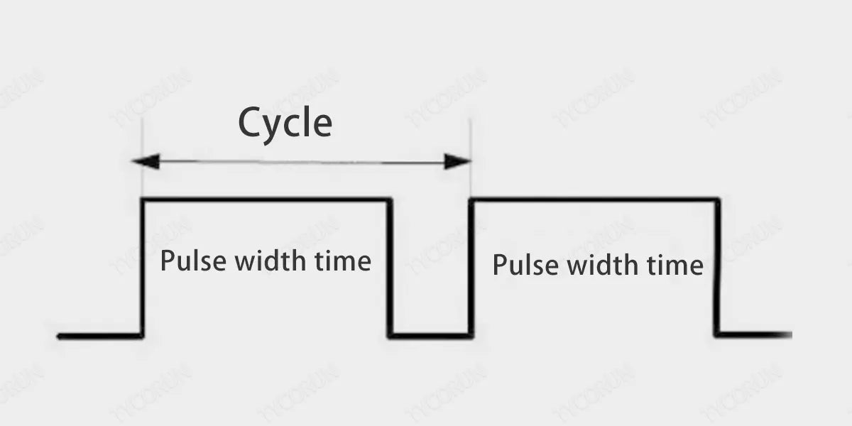
- Cycle:
The time of one pulse signal The number of test cycles within 1 second is equal to the frequency.
- Pulse width time:
High electrical level time. The ratio of the pulse width time to the total cycle time is the duty cycle. For example, if the cycle time is 10ms and the pulse width time is 8ms, then the low electrical level time is 2ms and the total duty cycle is 8/8+2= 80%.
By adjusting the duty cycle, the pulse width time can be adjusted, and the frequency is the number of pulse signals per unit time. Taking the 20Hz duty cycle of 80% as an example, it means that 20 pulse signals are output within 1 second, and the high electrical level time of each time is 40ms.
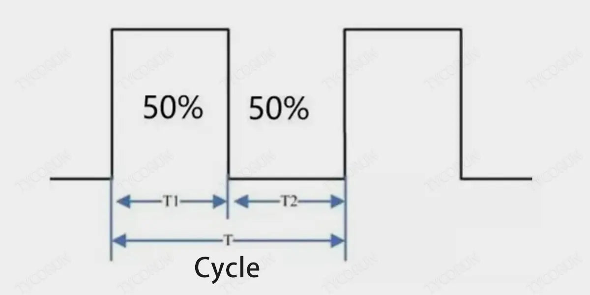
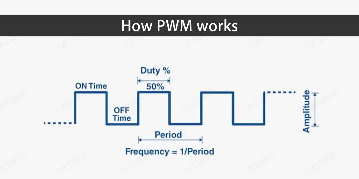
In the figure above, the period is T, T1 is the high electrical level time, and T2 is the low electrical level time. Assume that the period T is 1s, then the frequency is 1Hz, then the high electrical level time is 0.5s, and the low electrical level time is 0.5s. The total duty cycle is 0.5 /1 =50%.
2. How PWM works
After understanding what is PWM, let’s figure out how it works. Take a microcontroller as an example. The IO port of the microcontroller outputs a digital signal. The IO port can only output high electrical level and low electrical level.
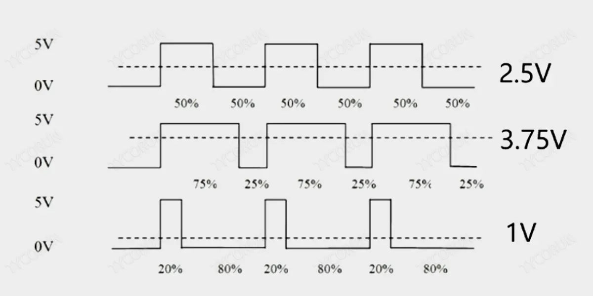
Assume that the high electrical level is 5V and the low electrical level is 0V. Then we need to output different analog voltages. What is PWM doing is used to obtain an analog voltage signal simulated using a digital signal by changing the duty cycle of the square wave output from the IO port.
The voltage is clamped to the simulated load (such as LED lights, DC motors, etc.) in a repetitive pulse sequence of connecting 1 or disconnecting 0. Connection is the DC power supply output, and disconnection is the DC power supply disconnection. By controlling the connection and disconnection time, in theory, any analog voltage that is not greater than the maximum voltage value (that is, any size between 0 and 5V) can be out put.
For example, if the duty cycle is 50%, that means half of the high-electrical level time and half of the low-electrical level time. At a certain frequency, you can get a simulated 2.5V output voltage. Then the voltage obtained with a 75% duty cycle is 3.75V.
The adjustment effect of what is PWM doing comes from controlling the width of the "occupancy period". As the occupancy period becomes wider, the output energy will increase. The average voltage value obtained through the resistance-capacitance conversion circuit will also increase, and the occupancy period will become shorter. The average voltage of the output voltage signal will decrease, and the average voltage value obtained through the resistance-capacitance conversion circuit will also decrease.
That is, at a certain frequency, different output analog voltages can be obtained through different duty cycles, this is also the principle that makes what is PWM doing to achieve D/A conversion. What is PWM doing is to change the effective output voltage by changing the duty cycle in one cycle at a suitable signal frequency.
The greater the PWM frequency, the faster the response. So, what is PWM signal? Let’s take the frequently used breathing lamp as an example: Most people’s eyes have no flickering sensation at refresh rates above 80Hz. When the frequency is very high, no flickering is visible, and the larger the duty cycle, the brighter the LED. When the frequency is very low, flickering is visible, and the larger the duty cycle, the brighter the LED.
Therefore, at a fixed frequency, the brightness of the LED light can be changed with different duty cycles.
3. PWM control of motor speed
What is PWM control of motor speed? The duty cycle can be used to adjust the motor speed. The duty cycle is the ratio of high electrical level in one cycle. The greater the ratio of high electrical level, the greater the duty cycle. For DC motors, The motor can rotate when the output pin of the motor is at a high electrical level. When the output is at a high electrical level, the motor will rotate, but the speed is increased bit by bit.
When the high electrical level suddenly turns to a low electrical level, the motor prevents the current due to the inductance. The effect of mutation will not stop and will maintain the original speed.
In this way, the speed of the motor is the average voltage value output during the cycle, so in essence, the speed regulation is to put the motor in a state where it seems to be stopped but not stopped, and it seems to be rotating at full speed but not at full speed. Then the average value in a cycle is the speed adjusted by duty cycle.
In motor control, the greater the voltage, the faster the motor speed. By outputting different analog voltages through PWM, the motor can reach different output speeds. Of course, in motor control, different motors have their own adapted frequencies.
If the frequency is too low, the movement will be unstable. If the frequency is just within the hearing range of the human ear, sometimes a whistling sound will be heard. A motor with too high a frequency may not be able to respond. The normal motor frequency is between 6-16kHz.
4. PWM control of steering gear
What is PWM control of steering gear? The control of the servo is to control the different steering angles of the servo through a fixed frequency and different duty cycles. The frequency of the servo is generally 50HZ, which is a time base pulse of about 20ms, and the high level part is generally in the range of 0.5ms-2.5ms.
To control different steering angles, the PWM high-level part of 500-2500us corresponds to controlling 0-180 degrees of the 180-degree servo.
Taking the 180-degree angle servo as an example, the corresponding control relationship is as follows:
0.5ms - 0°
1.0ms - 45°
1.5ms - 90°
2.0ms - 135°
2.5ms - 180°

5. Advantages of PWM for inverters
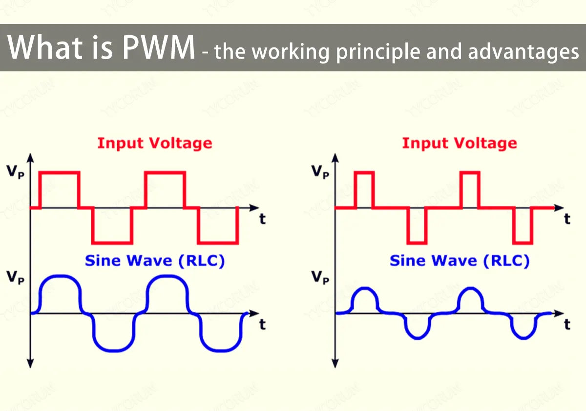
What is PWM technology of the inverter is a reference wave called the "modulating wave", and a positive triangle wave with N times the frequency of the modulating wave is called the "carrier wave".
Since the up and down width of the positive triangle wave or sawtooth wave is a linearly changing waveform, when it intersects with the modulation wave, a set of rectangular pulse sequences with equal amplitude and width proportional to the value of the modulation wave function can be obtained for equivalent modulation.
What is PWM doing is to use switching quantities to replace analog quantities, and convert DC power into AC power by controlling the on and off switching tubes of the inverter, such as 2000 watt inverter pure sine wave and 3000 watt solar inverter.
When the modulation wave is a sine wave, the pulse width of the output rectangular pulse sequence changes according to the law of the sine function. This modulation technology is usually also called sine wave pulse width modulation technology.
What is PWM technology can be divided into three major categories, namely waveform modulation PWM technology, optimized PWM technology and random PWM technology. What is PWM technology used in can be both voltage-type inverters and current-type inverters that work with LFP battery. It has played a great role in promoting the development of inverter technology.
Compared with the multiple superposition method, PWM has the following advantages:
- The circuit is simple, and only one power control stage can adjust both the output voltage and the output frequency.
- An uncontrollable rectifier bridge can be used to make the power factor of the system to the grid independent of the inverter output voltage value.
- Frequency regulation and voltage regulation can be performed at the same time, regardless of the component parameters of the intermediate DC link, and the system has a fast dynamic response speed.
- Better waveform improvement effect can be achieved.
Related posts: UPS vs inverter, home solar inverter, solar microinverter