Small Magnetic Loop Antenna Project - QRPBuilder.com
Small Magnetic Loop Antenna Project - QRPBuilder.com
Small Magnetic Loop Antenna Project - QRPBuilder.com

You also want an ePaper? Increase the reach of your titles
YUMPU automatically turns print PDFs into web optimized ePapers that Google loves.
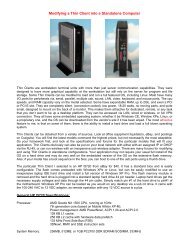
WA4MNT <strong>Small</strong> Transmitting <strong>Magnetic</strong> <strong>Loop</strong> <strong>Antenna</strong> <strong>Project</strong><br />
30m, 20m, 17m, 15m, 12m, 10m Bands<br />
With the solar cycle improving, I wanted to build an efficient HF antenna for the upper bands that I<br />
could easily throw in the trunk of the car and operate quickly with a minimum of setup time. I<br />
decided on a small magnetic loop antenna after researching the subject on the web and reading the<br />
following statement from VK5KLT’s article on small magnetic loop antennas.<br />
“A properly designed and constructed small loop of nominal 1m diameter will<br />
outperform any antenna type except a tri-band beam on the 10m/15m/20m bands,<br />
and will be within an S-unit (6db) or so of an optimised mono-band 3-element<br />
beam that’s mounted at an appropriate height above ground.”<br />
There is a wealth of information on small magnetic loop antenna construction on the web. One of<br />
the best sources I found was by AA5TB, http://www.aa5tb.<strong>com</strong>/loop.html, and VK5KLT,<br />
http://www.brisdance.<strong>com</strong>/vk4amz/files/Download/UnderMag<strong>Loop</strong>.pdf . The antenna I built is a<br />
<strong>com</strong>pilation of ideas I borrowed from many sources, gleaned from the work of others, and a little<br />
redesign.
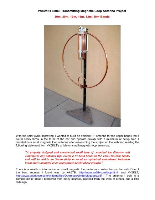
This project resulted in a three foot diameter copper loop mounted on a small pedestal, with<br />
continuous coverage of 30m through 10m bands (10MHz-30MHz). I have been able to obtain an<br />
SWR of 1:1 - 1.2:1 over the entire range. Based on the advice of the most successful builders, I<br />
chose copper as the metal of choice and all joints are silver soldered to reduce the interconnection<br />
resistance. I chose to design my own trombone style capacitor (~10pF - ~110pF), and shielded<br />
Faraday <strong>Loop</strong> input. I used copper tubing, readily available low loss dielectric materials, PEX (cross<br />
linked polyethylene) tubing for the capacitor insulator, UHMW plastic (Polypropylene) for all other<br />
RF exposed parts, and non magnetic hardware for all mechanical fastening. My design was based<br />
on AA5TB’s on-line calculator, http://www.aa5tb.<strong>com</strong>/aa5tb_loop_v1.22a.xls, and my dielectric<br />
spacing exceeds a 2KW rating. I chose to mount my portable loop, a little less than one diameter,<br />
off the ground, from the bottom of the loop, with six radials, two loop diameters long, from the base.<br />
These antennas are high-Q resonant circuits. Many kilovolts can be present across<br />
the capacitor, and produce concentrated electro-magnetic radiation even at low<br />
power levels. For safety, maintain a minimum of 6 feet away from the antenna, while<br />
transmitting.<br />
I have access to milling and lathe equipment, so my exact approach may not be suitable for many<br />
amateurs; however many good designs are available using butterfly or vacuum capacitors and<br />
easier available tools. Even simpler monoband designs may be more appropriate. I incorporated a<br />
motor drive for remote tuning with a wired control cable. With the antenna bandwidth being so<br />
narrow, tuning for maximum receiver noise yields almost optimum SWR. I use no antenna tuner<br />
between the radio and antenna.<br />
I am not an antenna theoretician; my expertise is in mechanical design. I have attached all my<br />
detailed .pdf’s and defer to the <strong>com</strong>plete VK5KLT “An Overview of the Underestimated <strong>Magnetic</strong><br />
<strong>Loop</strong> HF <strong>Antenna</strong>” article at the end of this document for the theory of operation.<br />
Results using my MFJ-259B antenna analyzer:<br />
10m - 28.700 SWR 1.2 : 1 R=53, X=10<br />
28.200 SWR 1.1 : 1 R=46, X=8<br />
12m – 24.900 SWR 1.2 : 1 R=56, X=9<br />
15m – 21.300 SWR 1 : 1 R=47, x=0<br />
21.060 SWR 1 : 1 R=43, X=0<br />
17m – 18.150 SWR 1.2 : 1 R=43, X=7<br />
20m – 14.250 SWR 1.1 : 1 R=43, X=0<br />
14.060 SWR 1.1 : 1 R=44, X=0<br />
30m – 10.125 SWR 1.1 : 1 R=50, X=8<br />
<strong>Small</strong> magnetic loops typically have 5 dBi gain when used with two loop diameter length radials.<br />
They exhibit a vertically polarized signal at the horizon and horizontally polarized signal overhead.<br />
Thank you to all the amateurs that have shared their wisdom and made the information public on<br />
the internet to make this project a success.<br />
You may consider joining the Yahoo groups, <strong>Magnetic</strong><strong>Loop</strong><strong>Antenna</strong> or Mag<strong>Loop</strong><br />
Ken - WA4MNT<br />
www.qrpbuilder.<strong>com</strong><br />
E-mail – kloc@swiftwireless.<strong>com</strong>
Trombone style capacitor ~10pF – ~110pF<br />
Shielded Faraday input loop
Trombone capacitor gear drive<br />
Using a www.mpja.<strong>com</strong>, #16816MD, 24 vdc, 40 rpm gearmotor<br />
Frequency scale
Base with thumbscrews for 6’ radials, and surplus fiberglass mast section.<br />
Motor controller and cables 12v gel cell transceiver supply,<br />
with 12v to 24v switching supply<br />
DC-DC module, www.lightobject.<strong>com</strong><br />
for the gearmotor drive
Set up for operation<br />
<strong>Small</strong> enough to fit in the trunk of my Toyota Corolla
12v -24v switcher for gearmotor<br />
Motor controller, direction and speed<br />
www.mpja.<strong>com</strong>, #16816MD, 24v, 40 rpm gearmotor
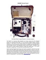
Common Plastics Dissipation Factor Chart<br />
This will aid you in selecting suitable plastics for loop construction. Look for plastics with low dissipation<br />
factors. G10 /G11 glass epoxy board have a poor dissipation factor, 0.018, similar to PVC. UHMW<br />
(Polypropylene) is one tenth the cost of PTFE (Teflon).
D<br />
C<br />
B<br />
A<br />
2<br />
1 3 4 7 8<br />
5<br />
SEE DETAIL B<br />
TROMBONE STYLE<br />
CAPACITOR<br />
`15pF - 80pF<br />
SEE DETAIL C<br />
SEE DETAIL D<br />
SEE DETAIL A<br />
1.825" O.D. FIBERGLASS MAST SECTION<br />
(MILITARY SURPLUS)<br />
ALUMINUM BASE PLATE<br />
2<br />
CAUTION !!!<br />
1 3 4 7 8<br />
5<br />
REV<br />
ECO<br />
6<br />
DIMENSIONS - INCHES<br />
UNLESS SPECIFIED<br />
TOLERANCES ARE:<br />
ANG. # 0.5<br />
X # 0.25<br />
X.X # 0.1<br />
X.XX # 0.01<br />
X.XXX # 0.001<br />
6<br />
INITIAL RELEASE<br />
THE INFORMATION CONTAINED IN THIS<br />
DOCUMENT IS THE PROPERTY OF<br />
BENT RIVER MACHINE AND SHALL NOT BE USED<br />
OR DISCLOSED OUTSIDE OF BENT RIVER MACHINE<br />
WITHOUT WRITTEN AUTHORIZATION<br />
ENG: WA4MNT<br />
DO NOT SCALE<br />
SCALE: 0.048<br />
3RD ANG<br />
PROJECT<br />
TITLE<br />
DESCRIPTION<br />
THESE ANTENNAS ARE HIGH-Q RESONANT CIRCUITS.<br />
MANY KILOVOLTS CAN BE PRESENT ACROSS THE CAPACITOR,<br />
AND PRODUCE CONCENTRATED ELECTRO-MAGNETIC<br />
RADAITION EVEN AT LOW POWER LEVELS. FOR SAFETY,<br />
MAINTAIN A MINIMUM OF 6' AWAY FROM THE ANTENNA<br />
WHILE TRANSMITTING.<br />
NOTES:<br />
ALL COPPER ANTENNA ELEMENTS JOINED BY SILVER SOLDER<br />
ANY FASTENERS USED MUST BE 300 SERIES S.S.<br />
OPTIMUM HEIGHT IS TWO LOOP DIAMETERS ABOVE GROUND<br />
OPTIMUM RADIALS ARE ~2 LOOP DIAMETERS LONG<br />
FORMAT - B<br />
SHEET 1 OF 3<br />
WA4MNT 3' SMALL MAGNETIC<br />
LOOP ANTENNA 30m-10m<br />
DWG. NO.<br />
WA4MNT<br />
P.O. BOX 956<br />
CLARKDALE, AZ 86324<br />
928-639-3481 (VOICE)<br />
WWW.QRPBUILDER.COM<br />
LOOP_ASSY<br />
DATE<br />
08/08/10<br />
BY<br />
KL<br />
REV<br />
D<br />
C<br />
B<br />
A
D<br />
C<br />
B<br />
A<br />
POINTER<br />
2<br />
1 3 4 7 8<br />
5<br />
2EA. STATOR SPACER<br />
DETAIL B<br />
SCALE 0.750<br />
2<br />
2 EA. MCM 7297K15 BEVEL GEARS & 2EA.<br />
.093 X .62 L. SS ROLL PINS<br />
ROTATION INDICATOR<br />
SHAFT<br />
SUPPORT<br />
2EA. ADJUSTMENT<br />
SPACER<br />
ANTENNA RING<br />
4EA. STATOR<br />
INSULATOR<br />
LOWER STATOR<br />
SUPPORT<br />
GEARSHAFT<br />
1 3 4 7 8<br />
5<br />
REV<br />
ECO<br />
6<br />
DETAIL A<br />
SCALE 0.750<br />
DIMENSIONS - INCHES<br />
UNLESS SPECIFIED<br />
TOLERANCES ARE:<br />
ANG. # 0.5<br />
X # 0.25<br />
X.X # 0.1<br />
X.XX # 0.01<br />
X.XXX # 0.001<br />
6<br />
INITIAL RELEASE<br />
THE INFORMATION CONTAINED IN THIS<br />
DOCUMENT IS THE PROPERTY OF<br />
BENT RIVER MACHINE AND SHALL NOT BE USED<br />
OR DISCLOSED OUTSIDE OF BENT RIVER MACHINE<br />
WITHOUT WRITTEN AUTHORIZATION<br />
ENG: WA4MNT<br />
DO NOT SCALE<br />
SCALE: 0.048<br />
3RD ANG<br />
PROJECT<br />
TITLE<br />
DESCRIPTION<br />
FORMAT - B<br />
SHEET 2 OF 3<br />
WA4MNT 3' SMALL MAGNETIC<br />
LOOP ANTENNA 30m-10m<br />
DWG. NO.<br />
WA4MNT<br />
P.O. BOX 956<br />
CLARKDALE, AZ 86324<br />
928-639-3481 (VOICE)<br />
WWW.QRPBUILDER.COM<br />
LOOP_ASSY<br />
DATE<br />
08/08/10<br />
WWW.MPJA.COM<br />
MOTOR #16816 MD<br />
12 VDC, 40 RPM<br />
BY<br />
KL<br />
MOTOR MOUNT<br />
ADJUSTMENT<br />
PLATE<br />
CONNECTOR<br />
BRACKET<br />
GEARSHAFT<br />
SPACER &<br />
SHORT<br />
GEARSHAFT<br />
UPPER STATOR<br />
SUPPORT<br />
2EA. STATOR<br />
ASSEMBLY<br />
2EA. STATOR<br />
SPACER<br />
REV<br />
D<br />
C<br />
B<br />
A
D<br />
C<br />
B<br />
FARADAY LOOP<br />
ASSEMBLY<br />
A<br />
2<br />
1 3 4 7 8<br />
5<br />
SO-239<br />
INPUT FLANGE<br />
2<br />
DETAIL D<br />
SCALE 0.500<br />
1 3 4 7 8<br />
5<br />
REV<br />
SCALE<br />
ROTOR ASSEMBLY<br />
SILVER SOLDER THE INPUT FLANGE TO<br />
THE ANTENNA RING ON THE BACKSIDE<br />
RING SUPPORT<br />
ANTENNA RING<br />
ECO<br />
6<br />
NUT<br />
DIMENSIONS - INCHES<br />
UNLESS SPECIFIED<br />
TOLERANCES ARE:<br />
ANG. # 0.5<br />
X # 0.25<br />
X.X # 0.1<br />
X.XX # 0.01<br />
X.XXX # 0.001<br />
6<br />
INITIAL RELEASE<br />
SCALE<br />
SPACER<br />
LEADSCREW<br />
THE INFORMATION CONTAINED IN THIS<br />
DOCUMENT IS THE PROPERTY OF<br />
BENT RIVER MACHINE AND SHALL NOT BE USED<br />
OR DISCLOSED OUTSIDE OF BENT RIVER MACHINE<br />
WITHOUT WRITTEN AUTHORIZATION<br />
ENG: WA4MNT<br />
DO NOT SCALE<br />
SCALE: 0.048<br />
3RD ANG<br />
PROJECT<br />
TITLE<br />
DESCRIPTION<br />
DETAIL C<br />
SCALE 0.750<br />
FORMAT - B<br />
SHEET 3 OF 3<br />
WA4MNT 3' SMALL MAGNETIC<br />
LOOP ANTENNA 30m-10m<br />
DWG. NO.<br />
WA4MNT<br />
P.O. BOX 956<br />
CLARKDALE, AZ 86324<br />
928-639-3481 (VOICE)<br />
WWW.QRPBUILDER.COM<br />
LOOP_ASSY<br />
DATE<br />
08/08/10<br />
BY<br />
KL<br />
REV<br />
D<br />
C<br />
B<br />
A
D<br />
C<br />
B<br />
A<br />
2<br />
1 3 4 7 8<br />
5<br />
SILVER SOLDER AND DRILL PLUG TO ACCEPT<br />
RG-8 CENTER CONDUCTOR, SOLDER CENTER<br />
CONDUCTOR TO PLUG<br />
SILVER SOLDER BOTH PLATES TO SHELL<br />
2<br />
.50 REF.<br />
SCALE<br />
1.000<br />
INSIDE CONDUCTOR AND<br />
INSULATOR OF RG-8 COAX<br />
SLIP FIT INTO SHELL<br />
AT FINAL ASSEMBLY SOLDER RG-8 CENTER<br />
CONDUCTOR TO CENTER OF SO-239 CONNECTOR<br />
1.00 REF.<br />
.72<br />
1 3 4 7 8<br />
5<br />
REV<br />
FARADAY FLANGE<br />
ECO<br />
DIMENSIONS - INCHES<br />
UNLESS SPECIFIED<br />
TOLERANCES ARE:<br />
6<br />
ANG. ± 0.5 °<br />
X ± 0.25<br />
X.X ± 0.1<br />
X.XX ± 0.01<br />
X.XXX ± 0.001<br />
6<br />
INITIAL RELEASE<br />
FARADAY SHELL<br />
ENG: WA4MNT<br />
DO NOT SCALE<br />
SCALE: 0.500<br />
3RD ANG<br />
PROJECT<br />
TITLE<br />
DESCRIPTION<br />
THE INFORMATION CONTAINED IN THIS<br />
DOCUMENT IS THE PROPERTY OF<br />
BENT RIVER MACHINE AND SHALL NOT BE USED<br />
OR DISCLOSED OUTSIDE OF BENT RIVER MACHINE<br />
WITHOUT WRITTEN AUTHORIZATION<br />
FORMAT - B<br />
SHEET 1 OF 1<br />
DWG. NO.<br />
WA4MNT<br />
P.O. BOX 956<br />
CLARKDALE, AZ 86324<br />
928-639-3481 (VOICE)<br />
WWW.QRPBUILDER.COM<br />
FARADAY_LOOP<br />
DATE<br />
08/07/10 08/08/10<br />
BY<br />
KL<br />
REV<br />
D<br />
C<br />
B<br />
A
D<br />
C<br />
B<br />
A<br />
2<br />
1 3 4 7 8<br />
5<br />
4EA. ROTOR - 1/2" RIGID COPPER TUBING<br />
PRESS IN<br />
4EA. ROTOR PLUG<br />
UPPER LEADSCREW WASHER<br />
& .25 SNAP RING<br />
2<br />
NUT W/4 EA. 6-32<br />
FH SCREWS<br />
ROTOR UNION<br />
LEADSCREW<br />
1 3 4 7 8<br />
5<br />
REV<br />
ECO<br />
DIMENSIONS - INCHES<br />
UNLESS SPECIFIED<br />
TOLERANCES ARE:<br />
6<br />
ANG. ± 0.5 °<br />
X ± 0.25<br />
X.X ± 0.1<br />
X.XX ± 0.01<br />
X.XXX ± 0.001<br />
6<br />
INITIAL RELEASE<br />
LOWER LEADSCREW WASHER<br />
& 6-32 SCREW<br />
SILVER SOLDER 4 PLACES<br />
THE INFORMATION CONTAINED IN THIS<br />
DOCUMENT IS THE PROPERTY OF<br />
BENT RIVER MACHINE AND SHALL NOT BE USED<br />
OR DISCLOSED OUTSIDE OF BENT RIVER MACHINE<br />
WITHOUT WRITTEN AUTHORIZATION<br />
ENG: WA4MNT<br />
DO NOT SCALE<br />
SCALE: 0.250<br />
3RD ANG<br />
PROJECT<br />
TITLE<br />
DESCRIPTION<br />
SILVER SOLDER 4 PLACES<br />
FORMAT - B<br />
SHEET 1 OF 1<br />
DWG. NO.<br />
WA4MNT<br />
P.O. BOX 956<br />
CLARKDALE, AZ 86324<br />
928-639-3481 (VOICE)<br />
WWW.QRPBUILDER.COM<br />
DATE<br />
08/08/10<br />
ROTOR_ASSEMBLY<br />
BY<br />
KL<br />
REV<br />
D<br />
C<br />
B<br />
A
D<br />
C<br />
B<br />
A<br />
2<br />
1 3 4 7 8<br />
5<br />
2<br />
12.50<br />
5/8" I.D. "PEX" TUBING (ACE HDWR)<br />
SLIP FIT IN STATOR TUBE<br />
STATOR<br />
SILVER SOLDER 2 PLACES<br />
1 3 4 7 8<br />
5<br />
REV<br />
ECO<br />
DIMENSIONS - INCHES<br />
UNLESS SPECIFIED<br />
TOLERANCES ARE:<br />
6<br />
ANG. ± 0.5 °<br />
X ± 0.25<br />
X.X ± 0.1<br />
X.XX ± 0.01<br />
X.XXX ± 0.001<br />
6<br />
INITIAL RELEASE<br />
2 PIECES REQUIRED<br />
THE INFORMATION CONTAINED IN THIS<br />
DOCUMENT IS THE PROPERTY OF<br />
BENT RIVER MACHINE AND SHALL NOT BE USED<br />
OR DISCLOSED OUTSIDE OF BENT RIVER MACHINE<br />
WITHOUT WRITTEN AUTHORIZATION<br />
ENG: WA4MNT<br />
DO NOT SCALE<br />
SCALE: 0.333<br />
3RD ANG<br />
PROJECT<br />
TITLE<br />
DESCRIPTION<br />
STATOR UNION<br />
FORMAT - B<br />
SHEET 1 OF 1<br />
DWG. NO.<br />
WA4MNT<br />
P.O. BOX 956<br />
CLARKDALE, AZ 86324<br />
928-639-3481 (VOICE)<br />
WWW.QRPBUILDER.COM<br />
DATE<br />
08/08/10<br />
STATOR_ASSEMBLY<br />
BY<br />
KL<br />
REV<br />
D<br />
C<br />
B<br />
A
D<br />
C<br />
B<br />
A<br />
2<br />
1 3 4 7 8<br />
5<br />
2<br />
SCALE<br />
1.000<br />
1.00<br />
.50<br />
1 3 4 7 8<br />
5<br />
REV<br />
ECO<br />
6<br />
6.50<br />
NOTE: THIS DIAMETER IS DETERMINED BY EXPERIMENTATION<br />
AND IS APPROXIMATELY 1/5 LOOP DIAMETER<br />
DIMENSIONS - INCHES<br />
UNLESS SPECIFIED<br />
TOLERANCES ARE:<br />
ANG. ± 0.5 °<br />
X ± 0.25<br />
X.X ± 0.1<br />
X.XX ± 0.01<br />
X.XXX ± 0.001<br />
6<br />
INITIAL RELEASE<br />
ENG: WA4MNT<br />
DO NOT SCALE<br />
SCALE: 0.500<br />
3RD ANG<br />
PROJECT<br />
TITLE<br />
DESCRIPTION<br />
MATERIAL - 3/8" O.D., 5/16" I.D. SOFT COPPER TUBING<br />
THE INFORMATION CONTAINED IN THIS<br />
DOCUMENT IS THE PROPERTY OF<br />
BENT RIVER MACHINE AND SHALL NOT BE USED<br />
OR DISCLOSED OUTSIDE OF BENT RIVER MACHINE<br />
WITHOUT WRITTEN AUTHORIZATION<br />
FORMAT - B<br />
SHEET 1 OF 1<br />
DWG. NO.<br />
WA4MNT<br />
P.O. BOX 956<br />
CLARKDALE, AZ 86324<br />
928-639-3481 (VOICE)<br />
WWW.QRPBUILDER.COM<br />
FARADAY_SHELL<br />
DATE<br />
08/08/10<br />
BY<br />
KL<br />
REV<br />
D<br />
C<br />
B<br />
A
D<br />
C<br />
B<br />
A<br />
2<br />
1 3 4 7 8<br />
5<br />
.03<br />
2<br />
1.00<br />
.14<br />
.72<br />
.50<br />
.625<br />
.86<br />
4X R.06<br />
1 3 4 7 8<br />
5<br />
.50<br />
2X .125<br />
REV<br />
ECO<br />
.625<br />
DIMENSIONS - INCHES<br />
UNLESS SPECIFIED<br />
TOLERANCES ARE:<br />
6<br />
ANG. ± 0.5 °<br />
X ± 0.25<br />
X.X ± 0.1<br />
X.XX ± 0.01<br />
X.XXX ± 0.001<br />
6<br />
INITIAL RELEASE<br />
ENG: WA4MNT<br />
DO NOT SCALE<br />
SCALE: 3.000<br />
3RD ANG<br />
PROJECT<br />
TITLE<br />
DESCRIPTION<br />
MATERIAL - COPPER<br />
2 REQUIRED<br />
THE INFORMATION CONTAINED IN THIS<br />
DOCUMENT IS THE PROPERTY OF<br />
BENT RIVER MACHINE AND SHALL NOT BE USED<br />
OR DISCLOSED OUTSIDE OF BENT RIVER MACHINE<br />
WITHOUT WRITTEN AUTHORIZATION<br />
FORMAT - B<br />
SHEET 1 OF 1<br />
DWG. NO.<br />
WA4MNT<br />
P.O. BOX 956<br />
CLARKDALE, AZ 86324<br />
928-639-3481 (VOICE)<br />
WWW.QRPBUILDER.COM<br />
DATE<br />
08/08/10<br />
FARADAY_FLANGE<br />
BY<br />
KL<br />
REV<br />
D<br />
C<br />
B<br />
A
D<br />
C<br />
B<br />
A<br />
2<br />
1 3 4 7 8<br />
5<br />
.50<br />
6X .257<br />
2<br />
4.000<br />
3.750<br />
2.750<br />
1.750<br />
.750<br />
1 3 4 7 8<br />
5<br />
.250<br />
.000<br />
.76<br />
.000<br />
.500<br />
1.250<br />
2.000<br />
2.500<br />
REV<br />
ECO<br />
DIMENSIONS - INCHES<br />
UNLESS SPECIFIED<br />
TOLERANCES ARE:<br />
6<br />
ANG. ± 0.5 °<br />
X ± 0.25<br />
X.X ± 0.1<br />
X.XX ± 0.01<br />
X.XXX ± 0.001<br />
6<br />
INITIAL RELEASE<br />
MATERIAL - UHMW<br />
THE INFORMATION CONTAINED IN THIS<br />
DOCUMENT IS THE PROPERTY OF<br />
BENT RIVER MACHINE AND SHALL NOT BE USED<br />
OR DISCLOSED OUTSIDE OF BENT RIVER MACHINE<br />
WITHOUT WRITTEN AUTHORIZATION<br />
ENG: WA4MNT TITLE<br />
DO NOT SCALE<br />
SCALE: 1.000 FORMAT - B<br />
SHEET 1 OF 1<br />
3RD ANG<br />
PROJECT<br />
DESCRIPTION<br />
DWG. NO.<br />
WA4MNT<br />
P.O. BOX 956<br />
CLARKDALE, AZ 86324<br />
928-639-3481 (VOICE)<br />
WWW.QRPBUILDER.COM<br />
DATE<br />
08/08/10<br />
ADJUSTMENT_PLATE<br />
BY<br />
KL<br />
REV<br />
D<br />
C<br />
B<br />
A
D<br />
C<br />
B<br />
A<br />
2<br />
1 3 4 7 8<br />
5<br />
2<br />
1.500<br />
.750 .281<br />
1 3 4 7 8<br />
5<br />
REV<br />
ECO<br />
DIMENSIONS - INCHES<br />
UNLESS SPECIFIED<br />
TOLERANCES ARE:<br />
6<br />
ANG. ± 0.5 °<br />
X ± 0.25<br />
X.X ± 0.1<br />
X.XX ± 0.01<br />
X.XXX ± 0.001<br />
6<br />
INITIAL RELEASE<br />
THE INFORMATION CONTAINED IN THIS<br />
DOCUMENT IS THE PROPERTY OF<br />
BENT RIVER MACHINE AND SHALL NOT BE USED<br />
OR DISCLOSED OUTSIDE OF BENT RIVER MACHINE<br />
WITHOUT WRITTEN AUTHORIZATION<br />
ENG: WA4MNT<br />
DO NOT SCALE<br />
SCALE: 1.000<br />
3RD ANG<br />
PROJECT<br />
TITLE<br />
DESCRIPTION<br />
MATERIAL - UHMW PLASTIC<br />
WA4MNT<br />
P.O. BOX 956<br />
CLARKDALE, AZ 86324<br />
928-639-3481 (VOICE)<br />
WWW.QRPBUILDER.COM<br />
DATE<br />
08/08/10<br />
FORMAT - B DWG. NO.<br />
SHEET 1 OF 1ADJUSTMENT_SPACER<br />
BY<br />
KL<br />
REV<br />
D<br />
C<br />
B<br />
A
D<br />
C<br />
B<br />
A<br />
2<br />
1 3 4 7 8<br />
5<br />
FLATTEN ~2.00<br />
BOTH SIDES<br />
1.50<br />
2<br />
5.50<br />
2X .281<br />
3.00<br />
SCALE<br />
0.200<br />
1 3 4 7 8<br />
5<br />
.625<br />
REV<br />
ECO<br />
DIMENSIONS - INCHES<br />
UNLESS SPECIFIED<br />
TOLERANCES ARE:<br />
6<br />
ANG. ± 0.5 °<br />
X ± 0.25<br />
X.X ± 0.1<br />
X.XX ± 0.01<br />
X.XXX ± 0.001<br />
6<br />
INITIAL RELEASE<br />
36" TO CENTERLINE OF TUBING<br />
THE INFORMATION CONTAINED IN THIS<br />
DOCUMENT IS THE PROPERTY OF<br />
BENT RIVER MACHINE AND SHALL NOT BE USED<br />
OR DISCLOSED OUTSIDE OF BENT RIVER MACHINE<br />
WITHOUT WRITTEN AUTHORIZATION<br />
ENG: WA4MNT<br />
DO NOT SCALE<br />
SCALE: 0.059<br />
3RD ANG<br />
PROJECT<br />
TITLE<br />
DESCRIPTION<br />
FORMAT - B<br />
SHEET 1 OF 1<br />
DWG. NO.<br />
SCALE<br />
WA4MNT<br />
P.O. BOX 956<br />
CLARKDALE, AZ 86324<br />
928-639-3481 (VOICE)<br />
WWW.QRPBUILDER.COM<br />
ANTENNA_RING<br />
DATE<br />
08/08/10<br />
0.100<br />
MATERIAL - 5/8" O.D. FLEXIBLE COPPER TUBING (ACE HWD)<br />
BY<br />
KL<br />
REV<br />
D<br />
C<br />
B<br />
A
D<br />
C<br />
B<br />
A<br />
2<br />
1 3 4 7 8<br />
5<br />
.06<br />
2<br />
2.50<br />
.25<br />
.75<br />
1.88<br />
1.50<br />
1.00<br />
2X .201<br />
1 3 4 7 8<br />
5<br />
.25<br />
.625<br />
REV<br />
ECO<br />
DIMENSIONS - INCHES<br />
UNLESS SPECIFIED<br />
TOLERANCES ARE:<br />
6<br />
ANG. ± 0.5 °<br />
X ± 0.25<br />
X.X ± 0.1<br />
X.XX ± 0.01<br />
X.XXX ± 0.001<br />
6<br />
INITIAL RELEASE<br />
THE INFORMATION CONTAINED IN THIS<br />
DOCUMENT IS THE PROPERTY OF<br />
BENT RIVER MACHINE AND SHALL NOT BE USED<br />
OR DISCLOSED OUTSIDE OF BENT RIVER MACHINE<br />
WITHOUT WRITTEN AUTHORIZATION<br />
ENG: WA4MNT<br />
DO NOT SCALE<br />
SCALE: 1.000<br />
3RD ANG<br />
PROJECT<br />
TITLE<br />
DESCRIPTION<br />
MATERIAL - G10 GLASS EPOXY BOARD<br />
WA4MNT<br />
P.O. BOX 956<br />
CLARKDALE, AZ 86324<br />
928-639-3481 (VOICE)<br />
WWW.QRPBUILDER.COM<br />
DATE<br />
08/08/10<br />
FORMAT - B DWG. NO.<br />
SHEET 1 OF 1CONNECTOR_BRACKET<br />
BY<br />
KL<br />
REV<br />
D<br />
C<br />
B<br />
A
D<br />
C<br />
B<br />
A<br />
2<br />
1 3 4 7 8<br />
5<br />
2<br />
.120<br />
.310<br />
1 3 4 7 8<br />
5<br />
REV<br />
.093<br />
ECO<br />
6<br />
ANG. ± 0.5 °<br />
X ± 0.25<br />
X.X ± 0.1<br />
X.XX ± 0.01<br />
X.XXX ± 0.001<br />
6<br />
INITIAL RELEASE<br />
ENG: WA4MNT<br />
DO NOT SCALE<br />
SCALE: 8.000<br />
3RD ANG<br />
PROJECT<br />
TITLE<br />
DESCRIPTION<br />
MATERIAL - BRASS OR COPPER<br />
DIMENSIONS - INCHES<br />
UNLESS SPECIFIED<br />
TOLERANCES ARE:<br />
THE INFORMATION CONTAINED IN THIS<br />
DOCUMENT IS THE PROPERTY OF<br />
BENT RIVER MACHINE AND SHALL NOT BE USED<br />
OR DISCLOSED OUTSIDE OF BENT RIVER MACHINE<br />
WITHOUT WRITTEN AUTHORIZATION<br />
FORMAT - B<br />
SHEET 1 OF 1<br />
DWG. NO.<br />
WA4MNT<br />
P.O. BOX 956<br />
CLARKDALE, AZ 86324<br />
928-639-3481 (VOICE)<br />
WWW.QRPBUILDER.COM<br />
FARADAY_PLUG<br />
DATE<br />
08/08/10<br />
BY<br />
KL<br />
REV<br />
D<br />
C<br />
B<br />
A
D<br />
C<br />
B<br />
A<br />
2<br />
1 3 4 7 8<br />
5<br />
2<br />
.188<br />
1.500 .250<br />
1 3 4 7 8<br />
5<br />
REV<br />
ECO<br />
DIMENSIONS - INCHES<br />
UNLESS SPECIFIED<br />
TOLERANCES ARE:<br />
6<br />
ANG. ± 0.5 °<br />
X ± 0.25<br />
X.X ± 0.1<br />
X.XX ± 0.01<br />
X.XXX ± 0.001<br />
6<br />
INITIAL RELEASE<br />
ENG: WA4MNT<br />
DO NOT SCALE<br />
SCALE: 1.000<br />
3RD ANG<br />
PROJECT<br />
TITLE<br />
DESCRIPTION<br />
MATERIAL - UHMW PLASTIC<br />
THE INFORMATION CONTAINED IN THIS<br />
DOCUMENT IS THE PROPERTY OF<br />
BENT RIVER MACHINE AND SHALL NOT BE USED<br />
OR DISCLOSED OUTSIDE OF BENT RIVER MACHINE<br />
WITHOUT WRITTEN AUTHORIZATION<br />
FORMAT - B<br />
SHEET 1 OF 1<br />
DWG. NO.<br />
WA4MNT<br />
P.O. BOX 956<br />
CLARKDALE, AZ 86324<br />
928-639-3481 (VOICE)<br />
WWW.QRPBUILDER.COM<br />
GEAR_SPACER<br />
DATE<br />
08/08/10<br />
BY<br />
KL<br />
REV<br />
D<br />
C<br />
B<br />
A
D<br />
C<br />
B<br />
A<br />
.500<br />
2<br />
1 3 4 7 8<br />
5<br />
2<br />
.250<br />
6-32 UNC - 2B TAP<br />
0.260 #36 DRILL ( 0.107 ) 0.320 -( 1<br />
) HOLE<br />
3.550<br />
.093<br />
.125<br />
.844<br />
1 3 4 7 8<br />
5<br />
.335<br />
REV<br />
ECO<br />
DIMENSIONS - INCHES<br />
UNLESS SPECIFIED<br />
TOLERANCES ARE:<br />
6<br />
ANG. ± 0.5 °<br />
X ± 0.25<br />
X.X ± 0.1<br />
X.XX ± 0.01<br />
X.XXX ± 0.001<br />
6<br />
INITIAL RELEASE<br />
.197<br />
ENG: WA4MNT<br />
DO NOT SCALE<br />
SCALE: 1.000<br />
3RD ANG<br />
PROJECT<br />
TITLE<br />
DESCRIPTION<br />
6-32 UNC - 2B TAP 0.180<br />
#36 DRILL ( 0.107 ) 0.320 -( 1 ) HOLE<br />
MATERIAL - 316 SS<br />
THE INFORMATION CONTAINED IN THIS<br />
DOCUMENT IS THE PROPERTY OF<br />
BENT RIVER MACHINE AND SHALL NOT BE USED<br />
OR DISCLOSED OUTSIDE OF BENT RIVER MACHINE<br />
WITHOUT WRITTEN AUTHORIZATION<br />
FORMAT - B<br />
SHEET 1 OF 1<br />
DWG. NO.<br />
WA4MNT<br />
P.O. BOX 956<br />
CLARKDALE, AZ 86324<br />
928-639-3481 (VOICE)<br />
WWW.QRPBUILDER.COM<br />
GEARSHAFT<br />
DATE<br />
08/08/10<br />
BY<br />
KL<br />
REV<br />
D<br />
C<br />
B<br />
A
D<br />
C<br />
B<br />
A<br />
2<br />
1 3 4 7 8<br />
5<br />
.02<br />
2<br />
1.375<br />
.439<br />
.75<br />
.094<br />
.02<br />
.250<br />
1 3 4 7 8<br />
5<br />
.200<br />
REV<br />
ECO<br />
DIMENSIONS - INCHES<br />
UNLESS SPECIFIED<br />
TOLERANCES ARE:<br />
6<br />
ANG. ± 0.5 °<br />
X ± 0.25<br />
X.X ± 0.1<br />
X.XX ± 0.01<br />
X.XXX ± 0.001<br />
6<br />
INITIAL RELEASE<br />
MATERIAL - 300 SERIES S.S.<br />
ENG: WA4MNT<br />
DO NOT SCALE<br />
SCALE: 2.000<br />
3RD ANG<br />
PROJECT<br />
TITLE<br />
DESCRIPTION<br />
THE INFORMATION CONTAINED IN THIS<br />
DOCUMENT IS THE PROPERTY OF<br />
BENT RIVER MACHINE AND SHALL NOT BE USED<br />
OR DISCLOSED OUTSIDE OF BENT RIVER MACHINE<br />
WITHOUT WRITTEN AUTHORIZATION<br />
FORMAT - B<br />
SHEET 1 OF 1<br />
DWG. NO.<br />
WA4MNT<br />
P.O. BOX 956<br />
CLARKDALE, AZ 86324<br />
928-639-3481 (VOICE)<br />
WWW.QRPBUILDER.COM<br />
DATE<br />
08/09/10<br />
GEARSHAFT_SHORT<br />
BY<br />
KL<br />
REV<br />
D<br />
C<br />
B<br />
A
D<br />
C<br />
B<br />
A<br />
2<br />
1 3 4 7 8<br />
5<br />
.125<br />
2<br />
1.875<br />
.265<br />
.359<br />
.718<br />
.25<br />
.359<br />
1.750<br />
1.00<br />
1 3 4 7 8<br />
5<br />
.718<br />
2.375<br />
.50<br />
REV<br />
.125<br />
.625<br />
ECO<br />
DIMENSIONS - INCHES<br />
UNLESS SPECIFIED<br />
TOLERANCES ARE:<br />
6<br />
ANG. ± 0.5 °<br />
X ± 0.25<br />
X.X ± 0.1<br />
X.XX ± 0.01<br />
X.XXX ± 0.001<br />
6<br />
INITIAL RELEASE<br />
ENG: WA4MNT<br />
DO NOT SCALE<br />
SCALE: 1.000<br />
3RD ANG<br />
PROJECT<br />
TITLE<br />
DESCRIPTION<br />
MATERIAL - COPPER<br />
THE INFORMATION CONTAINED IN THIS<br />
DOCUMENT IS THE PROPERTY OF<br />
BENT RIVER MACHINE AND SHALL NOT BE USED<br />
OR DISCLOSED OUTSIDE OF BENT RIVER MACHINE<br />
WITHOUT WRITTEN AUTHORIZATION<br />
FORMAT - B<br />
SHEET 1 OF 1<br />
DWG. NO.<br />
WA4MNT<br />
P.O. BOX 956<br />
CLARKDALE, AZ 86324<br />
928-639-3481 (VOICE)<br />
WWW.QRPBUILDER.COM<br />
INPUT_FLANGE<br />
DATE<br />
08/08/10<br />
BY<br />
KL<br />
REV<br />
D<br />
C<br />
B<br />
A
D<br />
C<br />
B<br />
A<br />
2<br />
1 3 4 7 8<br />
5<br />
2<br />
14.000<br />
8-32 UNC - 2B TAP 0.330<br />
#29 DRILL ( 0.136 ) 0.410 -( 1 ) HOLE<br />
1 3 4 7 8<br />
5<br />
.210<br />
.640<br />
6<br />
REV ECO<br />
DESCRIPTION<br />
DATE BY<br />
INITIAL RELEASE<br />
03/10/10 08/08/10 KL<br />
DIMENSIONS - INCHES<br />
UNLESS SPECIFIED<br />
TOLERANCES ARE:<br />
ANG. ± 0.5 °<br />
X ± 0.25<br />
X.X ± 0.1<br />
X.XX ± 0.01<br />
X.XXX ± 0.001<br />
6<br />
ENG: WA4MNT<br />
DO NOT SCALE<br />
SCALE: 0.666<br />
3RD ANG<br />
PROJECT<br />
TITLE<br />
SHEET 1 OF 1<br />
.030<br />
FORMAT - B<br />
1.685<br />
.76<br />
THE INFORMATION CONTAINED IN THIS<br />
DOCUMENT IS THE PROPERTY OF<br />
BENT RIVER MACHINE AND SHALL NOT BE USED<br />
OR DISCLOSED OUTSIDE OF BENT RIVER MACHINE<br />
WITHOUT WRITTEN AUTHORIZATION<br />
DWG. NO.<br />
.250<br />
MATERIAL - 3/8-16 S.S. THREADED ROD<br />
WA4MNT<br />
P.O. BOX 956<br />
CLARKDALE, AZ 86324<br />
928-639-3481 (VOICE)<br />
WWW.QRPBUILDER.COM<br />
LEADSCREW<br />
.192<br />
REV<br />
D<br />
C<br />
B<br />
A
D<br />
C<br />
B<br />
A<br />
2<br />
1 3 4 7 8<br />
5<br />
.750<br />
2<br />
.250<br />
BOTH ENDS<br />
.375<br />
12.250<br />
1 3 4 7 8<br />
5<br />
REV<br />
ECO<br />
8-32 UNC - 2B TAP 0.330<br />
#29 DRILL ( 0.136 ) 0.410 -( 1 ) HOLE<br />
DIMENSIONS - INCHES<br />
UNLESS SPECIFIED<br />
TOLERANCES ARE:<br />
6<br />
ANG. ± 0.5 °<br />
X ± 0.25<br />
X.X ± 0.1<br />
X.XX ± 0.01<br />
X.XXX ± 0.001<br />
6<br />
INITIAL RELEASE<br />
MATERIAL - UHMW<br />
THE INFORMATION CONTAINED IN THIS<br />
DOCUMENT IS THE PROPERTY OF<br />
BENT RIVER MACHINE AND SHALL NOT BE USED<br />
OR DISCLOSED OUTSIDE OF BENT RIVER MACHINE<br />
WITHOUT WRITTEN AUTHORIZATION<br />
ENG: WA4MNT<br />
DO NOT SCALE<br />
SCALE: 0.333<br />
3RD ANG<br />
PROJECT<br />
TITLE<br />
DESCRIPTION<br />
WA4MNT<br />
P.O. BOX 956<br />
CLARKDALE, AZ 86324<br />
928-639-3481 (VOICE)<br />
WWW.QRPBUILDER.COM<br />
DATE<br />
08/08/10<br />
FORMAT - B DWG. NO.<br />
SHEET 1 OF 1LEADSCREW_COUPLER<br />
BY<br />
KL<br />
REV<br />
D<br />
C<br />
B<br />
A
D<br />
C<br />
B<br />
A<br />
2<br />
1 3 4 7 8<br />
5<br />
.060<br />
2<br />
.750 .136<br />
1 3 4 7 8<br />
5<br />
REV<br />
ECO<br />
DIMENSIONS - INCHES<br />
UNLESS SPECIFIED<br />
TOLERANCES ARE:<br />
6<br />
ANG. ± 0.5 °<br />
X ± 0.25<br />
X.X ± 0.1<br />
X.XX ± 0.01<br />
X.XXX ± 0.005<br />
6<br />
INITIAL RELEASE<br />
MATERIAL - S.S.<br />
THE INFORMATION CONTAINED IN THIS<br />
DOCUMENT IS THE PROPERTY OF<br />
BENT RIVER MACHINE AND SHALL NOT BE USED<br />
OR DISCLOSED OUTSIDE OF BENT RIVER MACHINE<br />
WITHOUT WRITTEN AUTHORIZATION<br />
ENG: WA4MNT<br />
DO NOT SCALE<br />
SCALE: 3.000<br />
3RD ANG<br />
PROJECT<br />
TITLE<br />
DESCRIPTION<br />
WA4MNT<br />
P.O. BOX 956<br />
CLARKDALE, AZ 86324<br />
928-639-3481 (VOICE)<br />
WWW.QRPBUILDER.COM<br />
DATE<br />
08/09/10<br />
FORMAT - B DWG. NO.<br />
SHEET LEADSCREW_LOWER_WASHER<br />
1 OF 1<br />
BY<br />
KL<br />
REV<br />
D<br />
C<br />
B<br />
A
D<br />
C<br />
B<br />
A<br />
2<br />
1 3 4 7 8<br />
5<br />
2<br />
.060<br />
.75 .257<br />
1 3 4 7 8<br />
5<br />
REV<br />
ECO<br />
DIMENSIONS - INCHES<br />
UNLESS SPECIFIED<br />
TOLERANCES ARE:<br />
6<br />
ANG. ± 0.5 °<br />
X ± 0.25<br />
X.X ± 0.1<br />
X.XX ± 0.01<br />
X.XXX ± 0.005<br />
6<br />
INITIAL RELEASE<br />
MATERIAL - S.S.<br />
THE INFORMATION CONTAINED IN THIS<br />
DOCUMENT IS THE PROPERTY OF<br />
BENT RIVER MACHINE AND SHALL NOT BE USED<br />
OR DISCLOSED OUTSIDE OF BENT RIVER MACHINE<br />
WITHOUT WRITTEN AUTHORIZATION<br />
ENG: WA4MNT<br />
DO NOT SCALE<br />
SCALE: 3.000<br />
3RD ANG<br />
PROJECT<br />
TITLE<br />
DESCRIPTION<br />
WA4MNT<br />
P.O. BOX 956<br />
CLARKDALE, AZ 86324<br />
928-639-3481 (VOICE)<br />
WWW.QRPBUILDER.COM<br />
DATE<br />
08/09/10<br />
FORMAT - B DWG. NO.<br />
SHEET LEADSCREW_UPPER_WASHER<br />
1 OF 1<br />
BY<br />
KL<br />
REV<br />
D<br />
C<br />
B<br />
A
D<br />
C<br />
B<br />
A<br />
2<br />
1 3 4 7 8<br />
5<br />
3X .257<br />
R1.00<br />
1.850<br />
6.750<br />
2<br />
5.000<br />
2.750<br />
1.750<br />
4X .975<br />
.750<br />
.000<br />
4.500<br />
4.000<br />
3.750<br />
2.250<br />
.750<br />
.500<br />
.000<br />
1 3 4 7 8<br />
5<br />
.500<br />
.250<br />
.000<br />
REV<br />
4.250<br />
.250<br />
.000<br />
ECO<br />
DIMENSIONS - INCHES<br />
UNLESS SPECIFIED<br />
TOLERANCES ARE:<br />
6<br />
ANG. ± 0.5 °<br />
X ± 0.25<br />
X.X ± 0.1<br />
X.XX ± 0.01<br />
X.XXX ± 0.001<br />
6<br />
INITIAL RELEASE<br />
THE INFORMATION CONTAINED IN THIS<br />
DOCUMENT IS THE PROPERTY OF<br />
BENT RIVER MACHINE AND SHALL NOT BE USED<br />
OR DISCLOSED OUTSIDE OF BENT RIVER MACHINE<br />
WITHOUT WRITTEN AUTHORIZATION<br />
ENG: WA4MNT<br />
DO NOT SCALE<br />
SCALE: 0.500<br />
3RD ANG<br />
PROJECT<br />
TITLE<br />
DESCRIPTION<br />
WA4MNT<br />
P.O. BOX 956<br />
CLARKDALE, AZ 86324<br />
928-639-3481 (VOICE)<br />
WWW.QRPBUILDER.COM<br />
DATE<br />
08/08/10<br />
10-24 UNC - 2B TAP 0.360<br />
#25 DRILL ( 0.150 ) 0.450 -( 2 ) HOLE<br />
MATERIAL - UHMW PLASTIC<br />
FORMAT - B DWG. NO.<br />
SHEET 1 LOWER_STATOR_SUPPORT<br />
OF 1<br />
BY<br />
KL<br />
REV<br />
D<br />
C<br />
B<br />
A
D<br />
C<br />
B<br />
A<br />
2<br />
1 3 4 7 8<br />
5<br />
.50<br />
2<br />
.144<br />
.279 X 82°<br />
1.500<br />
1.093<br />
.220<br />
.000<br />
.500<br />
14-20 UNC - 2B TAP 0.460<br />
#10 DRILL ( 0.194 ) 0.580 -( 2 ) HOLE<br />
.000<br />
.844<br />
1.250<br />
1.500<br />
1.656<br />
1 3 4 7 8<br />
5<br />
.197<br />
2.500<br />
R.50<br />
REV<br />
.472<br />
ECO<br />
6<br />
.100<br />
DIMENSIONS - INCHES<br />
UNLESS SPECIFIED<br />
TOLERANCES ARE:<br />
ANG. ± 0.5 °<br />
X ± 0.25<br />
X.X ± 0.1<br />
X.XX ± 0.01<br />
X.XXX ± 0.001<br />
6<br />
INITIAL RELEASE<br />
ENG: WA4MNT<br />
DO NOT SCALE<br />
SCALE: 1.000<br />
3RD ANG<br />
PROJECT<br />
TITLE<br />
DESCRIPTION<br />
MATERIAL - UHMW PLASTIC<br />
THE INFORMATION CONTAINED IN THIS<br />
DOCUMENT IS THE PROPERTY OF<br />
BENT RIVER MACHINE AND SHALL NOT BE USED<br />
OR DISCLOSED OUTSIDE OF BENT RIVER MACHINE<br />
WITHOUT WRITTEN AUTHORIZATION<br />
FORMAT - B<br />
SHEET 1 OF 1<br />
DWG. NO.<br />
WA4MNT<br />
P.O. BOX 956<br />
CLARKDALE, AZ 86324<br />
928-639-3481 (VOICE)<br />
WWW.QRPBUILDER.COM<br />
MOTOR_MOUNT<br />
DATE<br />
08/08/10<br />
BY<br />
KL<br />
REV<br />
D<br />
C<br />
B<br />
A
D<br />
C<br />
B<br />
A<br />
2<br />
1 3 4 7 8<br />
5<br />
1.500<br />
2<br />
.740<br />
.250<br />
1.440<br />
1 3 4 7 8<br />
5<br />
.750<br />
REV<br />
A<br />
ECO<br />
-<br />
DIMENSIONS - INCHES<br />
UNLESS SPECIFIED<br />
TOLERANCES ARE:<br />
6<br />
ANG. ± 0.5 °<br />
X ± 0.25<br />
X.X ± 0.1<br />
X.XX ± 0.01<br />
X.XXX ± 0.001<br />
.750<br />
6<br />
INITIAL RELEASE<br />
4X .144 THRU, .279 X 82°<br />
ENG: WA4MNT<br />
DO NOT SCALE<br />
SCALE: 1.000<br />
3RD ANG<br />
PROJECT<br />
TITLE<br />
DESCRIPTION<br />
THE INFORMATION CONTAINED IN THIS<br />
DOCUMENT IS THE PROPERTY OF<br />
BENT RIVER MACHINE AND SHALL NOT BE USED<br />
OR DISCLOSED OUTSIDE OF BENT RIVER MACHINE<br />
WITHOUT WRITTEN AUTHORIZATION<br />
FORMAT - B<br />
SHEET 1 OF 1<br />
DWG. NO.<br />
WA4MNT<br />
P.O. BOX 956<br />
CLARKDALE, AZ 86324<br />
928-639-3481 (VOICE)<br />
WWW.QRPBUILDER.COM<br />
NUT<br />
NUT<br />
DATE<br />
04/24/10<br />
3/8-16 UNC - 2B TAP THRU<br />
5/16 DRILL ( 0.313 ) THRU -( 1 ) HOLE<br />
MATERIAL - UHMW PLASTIC<br />
BY<br />
KL<br />
REV<br />
A<br />
D<br />
C<br />
B<br />
A
D<br />
C<br />
B<br />
A<br />
2<br />
1 3 4 7 8<br />
5<br />
.196<br />
THRU, .385 X 82°<br />
2<br />
4.500<br />
4.500<br />
4.250<br />
3.005<br />
2.875<br />
1 3 4 7 8<br />
5<br />
1.625<br />
1.495<br />
.000<br />
.250<br />
.000<br />
REV<br />
ECO<br />
6<br />
.000<br />
.128<br />
.375<br />
.500<br />
.250<br />
.000<br />
DIMENSIONS - INCHES<br />
UNLESS SPECIFIED<br />
TOLERANCES ARE:<br />
ANG. ± 0.5 °<br />
X ± 0.25<br />
X.X ± 0.1<br />
X.XX ± 0.01<br />
X.XXX ± 0.001<br />
6<br />
.070<br />
ENG: WA4MNT<br />
DO NOT SCALE<br />
SCALE: 1.000<br />
3RD ANG<br />
PROJECT<br />
TITLE<br />
DESCRIPTION<br />
MATERIAL - CLEAR ACRYLIC<br />
THE INFORMATION CONTAINED IN THIS<br />
DOCUMENT IS THE PROPERTY OF<br />
BENT RIVER MACHINE AND SHALL NOT BE USED<br />
OR DISCLOSED OUTSIDE OF BENT RIVER MACHINE<br />
WITHOUT WRITTEN AUTHORIZATION<br />
FORMAT - B<br />
SHEET 1 OF 1<br />
DWG. NO.<br />
WA4MNT<br />
P.O. BOX 956<br />
CLARKDALE, AZ 86324<br />
928-639-3481 (VOICE)<br />
WWW.QRPBUILDER.COM<br />
POINTER<br />
DATE<br />
BY<br />
REV<br />
D<br />
C<br />
B<br />
A
D<br />
C<br />
B<br />
A<br />
2.000<br />
1.000<br />
.000<br />
2<br />
1 3 4 7 8<br />
5<br />
.000<br />
.250<br />
.500<br />
14-20 UNC - 2B TAP 0.460<br />
#10 DRILL ( 0.194 ) 0.580 -( 2 ) HOLE<br />
2<br />
3.000<br />
2.375<br />
1.500<br />
.625<br />
.000<br />
5.310<br />
2.630<br />
1 3 4 7 8<br />
5<br />
1.750<br />
REV<br />
.000<br />
ECO<br />
DIMENSIONS - INCHES<br />
UNLESS SPECIFIED<br />
TOLERANCES ARE:<br />
6<br />
ANG. ± 0.5 °<br />
X ± 0.25<br />
X.X ± 0.1<br />
X.XX ± 0.01<br />
X.XXX ± 0.001<br />
6<br />
INITIAL RELEASE<br />
3RD ANG<br />
PROJECT<br />
1.850<br />
R1.00<br />
ENG: WA4MNT<br />
DO NOT SCALE<br />
SCALE: 1.000<br />
TITLE<br />
DESCRIPTION<br />
MATERIAL - UHMW PLASTIC<br />
THE INFORMATION CONTAINED IN THIS<br />
DOCUMENT IS THE PROPERTY OF<br />
BENT RIVER MACHINE AND SHALL NOT BE USED<br />
OR DISCLOSED OUTSIDE OF BENT RIVER MACHINE<br />
WITHOUT WRITTEN AUTHORIZATION<br />
FORMAT - B<br />
SHEET 1 OF 1<br />
DWG. NO.<br />
WA4MNT<br />
P.O. BOX 956<br />
CLARKDALE, AZ 86324<br />
928-639-3481 (VOICE)<br />
WWW.QRPBUILDER.COM<br />
RING_SUPPORT<br />
DATE<br />
08/08/10<br />
BY<br />
KL<br />
REV<br />
D<br />
C<br />
B<br />
A
D<br />
C<br />
B<br />
A<br />
2<br />
1 3 4 7 8<br />
5<br />
2<br />
.06<br />
2.0 .140<br />
1 3 4 7 8<br />
5<br />
REV<br />
ECO<br />
PAINT WHITE, W/ BLACK CROSS<br />
DIMENSIONS - INCHES<br />
UNLESS SPECIFIED<br />
TOLERANCES ARE:<br />
6<br />
ANG. ± 0.5 °<br />
X ± 0.25<br />
X.X ± 0.1<br />
X.XX ± 0.01<br />
X.XXX ± 0.001<br />
6<br />
INITIAL RELEASE<br />
THE INFORMATION CONTAINED IN THIS<br />
DOCUMENT IS THE PROPERTY OF<br />
BENT RIVER MACHINE AND SHALL NOT BE USED<br />
OR DISCLOSED OUTSIDE OF BENT RIVER MACHINE<br />
WITHOUT WRITTEN AUTHORIZATION<br />
ENG: WA4MNT<br />
DO NOT SCALE<br />
SCALE: 1.000<br />
3RD ANG<br />
PROJECT<br />
TITLE<br />
DESCRIPTION<br />
MATERIAL - G10 GLASS EPOXY BOARD<br />
WA4MNT<br />
P.O. BOX 956<br />
CLARKDALE, AZ 86324<br />
928-639-3481 (VOICE)<br />
WWW.QRPBUILDER.COM<br />
DATE<br />
08/08/10<br />
FORMAT - B DWG. NO.<br />
SHEET 1 OF 1ROTATION_INDICATOR<br />
BY<br />
KL<br />
REV<br />
D<br />
C<br />
B<br />
A
D<br />
C<br />
B<br />
A<br />
2<br />
1 3 4 7 8<br />
5<br />
2<br />
12.50<br />
SCALE<br />
0.750<br />
1 3 4 7 8<br />
5<br />
REV<br />
ECO<br />
6<br />
.625 O.D.<br />
.565 I.D.<br />
DIMENSIONS - INCHES<br />
UNLESS SPECIFIED<br />
TOLERANCES ARE:<br />
ANG. ± 0.5 °<br />
X ± 0.25<br />
X.X ± 0.1<br />
X.XX ± 0.01<br />
X.XXX ± 0.001<br />
6<br />
INITIAL RELEASE<br />
ENG: WA4MNT<br />
DO NOT SCALE<br />
SCALE: 0.333<br />
3RD ANG<br />
PROJECT<br />
TITLE<br />
DESCRIPTION<br />
MATERIAL - 1/2" RIGID COPPER WATER PIPE<br />
4 REQUIRED<br />
THE INFORMATION CONTAINED IN THIS<br />
DOCUMENT IS THE PROPERTY OF<br />
BENT RIVER MACHINE AND SHALL NOT BE USED<br />
OR DISCLOSED OUTSIDE OF BENT RIVER MACHINE<br />
WITHOUT WRITTEN AUTHORIZATION<br />
FORMAT - B<br />
SHEET 1 OF 1<br />
DWG. NO.<br />
WA4MNT<br />
P.O. BOX 956<br />
CLARKDALE, AZ 86324<br />
928-639-3481 (VOICE)<br />
WWW.QRPBUILDER.COM<br />
ROTOR<br />
DATE<br />
08/08/10<br />
BY<br />
KL<br />
REV<br />
D<br />
C<br />
B<br />
A
D<br />
C<br />
B<br />
A<br />
2<br />
1 3 4 7 8<br />
5<br />
2<br />
.660<br />
.750<br />
.558<br />
1.250<br />
1 3 4 7 8<br />
5<br />
REV<br />
ECO<br />
DIMENSIONS - INCHES<br />
UNLESS SPECIFIED<br />
TOLERANCES ARE:<br />
6<br />
ANG. ± 0.5 °<br />
X ± 0.25<br />
X.X ± 0.1<br />
X.XX ± 0.01<br />
X.XXX ± 0.001<br />
6<br />
INITIAL RELEASE<br />
MATERIAL - UHMW<br />
ENG: WA4MNT<br />
DO NOT SCALE<br />
SCALE: 2.000<br />
3RD ANG<br />
PROJECT<br />
TITLE<br />
DESCRIPTION<br />
THE INFORMATION CONTAINED IN THIS<br />
DOCUMENT IS THE PROPERTY OF<br />
BENT RIVER MACHINE AND SHALL NOT BE USED<br />
OR DISCLOSED OUTSIDE OF BENT RIVER MACHINE<br />
WITHOUT WRITTEN AUTHORIZATION<br />
FORMAT - B<br />
SHEET 1 OF 1<br />
DWG. NO.<br />
WA4MNT<br />
P.O. BOX 956<br />
CLARKDALE, AZ 86324<br />
928-639-3481 (VOICE)<br />
WWW.QRPBUILDER.COM<br />
ROTOR_PLUG<br />
DATE<br />
08/08/10<br />
BY<br />
KL<br />
REV<br />
D<br />
C<br />
B<br />
A
D<br />
C<br />
B<br />
A<br />
2<br />
1 3 4 7 8<br />
5<br />
4.000<br />
3.500<br />
2.375<br />
2.000<br />
1.625<br />
.500<br />
.000<br />
.000<br />
.500<br />
2<br />
1.125<br />
1.500<br />
1.875<br />
2.500<br />
3.000<br />
.620<br />
.750<br />
1 3 4 7 8<br />
5<br />
.250<br />
.125<br />
.000<br />
6-32 UNC - 2B TAP 0.260<br />
#36 DRILL ( 0.107 ) THRU -( 4 ) HOLE<br />
2.500<br />
1.500<br />
.000<br />
REV<br />
ECO<br />
DIMENSIONS - INCHES<br />
UNLESS SPECIFIED<br />
TOLERANCES ARE:<br />
6<br />
ANG. ± 0.5 °<br />
X ± 0.25<br />
X.X ± 0.1<br />
X.XX ± 0.01<br />
X.XXX ± 0.001<br />
6<br />
INITIAL RELEASE<br />
THE INFORMATION CONTAINED IN THIS<br />
DOCUMENT IS THE PROPERTY OF<br />
BENT RIVER MACHINE AND SHALL NOT BE USED<br />
OR DISCLOSED OUTSIDE OF BENT RIVER MACHINE<br />
WITHOUT WRITTEN AUTHORIZATION<br />
ENG: WA4MNT TITLE<br />
DO NOT SCALE<br />
SCALE: 1.000 FORMAT - B<br />
SHEET 1 OF 1<br />
3RD ANG<br />
PROJECT<br />
DESCRIPTION<br />
6-32 UNC - 2B TAP 0.260<br />
#36 DRILL ( 0.107 ) 0.320 -( 2 ) HOLE<br />
MATERIAL - COPPER<br />
DWG. NO.<br />
WA4MNT<br />
P.O. BOX 956<br />
CLARKDALE, AZ 86324<br />
928-639-3481 (VOICE)<br />
WWW.QRPBUILDER.COM<br />
ROTOR_UNION<br />
DATE<br />
08/08/10<br />
BY<br />
KL<br />
REV<br />
D<br />
C<br />
B<br />
A
D<br />
C<br />
B<br />
A<br />
2<br />
1 3 4 7 8<br />
5<br />
2<br />
.062<br />
.144<br />
1.500<br />
1.250<br />
.250<br />
.000<br />
1 3 4 7 8<br />
5<br />
14.250<br />
.125<br />
.000<br />
REV<br />
ECO<br />
DIMENSIONS - INCHES<br />
UNLESS SPECIFIED<br />
TOLERANCES ARE:<br />
6<br />
ANG. ± 0.5 °<br />
X ± 0.25<br />
X.X ± 0.1<br />
X.XX ± 0.01<br />
X.XXX ± 0.001<br />
6<br />
INITIAL RELEASE<br />
MATERIAL - G10<br />
ENG: WA4MNT<br />
DO NOT SCALE<br />
SCALE: 0.500<br />
3RD ANG<br />
PROJECT<br />
TITLE<br />
DESCRIPTION<br />
THE INFORMATION CONTAINED IN THIS<br />
DOCUMENT IS THE PROPERTY OF<br />
BENT RIVER MACHINE AND SHALL NOT BE USED<br />
OR DISCLOSED OUTSIDE OF BENT RIVER MACHINE<br />
WITHOUT WRITTEN AUTHORIZATION<br />
FORMAT - B<br />
SHEET 1 OF 1<br />
DWG. NO.<br />
WA4MNT<br />
P.O. BOX 956<br />
CLARKDALE, AZ 86324<br />
928-639-3481 (VOICE)<br />
WWW.QRPBUILDER.COM<br />
SCALE<br />
DATE<br />
08/08/10<br />
BY<br />
KL<br />
REV<br />
D<br />
C<br />
B<br />
A
D<br />
C<br />
B<br />
A<br />
2<br />
1 3 4 7 8<br />
5<br />
2<br />
.250 SQ.<br />
.144<br />
1.500<br />
1.000<br />
1 3 4 7 8<br />
5<br />
REV<br />
.250<br />
ECO<br />
.125<br />
DIMENSIONS - INCHES<br />
UNLESS SPECIFIED<br />
TOLERANCES ARE:<br />
6<br />
ANG. ± 0.5 °<br />
X ± 0.25<br />
X.X ± 0.1<br />
X.XX ± 0.01<br />
X.XXX ± 0.001<br />
6<br />
INITIAL RELEASE<br />
ENG: WA4MNT<br />
DO NOT SCALE<br />
SCALE: 2.000<br />
3RD ANG<br />
PROJECT<br />
TITLE<br />
DESCRIPTION<br />
MATERIAL - ALUMINUM<br />
THE INFORMATION CONTAINED IN THIS<br />
DOCUMENT IS THE PROPERTY OF<br />
BENT RIVER MACHINE AND SHALL NOT BE USED<br />
OR DISCLOSED OUTSIDE OF BENT RIVER MACHINE<br />
WITHOUT WRITTEN AUTHORIZATION<br />
FORMAT - B<br />
SHEET 1 OF 1<br />
DWG. NO.<br />
WA4MNT<br />
P.O. BOX 956<br />
CLARKDALE, AZ 86324<br />
928-639-3481 (VOICE)<br />
WWW.QRPBUILDER.COM<br />
SCALE_SPACER<br />
DATE<br />
08/08/10<br />
BY<br />
KL<br />
REV<br />
D<br />
C<br />
B<br />
A
D<br />
C<br />
B<br />
A<br />
2<br />
1 3 4 7 8<br />
5<br />
.02<br />
2<br />
1.375<br />
.439<br />
.75<br />
.094<br />
.02<br />
.250<br />
1 3 4 7 8<br />
5<br />
.200<br />
REV<br />
ECO<br />
DIMENSIONS - INCHES<br />
UNLESS SPECIFIED<br />
TOLERANCES ARE:<br />
6<br />
ANG. ± 0.5 °<br />
X ± 0.25<br />
X.X ± 0.1<br />
X.XX ± 0.01<br />
X.XXX ± 0.001<br />
6<br />
INITIAL RELEASE<br />
MATERIAL - 300 SERIES S.S.<br />
ENG: WA4MNT<br />
DO NOT SCALE<br />
SCALE: 2.000<br />
3RD ANG<br />
PROJECT<br />
TITLE<br />
DESCRIPTION<br />
THE INFORMATION CONTAINED IN THIS<br />
DOCUMENT IS THE PROPERTY OF<br />
BENT RIVER MACHINE AND SHALL NOT BE USED<br />
OR DISCLOSED OUTSIDE OF BENT RIVER MACHINE<br />
WITHOUT WRITTEN AUTHORIZATION<br />
FORMAT - B<br />
SHEET 1 OF 1<br />
DWG. NO.<br />
WA4MNT<br />
P.O. BOX 956<br />
CLARKDALE, AZ 86324<br />
928-639-3481 (VOICE)<br />
WWW.QRPBUILDER.COM<br />
DATE<br />
08/09/10<br />
GEARSHAFT_SHORT<br />
BY<br />
KL<br />
REV<br />
D<br />
C<br />
B<br />
A
D<br />
C<br />
B<br />
A<br />
2<br />
1 3 4 7 8<br />
5<br />
2<br />
SCALE<br />
12.00<br />
0.750<br />
1 3 4 7 8<br />
5<br />
REV<br />
ECO<br />
DIMENSIONS - INCHES<br />
UNLESS SPECIFIED<br />
TOLERANCES ARE:<br />
6<br />
.962 .882<br />
ANG. ± 0.5 °<br />
X ± 0.25<br />
X.X ± 0.1<br />
X.XX ± 0.01<br />
X.XXX ± 0.001<br />
6<br />
INITIAL RELEASE<br />
ENG: WA4MNT<br />
DO NOT SCALE<br />
SCALE: 0.333<br />
3RD ANG<br />
PROJECT<br />
TITLE<br />
DESCRIPTION<br />
MATERIAL - 3/4" COPPER REPAIR TUBING<br />
4 REQUIRED<br />
THE INFORMATION CONTAINED IN THIS<br />
DOCUMENT IS THE PROPERTY OF<br />
BENT RIVER MACHINE AND SHALL NOT BE USED<br />
OR DISCLOSED OUTSIDE OF BENT RIVER MACHINE<br />
WITHOUT WRITTEN AUTHORIZATION<br />
FORMAT - B<br />
SHEET 1 OF 1<br />
DWG. NO.<br />
WA4MNT<br />
P.O. BOX 956<br />
CLARKDALE, AZ 86324<br />
928-639-3481 (VOICE)<br />
WWW.QRPBUILDER.COM<br />
STATOR<br />
DATE<br />
08/08/10<br />
BY<br />
KL<br />
REV<br />
D<br />
C<br />
B<br />
A
D<br />
C<br />
B<br />
A<br />
2<br />
1 3 4 7 8<br />
5<br />
2<br />
10.000<br />
1/4-20 UNC - 2B TAP 0.480<br />
#7 DRILL ( 0.201 ) 0.600 -( 1 ) HOLE<br />
.75<br />
1 3 4 7 8<br />
5<br />
REV<br />
ECO<br />
DIMENSIONS - INCHES<br />
UNLESS SPECIFIED<br />
TOLERANCES ARE:<br />
6<br />
ANG. ± 0.5 °<br />
X ± 0.25<br />
X.X ± 0.1<br />
X.XX ± 0.01<br />
X.XXX ± 0.005<br />
6<br />
INITIAL RELEASE<br />
ENG: WA4MNT<br />
DO NOT SCALE<br />
SCALE: 0.500<br />
3RD ANG<br />
PROJECT<br />
TITLE<br />
DESCRIPTION<br />
MATERIAL - UHMW PLASTIC<br />
THE INFORMATION CONTAINED IN THIS<br />
DOCUMENT IS THE PROPERTY OF<br />
BENT RIVER MACHINE AND SHALL NOT BE USED<br />
OR DISCLOSED OUTSIDE OF BENT RIVER MACHINE<br />
WITHOUT WRITTEN AUTHORIZATION<br />
FORMAT - B<br />
SHEET 1 OF 1<br />
DWG. NO.<br />
WA4MNT<br />
P.O. BOX 956<br />
CLARKDALE, AZ 86324<br />
928-639-3481 (VOICE)<br />
WWW.QRPBUILDER.COM<br />
STATOR_SPACER<br />
DATE<br />
08/08/10<br />
BY<br />
KL<br />
REV<br />
D<br />
C<br />
B<br />
A
D<br />
C<br />
B<br />
A<br />
2<br />
1 3 4 7 8<br />
5<br />
.25<br />
2<br />
1.500<br />
3.500<br />
2.000<br />
.960<br />
.257<br />
1 3 4 7 8<br />
5<br />
.750<br />
.750<br />
REV<br />
ECO<br />
DIMENSIONS - INCHES<br />
UNLESS SPECIFIED<br />
TOLERANCES ARE:<br />
6<br />
ANG. ± 0.5 °<br />
X ± 0.25<br />
X.X ± 0.1<br />
X.XX ± 0.01<br />
X.XXX ± 0.001<br />
6<br />
INITIAL RELEASE<br />
MATERIAL - COPPER<br />
ENG: WA4MNT<br />
DO NOT SCALE<br />
SCALE: 1.000<br />
3RD ANG<br />
PROJECT<br />
TITLE<br />
DESCRIPTION<br />
THE INFORMATION CONTAINED IN THIS<br />
DOCUMENT IS THE PROPERTY OF<br />
BENT RIVER MACHINE AND SHALL NOT BE USED<br />
OR DISCLOSED OUTSIDE OF BENT RIVER MACHINE<br />
WITHOUT WRITTEN AUTHORIZATION<br />
FORMAT - B<br />
SHEET 1 OF 1<br />
DWG. NO.<br />
WA4MNT<br />
P.O. BOX 956<br />
CLARKDALE, AZ 86324<br />
928-639-3481 (VOICE)<br />
WWW.QRPBUILDER.COM<br />
STATOR_UNION<br />
DATE<br />
08/08/10<br />
BY<br />
KL<br />
REV<br />
D<br />
C<br />
B<br />
A
D<br />
C<br />
B<br />
A<br />
2<br />
1 3 4 7 8<br />
5<br />
2<br />
1.500<br />
1 3 4 7 8<br />
5<br />
1.560<br />
REV<br />
ECO<br />
DIMENSIONS - INCHES<br />
UNLESS SPECIFIED<br />
TOLERANCES ARE:<br />
6<br />
ANG. ± 0.5 °<br />
X ± 0.25<br />
X.X ± 0.1<br />
X.XX ± 0.01<br />
X.XXX ± 0.001<br />
6<br />
INITIAL RELEASE<br />
ENG: WA4MNT<br />
DO NOT SCALE<br />
SCALE: 1.000<br />
3RD ANG<br />
PROJECT<br />
TITLE<br />
DESCRIPTION<br />
3/8-16 UNC - 2B TAP 0.750<br />
5/16 DRILL ( 0.313 ) 0.940 -( 1 ) HOLE<br />
MATERIAL - UHMW PLASTIC<br />
THE INFORMATION CONTAINED IN THIS<br />
DOCUMENT IS THE PROPERTY OF<br />
BENT RIVER MACHINE AND SHALL NOT BE USED<br />
OR DISCLOSED OUTSIDE OF BENT RIVER MACHINE<br />
WITHOUT WRITTEN AUTHORIZATION<br />
FORMAT - B<br />
SHEET 1 OF 1<br />
DWG. NO.<br />
WA4MNT<br />
P.O. BOX 956<br />
CLARKDALE, AZ 86324<br />
928-639-3481 (VOICE)<br />
WWW.QRPBUILDER.COM<br />
TUBE_PIVOT<br />
DATE<br />
08/08/10<br />
BY<br />
KL<br />
REV<br />
D<br />
C<br />
B<br />
A
D<br />
C<br />
B<br />
A<br />
2<br />
1 3 4 7 8<br />
5<br />
1.750<br />
1.000<br />
.25<br />
2<br />
.50<br />
.375<br />
R1.00<br />
2X .257<br />
6.750<br />
5.000<br />
4X .975<br />
2.750<br />
1.750<br />
.750<br />
1 3 4 7 8<br />
5<br />
.000<br />
10-24 UNC - 2B TAP 0.360<br />
#25 DRILL ( 0.150 ) 0.450 -( 2 ) HOLE<br />
.760<br />
4.500<br />
4.000<br />
3.750<br />
2.250<br />
.750<br />
.500<br />
.000<br />
REV<br />
ECO<br />
DIMENSIONS - INCHES<br />
UNLESS SPECIFIED<br />
TOLERANCES ARE:<br />
6<br />
ANG. ± 0.5 °<br />
X ± 0.25<br />
X.X ± 0.1<br />
X.XX ± 0.01<br />
X.XXX ± 0.001<br />
6<br />
INITIAL RELEASE<br />
ENG: WA4MNT<br />
DO NOT SCALE<br />
SCALE: 0.500<br />
3RD ANG<br />
PROJECT<br />
TITLE<br />
DESCRIPTION<br />
1/4-20 UNC - 2B TAP 0.480<br />
#7 DRILL ( 0.201 ) THRU -( 2 ) HOLE<br />
1/4-20 UNC - 2B TAP 0.480<br />
#7 DRILL ( 0.201 ) THRU -( 2 ) HOLE<br />
MATERIAL - UHMW PLASTIC<br />
THE INFORMATION CONTAINED IN THIS<br />
DOCUMENT IS THE PROPERTY OF<br />
BENT RIVER MACHINE AND SHALL NOT BE USED<br />
OR DISCLOSED OUTSIDE OF BENT RIVER MACHINE<br />
WITHOUT WRITTEN AUTHORIZATION<br />
FORMAT - B<br />
SHEET 1 OF 1<br />
DWG. NO.<br />
WA4MNT<br />
P.O. BOX 956<br />
CLARKDALE, AZ 86324<br />
928-639-3481 (VOICE)<br />
WWW.QRPBUILDER.COM<br />
DATE<br />
08/08/10<br />
BY<br />
KL<br />
REV<br />
D<br />
C<br />
UPPER_STATOR_SUPPORT<br />
B<br />
A
An Overview of the Underestimated <strong>Magnetic</strong> <strong>Loop</strong> HF <strong>Antenna</strong><br />
It seems one of the best kept secrets in the amateur radio <strong>com</strong>munity is how well a small<br />
diminutive magnetic loop antenna can really perform in practice <strong>com</strong>pared with large<br />
traditional HF antennas. The objective of this article is to disseminate some practical<br />
information about successful homebrew loop construction and to enumerate the loop’s key<br />
distinguishing characteristics and unique features. A magnetic loop antenna can very<br />
conveniently be ac<strong>com</strong>modated on a table top, hidden in an attic / roof loft, an outdoor<br />
porch, patio balcony of a high-rise apartment, rooftop, or any other space constrained site.<br />
A small but efficacious HF antenna for restricted space sites is the highly sort after Holy<br />
Grail of many an amateur radio enthusiast. This quest and interest is particularly strong<br />
from amateurs having to face the prospect of giving up their much loved hobby as they<br />
move from suburban residential lots into smaller restricted space retirement villages and<br />
other <strong>com</strong>munities that have strict rules against erecting elevated antenna structures. In<br />
spite of these imposed restrictions amateurs do have a practical and viable alternative<br />
means to actively continue the hobby using a covert in-door or portable outdoor and<br />
sympathetically placed small magnetic loop. This paper discusses how such diminutive<br />
antennas can provide an entirely workable <strong>com</strong>promise that enable keen amateurs to keep<br />
operating their HF station without any need for their previous tall towers and favourite<br />
beam antennas or unwieldy G5RV or long wire. The practical difference in station signal<br />
strength at worst will be only an S-point or two.<br />
Anyone making a cursory investigation into the subject of magnetic loop antennas using<br />
the Google internet search engine will readily find an overwhelming and perplexing<br />
abundance of material. This article will assist readers in making sense of the wide diversity<br />
of often times conflicting information with a view to facilitate the assimilation of the<br />
important essence of practical knowledge required to make an electrically-small loop work<br />
to its full potential and yield very good on-air performance.<br />
A few facts:<br />
A properly designed and constructed small loop of nominal 1m diameter will outperform<br />
any antenna type except a tri-band beam on the 10m/15m/20m bands, and will be within an<br />
S-point (6dB) or so of an optimised mono-band 3-element beam that’s mounted at an<br />
appropriate height above ground.<br />
<strong>Magnetic</strong> loops really <strong>com</strong>e into their own on the higher HF bands from say 40m through<br />
to 10m; oftentimes with absolutely stunning performance rivalling the best conventional<br />
antennas. Easily field deployable and fixed site tuned loops have been the routine antenna<br />
of choice for many years in professional defence, military, diplomatic, and shipboard HF<br />
<strong>com</strong>munication links where robust and reliable general coverage radio <strong>com</strong>munication is<br />
deemed mandatory. On 80m and 160m top-band the performance of a small loop antenna<br />
generally exceeds that achievable from a horizontal dipole, particularly one deployed at<br />
sub-optimal height above ground. This is a <strong>com</strong>mon site limitation for any HF antenna.<br />
So where’s the catch; if the small loop is such a good antenna why doesn’t everyone have<br />
one and dispense with their tall towers? The laws of nature and electromagnetics cannot be<br />
violated and the only unavoidable price one pays for operating with an electrically-small<br />
antenna is narrow bandwidth. Narrow instantaneous bandwidth rather than poor efficiency<br />
is the fundamental limiting factor trade-off with small loops.<br />
1
Any small antenna will be narrow band and require tuning to the chosen operating<br />
frequency within a given band. Users of magnetic loops must be content with bandwidths<br />
of say 10 or 20 kHz at 7 MHz or a little more than 0.2%. They are content as long as the<br />
antenna can be easily tuned to cover the frequencies that they wish to use. For a remotely<br />
sited or rooftop mounted antenna implementing this tuning requires just a modicum of that<br />
ingenuity and improvisation radio hams are renowned for.<br />
A small transmitting loop (STL) antenna is defined as having a circumference of more than<br />
one-eighth wavelength but somewhat less than one-third wavelength which results in an<br />
approximately uniform current distribution throughout the loop and the structure behaves<br />
as a lumped inductance. The figure-8 doughnut shaped radiation pattern is in the plane of<br />
the loop with nulls at right angles to the plane of the loop. The loop self-inductance can be<br />
resonated with a capacitance to form a high-Q parallel tuned circuit. The attainment of a<br />
high-Q tells us that the loop antenna is not lossy and inefficient. When power is applied to<br />
the loop at its resonant frequency all of that power will be radiated except that portion<br />
absorbed in the lumped I 2 R conductor and capacitor losses manifesting as wasteful heat.<br />
With proper design these series equivalent circuit losses can be made negligible or at least<br />
sufficiently small <strong>com</strong>pared to the loop’s radiation resistance that resultantly high intrinsic<br />
radiation efficiency and good antenna performance can be achieved.<br />
Current through the loop’s radiation resistance results in RF power being converted to<br />
electromagnetic radiation. However, since the small loop’s radiation resistance is very<br />
small <strong>com</strong>pared to that of a full sized resonant ½ λ dipole, getting this favourable ratio of<br />
loss to radiation resistance is the only “tricky” and challenging part of practical loop design<br />
and homebrew construction. Through utilizing a split-stator or a butterfly style air variable<br />
capacitor construction or preferably a vacuum variable capacitor, low loss can be achieved<br />
in the tuning capacitor. Conductor loss can then be controlled by optimal choice of the<br />
diameter of copper tubing used to form the loop element and paying very careful attention<br />
to low ohmic interconnections to the capacitor such as welded or silver soldered joints, etc.<br />
With 100 Watts of Tx drive power there are many tens of Amperes of RF circulating<br />
current and Volt-Amps-Reactive (VAR) energy flowing in the loop conductor and tuning<br />
capacitor.<br />
In the case of an air variable, capacitor losses are further minimised by welding the rotor<br />
and stator plates to the stacked spacers to eliminate any residual cumulative contact<br />
resistance. When connected across the loop terminals the butterfly construction technique<br />
inherently eliminates any lossy rotating contacts in the RF current path. The configuration<br />
permits one to use the rotor to perform the variable coupling between the two split stator<br />
sections and thus circumvent the need for any lossy wiper contacts to carry the substantial<br />
RF current. Since the fixed stator plate sections are effectively in series, one also doubles<br />
the RF breakdown voltage rating of the <strong>com</strong>posite capacitor. In view of the fact the loop<br />
antenna is a high-Q resonant circuit, many kilovolts of RF voltage can be present across<br />
the tuning capacitor and appropriate safety precautions must be taken. <strong>Small</strong> transmitting<br />
loop antennas capable of handling a full 400 Watts PEP or greater are readily achievable<br />
when appropriate construction and tuning <strong>com</strong>ponents are selected.<br />
Feeding and matching:<br />
Although loop antennas have deceptively simple appearance, they are <strong>com</strong>plex structures<br />
with radiation patterns and polarisation characteristics dependent on whether they’re fed in<br />
a balanced or unbalanced fashion. The method of feeding and matching the loop resonator,<br />
2
ground plane configuration, as well as the geometric form factor and physical proportions<br />
of the loop element itself are all fertile ground for experimentation. Various matching<br />
methods include series capacitor, transformer coupled subsidiary shielded-Faraday loop,<br />
and gamma-match, etc; each with their respective merits.<br />
The choice really boils down to personal preference as both the gamma and Faraday feed<br />
techniques work well. However, the Faraday shielded auxiliary loop located at the bottom<br />
central symmetry plane yields better loop electrical symmetry and balance that can in turn<br />
provide sometimes beneficial deeper front-to-side ratio and pattern nulls. In addition to<br />
imparting slight pattern asymmetry the Gamma match method can also result in some<br />
deleterious <strong>com</strong>mon-mode current flow on the outer braid of the feed coax that might need<br />
choking-off and isolating with ferrite decoupling balun to prevent spurious feeder radiation<br />
and extraneous noise pick-up on Rx. Much also depends on the site installation set up in<br />
respect of conductive objects in the loop’s near field that can disturb symmetry.<br />
With the elegantly simple transformer-coupled Faraday loop feed method the 50Ω signal<br />
source merely feeds the auxiliary loop; there’s no other coupling / matching <strong>com</strong>ponents<br />
required as there are no reflected reactive <strong>com</strong>ponents to deal with (the main loop appears<br />
purely resistive at resonance with just the core Rrad and Rloss <strong>com</strong>ponents in series).<br />
The impedance seen looking into the auxiliary feed loop is determined solely by its<br />
diameter with respect to the primary tuned resonator loop. A loop diameter ratio of 5:1<br />
typically yields a perfect match over a 10:1 or greater frequency range of main loop tuning.<br />
Simple transformer action occurs between the primary loop and the feed loop coupled<br />
circuit due to the highly reactive field near the resonant primary loop which serves to<br />
greatly concentrate magnetic flux lines which cut the small untuned feed loop. The degree<br />
of magnetic flux concentration is a function of the Q of the tuned primary which varies<br />
with frequency, i.e. the highest Q occurring at the lowest frequency of operation and the<br />
lowest Q exhibited at the highest frequency. This variation in Q results from the variation<br />
in the sum of the loss resistance and the <strong>com</strong>plex mode radiation resistances of the primary<br />
radiator loop as a function of frequency. The effective feed impedance of the secondary<br />
loop is controlled by its diameter / ratio of area and by the number of flux lines cutting it;<br />
thus the impedance seen looking into the secondary loop will be essentially independent of<br />
frequency. One can intuitively see this because when the feed loop is extremely small in<br />
relation to a wavelength at the lowest frequency of operation, the number of magnetic flux<br />
lines cutting it is large because of the very high Q, whereas when the feed loop be<strong>com</strong>es a<br />
larger fraction of a wavelength as the frequency of resonance is increased, the<br />
concentration of flux lines is reduced due to the lower Q.<br />
If one seeks mode purity and figure-8 pattern symmetry with deep side nulls, the fully<br />
balanced Faraday transformer coupled subsidiary broadband impedance matching loop<br />
with its 5:1 diameter ratio would be the preferred choice of feed structure.<br />
<strong>Loop</strong> balance is also important for rejecting local electric E-field conveyed noise; whereas<br />
the small loop is predominantly H-field responsive, any electrical imbalance results in<br />
<strong>com</strong>mon-mode currents on the feeder that will impart deleterious E-field sensitivity which<br />
may contribute to additional local noise pickup. That inherent loop imbalance and<br />
asymmetry is one of the slight trade-offs associated with a Gamma feed <strong>com</strong>pared to an<br />
auxiliary Faraday loop transformer feed. This aberration is not an issue with Tx mode of<br />
course.<br />
3
<strong>Loop</strong> radiation characteristics:<br />
<strong>Small</strong> loop antennas have at least two simultaneously excited radiation modes; a magnetic<br />
and an electric folded dipole mode. When the ratio proportions of loop mode and dipole<br />
mode radiation are juggled to achieve equal strengths some radiation pattern asymmetry<br />
results and a useful degree of uni-directionality can be achieved with a typical front to back<br />
ratio of about 6dB or so.<br />
The small loop with its doughnut shaped pattern exhibits a typical gain of 1.5 dBi over<br />
average ground and a gain of 5 dBi when deployed with either short radials (the length of<br />
each radial need only be twice the loop diameter) or mounted over a conductive ground<br />
plane surface. By <strong>com</strong>parison a large ½ λ horizontal dipole mounted ¼ λ above average<br />
ground has a gain of 5.12 dBi and a ¼ λ Vertical with 120 radials each ¼ λ long has a gain<br />
of 2 dBi over average ground. The front to side ratio of a well balanced loop is typically<br />
20 to 25 dB when care is taken to suppress spurious feeder radiation due to <strong>com</strong>mon-mode<br />
currents flowing on the coax braid.<br />
However the small loop has one very significant advantage over any other antenna due to<br />
its unique radiation pattern. If the vertically oriented loop’s figure-8 doughnut pattern<br />
radiation lobe is visualised standing on the ground the maximum gain occurs at both low<br />
and high angles, radiating equally well at all elevation angles in the plane of the loop, i.e.<br />
radiation occurs at all vertical angles from the horizon to the zenith. Because the loop<br />
radiates at both low and high angles, a single loop can replace both a horizontal dipole and<br />
a Vertical. This is particularly beneficial on 160, 80 and 40m where the loop will provide<br />
outstanding local / regional coverage and easily match and often outperform a tall ¼ λ<br />
Vertical for long haul DX contacts, i.e. an exceptionally good general purpose antenna.<br />
Energy radiated by the small loop is vertically polarised on the horizon and horizontally<br />
polarised overhead at the zenith. It will be quickly realised that a loop has the distinctive<br />
property of providing radiation for transmission and response for reception over both long<br />
distances and over short to medium distances. This is achieved by virtue of low angle<br />
vertically polarised propagation in the former case and by means of horizontally polarised<br />
oblique incidence propagation in the latter case. In contrast, a Vertical monopole is useful<br />
only for low angle vertically polarised propagation since it exhibits a null overhead and<br />
poor response and radiation at angles in excess of about 45 degrees. Such antennas are of<br />
course very useful for long distance <strong>com</strong>munication by means of low angle sky wave skip<br />
propagation, or for short range <strong>com</strong>munication via the ground wave propagation mode.<br />
In further contrast, a horizontal ½ λ dipole (or beam arrays <strong>com</strong>prising dipole elements) at<br />
a height above ground of a just a fraction of a wavelength (as opposed to idealised free<br />
space or mounted very high) exhibits maximum polar response directly overhead (good for<br />
NVIS) with almost zero radiation down near the horizon. Such popular “cloud warmer”<br />
antennas in residential situations as the surreptitiously hung ubiquitous G5RV, End-feds,<br />
dipoles, inverted-V, etc. are thus most useful for short to medium range <strong>com</strong>munication in<br />
that portion of the HF radio spectrum where oblique incidence propagation is possible.<br />
Importantly it should be noted when <strong>com</strong>paring small loops with conventional antennas<br />
that a 20m Yagi beam for example must ideally be deployed at a height above ground of at<br />
least one wavelength (20m) in order to work well and achieve a low take-off angle tending<br />
towards the horizon for realising optimal no <strong>com</strong>promise long-haul DX operation.<br />
4
Unfortunately such a tower height is impractical in most residential zoning rule situations<br />
imposed by municipal councils and town planners. If the Yagi beam is deployed at a lower<br />
10m height then a diminutive loop will nearly always outperform the beam antenna. This<br />
writer never fails to be amused by folks who acquire a potentially high performance Yagi<br />
HF beam and sacrilegiously deploy it in suboptimal installations in respect of height above<br />
ground or proximity to a metal roof. The problem worsens on the lower bands below 20m<br />
where the resultant high angle lobe pattern direction is not at all very conducive to<br />
facilitating good DX <strong>com</strong>munication.<br />
In <strong>com</strong>parison to a vertically mounted / oriented loop, the bottom of the loop does not need<br />
to more than a loop diameter above ground making it very easy to site in a restricted space<br />
location. There is no significant improvement in performance when a small loop is raised<br />
to great heights; all that matters is the loop is substantially clear of objects in the immediate<br />
surrounds and the desired direction of radiation! Mounting the loop on a short mast above<br />
an elevated roof ground-plane yields excellent results.<br />
A good HF antenna for long haul DX requires launching the majority of the Tx power at a<br />
low angle of radiation; things a good, efficient and properly installed vertical, a properly<br />
sited small magnetic loop, and a big multi-element beam atop a very tall tower do very<br />
well.<br />
Receiving properties:<br />
In a typical high noise urban environment a loop will nearly always hear more than a big<br />
beam on the HF bands. The small magnetic loop antenna (a balanced one) responds<br />
predominately to the magnetic <strong>com</strong>ponent of the incident EM wave, while being nearly<br />
insensitive to the electric field <strong>com</strong>ponent; which is the basic reason why loops are so<br />
impressively quiet on receive; often times dramatically so. They will pull in the weak<br />
signals out of the ambient noise and you will very likely receive stations that you’d never<br />
hear when switching across to a vertical, dipole or beam antenna.<br />
In a propagating radio wave the magnitude of the electric vector is 120π or 26 dB greater<br />
than the magnitude of the magnetic vector, the difference being due to the intrinsic<br />
impedance of free space (377 Ohms). On the other hand the induction fields associated<br />
with man-made noise have electric E-field <strong>com</strong>ponents many times greater than a normal<br />
radiation field (radio wave). While a dipole or vertical antenna is sensitive to both the<br />
electric and magnetic <strong>com</strong>ponents of a wave, the small loop is responsive only to the<br />
magnetic H-field <strong>com</strong>ponent and it will be substantially “blind” and offer a high degree of<br />
rejection to pickup of undesired man made noise and atmospheric disturbances.<br />
Hence the widely used term “magnetic loop” antenna to signify this field discrimination to<br />
the <strong>com</strong>ponents of the in<strong>com</strong>ing incident EM wave. <strong>Antenna</strong> theory treats the loop as the<br />
electrical conjugate of the dipole, i.e. the loop is a “magnetic dipole” while an ordinary<br />
dipole is an “electric dipole”.<br />
Significantly, a small loop antenna will typically produce a signal-to-noise ratio / SNR that<br />
is some 10 to 20 dB greater than a horizontal dipole in a noisy urban environment and an<br />
even greater improvement in SNR when <strong>com</strong>pared to a vertical antenna as a result of the<br />
man-made noise <strong>com</strong>prising a strong electric field <strong>com</strong>ponent and being largely vertically<br />
polarised.<br />
5
The most important criterion for reception is the signal to noise ratio and not antenna gain<br />
or efficiency. In the HF band, particularly at the low-mid frequency portion, external manmade<br />
and galactic / atmospheric noise is dominant.<br />
The magnetic loop antenna has one other important practical advantage in receive mode.<br />
The aforementioned high-Q resonator imparts a very narrow band frequency selective<br />
bandpass filter ahead of the Rx front-end stages. Such an incidental preselector <strong>com</strong>prising<br />
the antenna itself imparts greatly improved receiver performance on the congested lower<br />
HF bands with high power broadcast stations and particularly when lightning strikes and<br />
atmospheric electrical discharges are present in the regional area. Unwanted overload<br />
causing and adjacent-channel QRM interference signals are rejected or heavily attenuated.<br />
As well as eliminating strong-signal overload and intermodulation effects, the filtering<br />
dramatically reduces the amount of lightning induced broadband impulse energy fed to the<br />
Rx front-end and weak signals can still be heard when reception under such adverse<br />
conditions was previously impossible.<br />
It is these collective characteristics of small loop antennas that enable them to often very<br />
significantly outperform their large dipole, Yagi or Quad beam counterparts during direct<br />
A/B <strong>com</strong>parative testing. Conversely in Tx mode the antenna’s inherent filter action<br />
selectivity causes any transmitter harmonics to be greatly attenuated and not radiated. This<br />
can help with eliminating some forms of TVI.<br />
Effects of ground on loop antenna performance:<br />
When a dipole antenna is placed horizontally above ground, its electrical “image” in the<br />
ground is of the opposite phase. As a consequence, if the height above ground of a<br />
horizontal dipole is reduced to less than ¼ wavelength, fairly high system losses develop<br />
due to a rapid decrease in radiation resistance concurrent with a rapid rise in loss resistance<br />
resulting from dissipation of power within a less than perfect ground. This represents a<br />
classic double-whammy scenario and deleterious performance for dipoles deployed at<br />
insufficient height above ground.<br />
By way of contrast, the oscillatory RF currents associated with the image of a small<br />
vertical oriented loop antenna above ground are “in-phase” with those of the loop.<br />
Therefore the effect of ground on the performance of a vertically oriented loop is relatively<br />
small. In fact, because the magnetic <strong>com</strong>ponent of an electromagnetic wave is maximum at<br />
the boundary between the ground and the space above, loop performance is usually best<br />
when the loop is located near the ground at a distance outside of the loop’s close-in<br />
induction field (just a loop diameter or two). However, if nearby conductive objects such<br />
as power lines or buildings exist in the direction of transmission / reception; it is normally<br />
preferable to choose a height above ground which will provide the loop with a clear and<br />
unobstructed view of the intended signal path.<br />
In <strong>com</strong>paring the performance of a vertical whip and a small vertical loop located atop of a<br />
building, it may be said that the loop will generally be the clear winner with respect to<br />
vertical and horizontal radiation patterns. This is because the pattern of a whip antenna<br />
driven against the top of a building is usually not predictable with any accuracy at all<br />
because vertical currents will flow all the way up and down the several conductive paths<br />
between the antenna and the earth; each path contributing to the total radiation pattern in<br />
the form of multiple lobes and nulls.<br />
6
A balanced loop antenna, however, is inherently immune to such problems because the<br />
ground below the antennas does not form the missing half of the antenna circuit in respect<br />
of supporting ground-return currents as it does with a vertical whip / monopole antenna.<br />
Therefore the multiple current paths to ground (earth) are eliminated with the loop. Of<br />
course both the loop and the whip are subject to the well-known wave interference effects<br />
in elevation due to height above the ground (or water).<br />
Reflective metal objects having a size greater than about 1/3 of a wavelength and at a<br />
distance of less than about 2 wavelengths from the loop antenna can produce standing<br />
wave “nulls” in a given direction at various frequencies. If the antenna is to be mounted<br />
atop a metal roof, diffraction interference from the edge of the building roof should be<br />
considered if undesirable nulls in certain directions at some frequencies are to be avoided.<br />
Usually the best location is near the edge of such a conductive roof, in the direction of the<br />
desired signal or signals.<br />
<strong>Loop</strong> Directivity:<br />
It is <strong>com</strong>monly believed that a vertically oriented loop antenna exhibits a bi-directional<br />
pattern with maximum reception occurring in the plane of the loop. Although this is true<br />
for vertically polarised sky-wave signals arriving at very low elevation angles (less than<br />
about 10 degrees) and for ground-wave signals, it is certainly not true for reception of high<br />
angle sky-waves (greater than about 30 degrees) whose polarisation usually rotates from<br />
vertical to horizontal at a fairly random rate due to “Faraday Rotation” of free-electrons<br />
within the ionosphere. At angles exceeding 45 degrees, the loop response shifts to a<br />
preference for horizontal polarisation arriving at an azimuth angle of 90 degrees with<br />
respect to the plane of the loop. Thus, for short-range <strong>com</strong>munication links, i.e. less than<br />
about 500 km, best reception will usually occur with the loop rotated 90 degrees, that is,<br />
the plane of the loop perpendicular to the azimuthal arrival angle.<br />
It is not easy to predict which azimuthal bearing will provide the best night-time reception<br />
with a loop over paths of less than about 500 km at frequencies of less than about 7 MHz.<br />
This is due to the prevalence of both sky-wave and ground-wave signals which randomly<br />
<strong>com</strong>bine to produce rather serious fading. Usually, trial and error is the best solution for<br />
determining which antenna orientation will produce the most favourable <strong>com</strong>promise<br />
between the highest average signal-strength and the least troublesome fading. Generally for<br />
distances exceeding 500 to 1000 km, the best orientation is with the plane of the loop in the<br />
direction of the arriving signal. Further, the side nulls exhibited by the loop at low<br />
elevation angles may be used to “null-out” the ground-wave signal to reduce fading when<br />
sky-wave propagation exists simultaneously. In <strong>com</strong>parison a vertical whip has a null<br />
overhead and thus is ineffective for short and medium distances. A vertical loop antenna<br />
located less than about 0.15 λ above ground exhibits excellent coverage from the zenith<br />
down to almost zero degrees in the elevation plane making the loop useful over almost any<br />
distance range. At elevation angles higher than about 20 degrees, a loop is almost<br />
omnidirectional in azimuth when receiving sky-wave signals.<br />
For a loop above average ground, as opposed to ground having perfect conductivity, the<br />
response at very low vertical angles e.g. less than about 5 degrees, is typically 10 dB or<br />
more below the achievable response above perfect ground. It is perhaps worthy to note that<br />
the ground immediately below the loop principally affects the response at high vertical<br />
angles while the properties of the ground at a large radius distance from the antenna tends<br />
to characterise the performance of the loop at low vertical angles in the plane of the loop.<br />
7
Construction and siting issues:<br />
Without a good quality low-loss split stator or butterfly or vacuum variable capacitor of<br />
adequate RF voltage and current rating, it is quite futile building a magnetic loop antenna<br />
and expecting it to yield the impressive results it’s potentially capable of. The minimisation<br />
of all sources of loss is particularly important in Tx mode. By virtue of the shorter rotor,<br />
the butterfly style capacitor has slightly lower rotor loss than the split-stator construction<br />
style. The tuning capacitor is undoubtedly the single most critical <strong>com</strong>ponent in a<br />
successful homebrew loop project. Although more expensive and harder to find, vacuum<br />
variable capacitors have a large capacitance range in respect of their min/max ratio and<br />
allow a loop to be tuned over a considerably wider frequency range than that achievable<br />
with an air variable capacitor. Vacuum capacitors also have lower intrinsic losses than<br />
most air variables. Good quality Jennings vacuum variable capacitors and a multitude of<br />
Russian made equivalents can be readily found on the surplus radio parts markets and<br />
eBay, as can their associated silver-plated mounting and clamp hardware to ensure a low<br />
contact resistance connection to the loop antenna conductor. A very low contact resistance<br />
interface is essential between the capacitor terminals and the copper loop conductor.<br />
Other creative means can also be used to fashion a high VAR rated low-loss capacitor such<br />
as trombone, piston, or interdigitated meshing plate configurations. Air is always the<br />
preferred dielectric as most other materials have high loss tangents and dissipation factors.<br />
Whether a vacuum or air variable or homebrew capacitor is chosen, their mechanical shafts<br />
can be readily interfaced to a reduction gearbox and motor drive to facilitate easy remote<br />
tuning of a roof top or covert loft mounted loop. The antenna tuning can be manual or<br />
automatic based on VSWR sensing and a self-tuning servo system to control the drive<br />
motor. Peaking the loop tuning capacitor for strongest band noise on Rx will get the loop<br />
antenna tuning in the right ballpark for Tx with a low VSWR.<br />
Failure to pay very careful strict attention to construction details in relation to eliminating<br />
all sources of stray losses and making bad siting choices such as close proximity to ferrous<br />
materials are the two main reasons why small magnetic loop antennas sometimes fail to<br />
live up to their performance potential; instead behaving as a proverbial “wet noodle” with<br />
associated poor signal reports. Conversely a well built / sited loop is an absolute delight.<br />
Transmitting loop antennas intended for optimal coverage of the most popular portion of<br />
the HF spectrum from 3.5 MHz to 30 MHz are best segregated into at least 2 distinct loop<br />
sizes. A nominal 0.9m diameter loop for covering all the upper HF bands from 20m<br />
through to 10m (and perhaps also tunable down to 30m depending on capacitor min/max<br />
ratio), and a 2m diameter loop for covering the lower bands 80m through to 30m. For best<br />
operation down at 160m and improved 80m performance increased loop diameters of 3.4m<br />
to 4m should be considered.<br />
An important thing to note about vacuum capacitors is they don’t have a uniform RF<br />
amperage current rating over their entire capacitance range, but it is less at small plate<br />
mesh / low capacitance end. So one needs to factor this characteristic into design<br />
calculations and make sure you operate the capacitor within its ratings over the desired<br />
loop tuning range. Manufacturers like ITT Jennings provide Nomographs of this. This is<br />
another good reason for restricting the loop tuning / operating range over a nominal 2 to<br />
3:1 range so the Vac cap always works in its optimal VAR / current “sweet-spot” region.<br />
The saving grace with the current ratings of vacuum capacitors is they are continuous RMS<br />
Amps, i.e. key-down CW operation; and can be considerably safely exceeded when<br />
8
unning relatively low duty cycle SSB voice modes / PEP transmissions. All is OK with<br />
vacuum capacitors as long as the rated glass/ metal seal temperature is not exceeded. This<br />
is unlikely to occur in practice as the silver plated copper mounting clamps efficiently<br />
heatsink and remove any heat into the copper loop conductor.<br />
Mono-band loop operation yields the best result as the optimum loop inductance to<br />
capacitance ratio can be chosen and the majority of the tuning capacitance can be provided<br />
with a fixed vacuum capacitor. A much smaller vacuum variable capacitor can then be<br />
deployed in parallel to achieve fine vernier “bandspread” tuning across the whole band of<br />
interest, e.g. 40m or 80m, etc.<br />
Top-band operation at 1.8 MHz is always the hardest challenge for any antenna type, small<br />
loops (typical dimensions of 0.02λ) included; but their on-air performance can nevertheless<br />
be authoritative with a <strong>com</strong>manding signal presence. There are no "free lunches" (and few<br />
cheap ones) when shrinking the size of antennas as the free space wavelength has not yet<br />
been miniaturized by nature redefining the laws of physics! Consequently antennas of<br />
such diminutive size must always be placed into proper perspective when <strong>com</strong>pared with<br />
the performance attainable from a full-sized λ/2 horizontal dipole for 160m. However,<br />
most amateurs haven’t got sufficient residential block size and/or mast height in a fraction<br />
of wavelength to ac<strong>com</strong>modate a 160m dipole that works properly with a decent radiation<br />
efficiency and ability to put its radiated power in a useful direction. Similarly, reasonably<br />
efficient and efficacious Verticals for 160m operation unfortunately exceed the allowed<br />
height by a great margin that’s permitted by local council and residential building code<br />
regulations. Then a huge amount of real estate is required to ac<strong>com</strong>modate the extensive<br />
radial system.<br />
The practical on-air performance of a loop on the 160/80m bands will be highly dependent<br />
on what antenna you use as a reference <strong>com</strong>parison, e.g. a centre-loaded mobile whip or<br />
full size resonant dipole/monopole, etc. and what path is used, NVIS, ground wave, sky<br />
wave, etc. The loop conductor diameter is determined by the desired loss resistance due to<br />
skin-effect, and choices can range from modest 6mm copper tubing to large bore 100mm<br />
copper or aluminium tube. Commonly used conductor diameters used to construct a<br />
magnetic loop are 20mm and 32mm soft copper tube. Heavy wall thickness tubing is not<br />
required as the RF current flow is confined to the conductor surface due to the skin-effect.<br />
Note that the radiation efficiency is not related to the loop size. <strong>Loop</strong> antenna efficiency is<br />
determined by the conductor tube diameter and its conductivity. This conceptual notion is<br />
counterintuitive for many folks. A small loop will also be efficient and radiate power very<br />
effectively on 80m and 160m but the resultant L–C ratio and stored energy will often be<br />
such that the loop’s Q factor will be so high as to yield an impractically small<br />
instantaneous bandwidth that’s not useful for SSB <strong>com</strong>munication purposes. Achievable<br />
bandwidth is roughly proportional to loop size / diameter and Q is inversely proportional to<br />
the loop diameter. Depending on its construction a small loop of nominal 1m diameter can<br />
exhibit an intrinsic radiation efficiency of 90% over the 1.8 to 30 MHz frequency range.<br />
Copper tubing is the preferred material to fabricate the loop as it has a higher conductivity<br />
than aluminium.<br />
Larger size semi-rigid Heliax coax such as LDF550 / LDF650 / LDF750 will conveniently<br />
make excellent loop construction material for the smaller diameter 20m to 10m HF band<br />
loops when run at the 100 to 400 Watt power level.<br />
9
The larger bore 2-inch LDF750 can be used on the lower bands to beyond 1 kW. In<br />
relation to resistance and conductivity, small loop antennas inherently exhibit very low<br />
radiation resistances, which <strong>com</strong>pete with the ohmic resistances of the loop conductor and<br />
the resistances from connections and welds, including the tuning capacitor connection.<br />
<strong>Magnetic</strong> loop antennas will typically have a radiation resistance in the order of 100 to 200<br />
milliohms. This means that every additional milliohm caused by a poor contact will cost<br />
you one percent efficiency. That is why professional magnetic loop antennas for<br />
transmitting purposes will never have mechanical contacts and everything including the<br />
capacitor plates should be welded or silver soldered. It is not un<strong>com</strong>mon to experience 60<br />
Amperes or more of RF circulating current in the loop and capacitor when fed with several<br />
hundred Watts of power.<br />
In the practical deployment and siting of a loop antenna there are extrinsic factors of both a<br />
beneficial and deleterious kind affecting the radiation and loss resistances when the loop is<br />
not strictly deployed in a free space scenario. When the loop is mounted over a perfectly<br />
conducting ground plane reflector or copper radial wire mat an electrical image is created<br />
that increases the effective loop area. This increase in turn beneficially increases the loop’s<br />
radiation resistance by a substantial factor. Such a favourable situation is easy to facilitate.<br />
Conversely if the loop is placed over average ground (a reasonable reflector) the radiation<br />
resistance increases but a reflected loss resistance is also introduced due to transformer<br />
effect coupling near-field energy into the lossy ground. Similarly when ferrous / iron<br />
material is too close, the magnetic near-field of the loop will induce by transformer action<br />
a voltage across the RF resistance of the material causing a current flow and associated I 2 R<br />
power loss. This situation might for example arise when the loop is mounted on an<br />
apartment balcony with nearby iron railing or concrete rebar etc; the deleterious influence<br />
can be minimised by simply orienting the loop to sit at right angles to the offending iron or<br />
steel material. Another loss contributing <strong>com</strong>ponent is due to current flowing in the soil via<br />
capacitance between the loop and the soil surface. This capacitive coupling effect is again<br />
minimised by keeping the loop at least half a loop diameter or more above the ground.<br />
The transformer analogy for the loop antenna is a good one. The HF <strong>com</strong>munication link<br />
may be visualised as a reciprocal “space transformer” with the loop acting as a secondary<br />
“winding” loosely coupled to the distant transmitting antenna. The magnetic field<br />
<strong>com</strong>ponent of the incident electromagnetic wave induces a small RF current to flow in the<br />
loop conductor by means of induction that in turn gets magnified by the loop resonator’s<br />
high Q that’s appropriately impedance matched to the coax transmission line.<br />
A freestanding transmitting loop is best supported a metre or two in height on a short nonmetallic<br />
mast section of 100mm diameter PVC drainpipe and pedestal foot fashioned from<br />
plastic plumbing fittings. The loop can also be placed on a rotator drive plate and turned<br />
for best signal strength or it can be oriented in angle to null-out particularly bad QRM.<br />
Care must be taken not to touch the loop when transmitting and to keep a safe distance<br />
away from the loop’s magnetic near-field to ensure conservative <strong>com</strong>pliance with<br />
electromagnetic radiation / EMR standards for human exposure to EM fields. A distance<br />
equal to or greater than one or two loop diameters away is generally a safe field strength<br />
region. RF burns to the skin from touching the loop while transmitting are very unpleasant<br />
and take a long time to heal.<br />
10
Concluding remarks:<br />
The proof of the pudding is always in the eating so experimentally inclined amateurs are<br />
encouraged to gain some first hand experience by getting into the shack workshop and<br />
constructing some homebrew loops. Such empirical validation of efficacy is always very<br />
gratifying, particularly when a VK station can have a solid 5 and 9+ QSO on 20m with a<br />
USA or Canadian station from an elegant looking Lilliputian indoor loop sitting on a table<br />
fed with a modest 50 Watts! What we ultimately seek from any antenna is reliable HF<br />
<strong>com</strong>munication at all times when a band is open for DX and, simply put, that means<br />
radiating most of the RF that’s applied to the antenna in a useable direction and take-off<br />
angle. The underestimated magnetic loop antenna satisfies that basic criteria very well.<br />
A well designed and constructed small magnetic loop antenna is perhaps one of the rare<br />
few instances were a proverbial gallon of performance can be extracted from a pint bottle!<br />
© Leigh Turner VK5KLT<br />
7 July 2009<br />
11