ncr/doc/Kiosks/TechnicalManuals/7401_Kiosk_Har... - Alsys Data
ncr/doc/Kiosks/TechnicalManuals/7401_Kiosk_Har... - Alsys Data
ncr/doc/Kiosks/TechnicalManuals/7401_Kiosk_Har... - Alsys Data

You also want an ePaper? Increase the reach of your titles
YUMPU automatically turns print PDFs into web optimized ePapers that Google loves.
NCR<br />
NCR EasyPoint <strong>7401</strong><br />
Release 2.5<br />
<strong>Har</strong>dware Userʹs Guide<br />
1979<br />
B005‐0000‐1254<br />
Issue H
The product described in this book is a licensed product of NCR Corporation.<br />
NCR is a registered trademark of NCR Corporation.<br />
NCR RealPOS, NCR RealPrice, NCR RealScan, NCR EasyPoint and NCR FastLane are either registered<br />
trademarks or trademarks of NCR Corporation in the United States and/or other countries.<br />
MicroTouch is a registered trademark of MicroTouch.<br />
NCR and EasyPoint are registered trademarks of NCR Corporation.<br />
Novell and Netware are registered trademarks of Novell, Inc.<br />
Pentium is a registered trademark of Intel Corporation.<br />
Power Mon II is a registered trademark of Systems Enhancement Corporation.<br />
Sound Blaster is a registered trademark of Creative Technology, Ltd.<br />
SoundFusion is a registered trademark of Cirrus Logic, Inc.<br />
Microsoft, Windows, and Windows NT are registered trademarks of Microsoft Corporation.<br />
Symantic and Ghost are registered trademarks of Symantec Corporation in the United States and other<br />
countries.<br />
It is the policy of NCR Corporation (NCR) to improve products as new technology, components, software, and<br />
firmware become available. NCR, therefore, reserves the right to change specifications without prior notice.<br />
All features, functions, and operations described herein may not be marketed by NCR in all parts of the world.<br />
In some instances, photographs are of equipment prototypes. Therefore, before using this <strong>doc</strong>ument, consult<br />
with your NCR representative or NCR office for information that is applicable and current.<br />
To maintain the quality of our publications, we need your comments on the accuracy, clarity, organization, and<br />
value of this book.<br />
Address correspondence to:<br />
Manager, Information Products<br />
NCR Corporation<br />
2651 Satellite Blvd.<br />
Duluth, GA 30096<br />
Copyright © 2003<br />
By NCR Corporation<br />
Dayton, Ohio U.S.A.<br />
All Rights Reserved
i<br />
Safety Warnings<br />
Preface<br />
Audience<br />
This book is written for hardware installer/service personnel, system<br />
integrators, and field engineers.<br />
Notice: This <strong>doc</strong>ument is NCR proprietary information and is not to<br />
be disclosed or reproduced without consent.<br />
Servicing<br />
This product does not contain user serviceable parts. Servicing should<br />
only be performed by a qualified service technician.<br />
Fuse Replacement<br />
Caution: For continued protection against risk of fire, replace only<br />
with the same type and ratings of fuse.<br />
Attention: Pour prévenir et vous protéger contre un risque de feu,<br />
remplacer la fusible avec une autre fusible de même type, seulement.<br />
Power Supply Cord Used as Disconnect Means<br />
Caution: The power supply cord is used as the main disconnect<br />
device. Ensure that the socket outlet is located/installed near the<br />
equipment and is easily accessible.<br />
Attention: Le cordon dʹalimentation est utilisé comme interrupteur<br />
général. La prise de courant doit être située ou installée å proximité du<br />
matériel et être facile dʹaccés.<br />
Lithium Battery Warning<br />
Caution: Danger of explosion if battery is incorrectly replaced.<br />
Replace only with the same or equivalent type as recommended by the<br />
manufacturer. Discard used batteries according to the manufacturerʹs<br />
instructions.
ii<br />
Attention: Il y a danger dʹexplosion sʹil y a remplacement incorrect de<br />
la batterie. Remplacer uniquement avec une batterie du même type ou<br />
dʹun type recommandé par le constructeur. Mettre au rébut les<br />
batteries usagées conformément aux instructions du fabricant.<br />
Battery Disposal (Switzerland)<br />
Refer to Annex 4.10 of SR814.013 for battery disposal.<br />
IT Power System<br />
This product is suitable for connection to an IT power system with a<br />
phase‐to‐phase voltage not exceeding 240 V.<br />
Peripheral Usage<br />
This terminal should only be used with peripheral devices that are<br />
certified by the appropriate safety agency for the country of installation<br />
(UL, CSA, TUV, VDE) or those which are recommended by NCR<br />
Corporation.<br />
DO NOT connect or disconnect a printer, keyboard, or any other<br />
terminal‐powered peripheral while the terminal is powered on. Doing<br />
so may result in peripheral or system damage.<br />
System Weight Considerations<br />
Warning: The NCR <strong>7401</strong>‐1xxx and <strong>7401</strong>‐2xxx terminals must be<br />
mounted securely to prevent a hazard. They must be installed in<br />
accordance with local building codes. The post or wall on which the<br />
unit is mounted should be able to withstand four times the weight of<br />
the unit, which is approximately 20 lbs. (9 kg). The NCR <strong>7401</strong>‐4xxx is<br />
a desk‐top unit that has an assembled weight of approximately 90<br />
lbs. (40.8 kg).<br />
Environmental Consciousness<br />
NCR is demonstrating its concern for the environment by designing an<br />
intelligent power management system into this terminal that operates<br />
efficiently whether the system is in a stand‐alone or network<br />
environment.
iii<br />
Grounding Instructions<br />
In the event of a malfunction or breakdown, grounding provides a<br />
path of least resistance for electric current to reduce the risk of electric<br />
shock. This product is equipped with an electric cord having an<br />
equipment‐grounding conductor and a grounding plug. The plug must<br />
be plugged into a matching outlet that is properly installed and<br />
grounded in accordance with all local codes and ordinances. Do not<br />
modify the plug provided – if it will not fit the outlet, have the proper<br />
outlet installed by a qualified electrician. Improper connection of the<br />
equipment‐grounding conductor can result in a risk of electric shock.<br />
The conductor with insulation having an outer surface that is green<br />
with or without yellow stripes is the equipment‐grounding conductor.<br />
If repair or replacement of the electric cord or plug is necessary, do not<br />
connect the equipment‐grounding conductor to a live terminal. Check<br />
with a qualified electrician or service personnel if the grounding<br />
instructions are not completely understood, or if in doubt as to whether<br />
the product is properly grounded.<br />
Use only 3‐wire extension cords that have 3‐prong grounding plugs<br />
and 3‐pole receptacles that accept the product’s plug. Repair or replace<br />
damaged or worn cords immediately.
iv<br />
References<br />
• NCR EasyPoint <strong>7401</strong> <strong>Har</strong>dware Service Guide (B005‐0000‐1341)<br />
• NCR EasyPoint <strong>7401</strong> Site Preparation Guide (B005‐0000‐1255)<br />
• NCR EasyPoint <strong>7401</strong> Interface Guide (B005‐0000‐01405)<br />
• NCR EasyPoint <strong>7401</strong> ATX 38 Printer User’s Manual<br />
(B005‐0000‐1454)<br />
• NCR EasyPoint <strong>7401</strong>/7454 Retail Terminal Parts Identification Manual<br />
(B005‐0000‐1072)<br />
• NCR FitClient Software Userʹs Guide (B005‐0000‐1235)<br />
• NCR EasyPoint <strong>7401</strong> Migration Guide (B005‐0000‐1500)<br />
• NCR Retail Platform Software Terminal Utilities Guide<br />
(B005‐0000‐1503)
v<br />
Table of Contents<br />
Chapter 1: <strong>7401</strong>‐2xxx/3xxx Product Overview<br />
Introduction ...........................................................................................1‐1<br />
Serial Number/Model Number Label ................................................1‐2<br />
Fixed‐Angle Mount Label .............................................................1‐2<br />
Tilt‐Mount Label.............................................................................1‐3<br />
Model Numbers..............................................................................1‐4<br />
<strong>Har</strong>dware Modules...............................................................................1‐5<br />
Base Unit..........................................................................................1‐5<br />
<strong>Har</strong>dware Options..........................................................................1‐6<br />
Terminal Components not Supported ....................................1‐8<br />
System Configuration Diagram ..........................................................1‐9<br />
Kit Configuration Diagram ...............................................................1‐10<br />
<strong>Har</strong>dware Module Descriptions .......................................................1‐11<br />
Processor Board ............................................................................1‐11<br />
Processor/Chip Set ...................................................................1‐11<br />
Video Subsystem......................................................................1‐12<br />
Ethernet 10/100Base‐T LAN Communications ....................1‐13<br />
Wireless LAN Communications ............................................1‐15<br />
Universal Serial Bus.................................................................1‐16<br />
Serial Ports ................................................................................1‐16<br />
<strong>Har</strong>dware Monitor...................................................................1‐17<br />
PCI Expansion Header ............................................................1‐17<br />
IDE Header ...............................................................................1‐17<br />
Audio .........................................................................................1‐18<br />
Magnetic Stripe Reader ...........................................................1‐18
vi<br />
Touch Screen Controller..........................................................1‐18<br />
Processor Board Connectors...................................................1‐19<br />
NCR Retail Specific <strong>Har</strong>dware...............................................1‐20<br />
Board BIOS................................................................................1‐25<br />
Operator Display ..........................................................................1‐29<br />
LCD Adapter Board.................................................................1‐29<br />
LCD Backlight Inverter Module.............................................1‐29<br />
Touch Screen.............................................................................1‐30<br />
Features ................................................................................................1‐31<br />
Magnetic Stripe Reader ...............................................................1‐31<br />
Printer Options .............................................................................1‐32<br />
<strong>7401</strong>‐K590 Self‐Service Printer................................................1‐32<br />
7158 Printer ...............................................................................1‐33<br />
7167 Printer ...............................................................................1‐33<br />
7194 Printer ...............................................................................1‐34<br />
7197 Printer ...............................................................................1‐34<br />
Other Integrated Devices and Indicators ..................................1‐35<br />
<strong>Har</strong>d Disk Drive .......................................................................1‐35<br />
Reset Switch ..............................................................................1‐35<br />
Internal Speaker .......................................................................1‐36<br />
POS Connector Board..............................................................1‐36<br />
Motion Sensor...........................................................................1‐36<br />
Power/Status LED ....................................................................1‐37<br />
Power OK LED .........................................................................1‐37<br />
LAN Status LEDs .....................................................................1‐38<br />
Power Supply ...........................................................................1‐38<br />
Uninterruptible Power System (Optional) ...........................1‐39<br />
Integrated Scanner Module (Optional) .................................1‐39<br />
Integrated Speaker Module (Optional).................................1‐39
vii<br />
Compact Flash (Optional).......................................................1‐39<br />
USB RS‐232 Port Server ...........................................................1‐40<br />
Integrated CD‐ROM Drive (Tilt Mount Model) ..................1‐41<br />
Additional Connectors (Pentium III Board) .............................1‐42<br />
Compatibility.......................................................................................1‐43<br />
LAN Communications.................................................................1‐43<br />
Application Programmability.....................................................1‐43<br />
Operating System Information...................................................1‐43<br />
Migration..............................................................................................1‐44<br />
Retail Applications .......................................................................1‐44<br />
Retail Peripherals..........................................................................1‐44<br />
Retail Systems ...............................................................................1‐45<br />
Platform .....................................................................................1‐45<br />
Networks...................................................................................1‐45<br />
Platform Load...........................................................................1‐45<br />
Chapter 2: <strong>7401</strong>‐4xxx Product Overview<br />
Introduction ...........................................................................................2‐1<br />
Serial Number/Model Number Label ................................................2‐2<br />
<strong>7401</strong>‐4xxx Model Numbers ...........................................................2‐2<br />
<strong>Har</strong>dware Modules...............................................................................2‐3<br />
Base Unit..........................................................................................2‐3<br />
<strong>Har</strong>dware Options..........................................................................2‐4<br />
Terminal Components not Supported ....................................2‐5<br />
System Configuration Diagram ..........................................................2‐6<br />
<strong>Har</strong>dware Module Descriptions .........................................................2‐7<br />
Processor Board ..............................................................................2‐7<br />
Processor/Chip Set .....................................................................2‐7<br />
Video Subsystem........................................................................2‐8
viii<br />
Ethernet 10/100Base‐T LAN Communications ......................2‐8<br />
Wireless LAN Communications ............................................2‐10<br />
Universal Serial Bus.................................................................2‐11<br />
Serial Ports ................................................................................2‐11<br />
<strong>Har</strong>dware Monitor...................................................................2‐12<br />
PCI Expansion Header ............................................................2‐12<br />
IDE Header ...............................................................................2‐12<br />
Audio .........................................................................................2‐13<br />
Magnetic Stripe Reader ...........................................................2‐13<br />
Touch Screen Controller..........................................................2‐13<br />
Processor Board Connectors...................................................2‐14<br />
NCR Retail Specific <strong>Har</strong>dware...............................................2‐15<br />
Board BIOS................................................................................2‐18<br />
Operator Display ..........................................................................2‐22<br />
LCD Adapter Board.................................................................2‐22<br />
LCD Backlight Inverter Module.............................................2‐23<br />
Touch Screen.............................................................................2‐23<br />
Features ................................................................................................2‐24<br />
Secure Cabinet with Integrated Speakers .................................2‐24<br />
Ruggedized Keyboard with Trackball ......................................2‐25<br />
Pin Pad ...........................................................................................2‐25<br />
Motorized Card Reader ...............................................................2‐26<br />
Magnetic Stripe Reader ...............................................................2‐26<br />
Full Page Printer ...........................................................................2‐27<br />
Other Integrated Devices and Indicators ..................................2‐28<br />
<strong>Har</strong>d Disk Drive .......................................................................2‐28<br />
Integrated CD‐ROM ................................................................2‐28<br />
Reset Switch ..............................................................................2‐28<br />
Compact Flash ..........................................................................2‐29
ix<br />
Internal Speaker .......................................................................2‐29<br />
POS Connector Board..............................................................2‐29<br />
USB Camera ..............................................................................2‐29<br />
Motion Sensor...........................................................................2‐30<br />
Power/Status LED ....................................................................2‐30<br />
Power OK LED .........................................................................2‐31<br />
LAN Status LEDs .....................................................................2‐31<br />
Power Supply ...........................................................................2‐31<br />
Motorized Card Reader Power Supply.................................2‐32<br />
Full Page Printer Power Supply.............................................2‐32<br />
Integrated Speakers .................................................................2‐32<br />
EasyPoint 45 Pedestal..............................................................2‐33<br />
Chapter 3: <strong>7401</strong>‐2xxx/3xxx <strong>Har</strong>dware Installation<br />
Introduction ...........................................................................................3‐1<br />
Installation Summary.....................................................................3‐1<br />
Installation Restrictions........................................................................3‐2<br />
Connecting the Cables..........................................................................3‐3<br />
Fixed‐Angle Mount (F504) ............................................................3‐3<br />
Fixed‐Angle Mount (F503) ............................................................3‐5<br />
Cable Routing .............................................................................3‐7<br />
Cable Connector Identification ................................................3‐9<br />
Tilt Mount......................................................................................3‐10<br />
Cable Routing ...........................................................................3‐11<br />
Cable Connector Identification ..............................................3‐12<br />
Installing Peripherals..........................................................................3‐13<br />
Installing a Transaction Printer ..................................................3‐13<br />
RS‐232 Installation....................................................................3‐13<br />
USB Installation........................................................................3‐14
x<br />
<strong>7401</strong>‐K590 Self‐Service Printer................................................3‐15<br />
Installing a Cash Drawer.............................................................3‐16<br />
Installing a Second Cash Drawer...........................................3‐17<br />
Installing PC Cards ......................................................................3‐18<br />
Mounting a Fixed‐Angle Mount Terminal......................................3‐21<br />
<strong>7401</strong>‐K522 Pedestal Mount..........................................................3‐22<br />
<strong>7401</strong>‐K521 Wall Mount ................................................................3‐24<br />
<strong>7401</strong>‐K521 Wall Mount with <strong>7401</strong>‐K530 Pole Brackets............3‐26<br />
Installing a K501 Tilt Mount Terminal.............................................3‐33<br />
<strong>7401</strong>‐K533 Wall Mount ................................................................3‐34<br />
Wall Mounting a <strong>7401</strong>‐K502 Core Module......................................3‐35<br />
<strong>7401</strong>‐9212 LCD No‐Cabinet (12.1‐inch)............................................3‐37<br />
Installation Guidelines.................................................................3‐38<br />
Mounting Specification Illustrations .........................................3‐39<br />
<strong>7401</strong>‐9512 LCD No‐Cabinet (15‐inch)...............................................3‐40<br />
Installation Guidelines.................................................................3‐40<br />
Mounting Specification Illustrations .........................................3‐41<br />
4055 Uninterruptible Power System (UPS) .....................................3‐43<br />
Installing the UPS .........................................................................3‐44<br />
Installing the Power Mon II® Software ....................................3‐44<br />
Configuring the Power Mon II® Software ...............................3‐45<br />
Finalizing the Installation ..................................................................3‐46<br />
Completing the OS Installation (Win2000)...........................3‐46<br />
Completing the OS Installation (WinXPe)............................3‐46<br />
Completing the OS Installation (WinNT).............................3‐47<br />
Completing the OS Installation (Win98) ‐ (Discontinued) .3‐48<br />
Setting Auto‐Logon (WinNT Terminal) ..........................................3‐49<br />
Installing a Serial Mouse....................................................................3‐54<br />
Calibrating the Touch Screen ............................................................3‐55
xi<br />
Calibration Using MicroTouch (Windows) ..............................3‐56<br />
Calibration Using Microcal (DOS) .............................................3‐58<br />
Calibration From the BIOS..........................................................3‐59<br />
Summary ...................................................................................3‐60<br />
Out‐of‐Box Failures ......................................................................3‐60<br />
Chapter 4: <strong>7401</strong>‐4xxx <strong>Har</strong>dware Installation<br />
Introduction ...........................................................................................4‐1<br />
Installation Summary.....................................................................4‐1<br />
U.K. Keyboard Configuration ......................................................4‐1<br />
Windows 2000 ............................................................................4‐1<br />
Windows XPe .............................................................................4‐2<br />
Windows NT...............................................................................4‐3<br />
Installation Restrictions........................................................................4‐4<br />
Connecting the Cables..........................................................................4‐5<br />
Cable Routing .............................................................................4‐5<br />
Cable Connector Identification ................................................4‐5<br />
Installing Peripherals............................................................................4‐6<br />
Installing the Angled Magnetic Stripe Reader (MSR) ...............4‐7<br />
Installing Country Keyboards ......................................................4‐8<br />
Using the Full Page Printer................................................................4‐13<br />
Loading the Paper ........................................................................4‐13<br />
Removing Paper from the Printer Feed Rolls...........................4‐14<br />
Removing Power from the Printer.............................................4‐14<br />
Using the Printer Test and Display Panel.................................4‐15<br />
Display LED Indicators ...........................................................4‐15<br />
Panel Switches ..........................................................................4‐16<br />
Full Page Printer Diagnostics and Setup...................................4‐17<br />
Installing a <strong>7401</strong>‐4xxx on a Table Top Mount .................................4‐18
xii<br />
Mounting Procedures ..................................................................4‐18<br />
Accessing the Mounting Screws ............................................4‐20<br />
Installing a <strong>7401</strong>‐4xxx on the EasyPoint 45 Pedestal......................4‐21<br />
4055 Uninterruptible Power System (UPS) .....................................4‐22<br />
Installing the UPS .........................................................................4‐22<br />
Installing the Power Mon II® Software ....................................4‐23<br />
Configuring the Power Mon II® Software ...............................4‐23<br />
Finalizing the Installation ..................................................................4‐24<br />
Completing the OS Installation (Win2000)...........................4‐24<br />
Completing the OS Installation (WinXPe)............................4‐24<br />
Completing the OS Installation (WinNT).............................4‐25<br />
Completing the OS Installation (Win98) ‐ (Discontinued) .4‐26<br />
Calibrating the Touch Screen ............................................................4‐27<br />
Calibration Using MicroTouch (Windows) ..............................4‐27<br />
Calibration Using Microcal (DOS) .............................................4‐29<br />
Calibration from the BIOS...........................................................4‐30<br />
Summary ...................................................................................4‐31<br />
Out‐of‐Box Failures ......................................................................4‐31<br />
Chapter 5: Setup<br />
Introduction ...........................................................................................5‐1<br />
Entering Setup without a Keyboard ............................................5‐1<br />
Entering Setup Using a Keyboard................................................5‐2<br />
How to Select Menu Options........................................................5‐3<br />
Setting the Date and Time.............................................................5‐3<br />
Setting Passwords...........................................................................5‐4<br />
Configuring a <strong>Har</strong>d Drive.............................................................5‐5<br />
Setting Memory Cache...................................................................5‐5<br />
Setting Memory Shadow ...............................................................5‐6
xiii<br />
Setting Boot Options ......................................................................5‐6<br />
Allocating Interrupts......................................................................5‐7<br />
Restoring Factory Settings.............................................................5‐7<br />
BIOS Default CMOS Values (<strong>7401</strong>‐22xx/35xx/45xx BIOS<br />
Version 2.2.1.x)................................................................................5‐8<br />
Main Values ................................................................................5‐8<br />
Advanced Values .......................................................................5‐9<br />
Security Values .........................................................................5‐14<br />
Power Values ............................................................................5‐14<br />
Boot Values ...............................................................................5‐14<br />
Exit Values ................................................................................5‐15<br />
Interrupts (<strong>7401</strong>‐22xx/35xx/45xx BIOS Version 2.2.1.x) ..........5‐16<br />
Memory Map (<strong>7401</strong>‐22xx/35xx/45xx BIOS Version 2.2.1.x)....5‐17<br />
BIOS Default CMOS Values (<strong>7401</strong>‐26xx/46xx BIOS Version<br />
2.3.x.x) ............................................................................................5‐18<br />
Main Values ..............................................................................5‐18<br />
Advanced Values .....................................................................5‐19<br />
Security Values .........................................................................5‐24<br />
Power Values ............................................................................5‐24<br />
Boot Values ...............................................................................5‐25<br />
Exit Values ................................................................................5‐25<br />
Interrupts (<strong>7401</strong>‐26xx/46xx BIOS Version 2.3.x.x)....................5‐26<br />
Memory Map (<strong>7401</strong>‐26xx/46xx BIOS Version 2.3.x.x) .............5‐27<br />
BIOS Default CMOS Values (<strong>7401</strong>‐21xx/31xx BIOS Version<br />
1.5.0.4 ‐ Discontinued) .................................................................5‐28<br />
Main Values ..............................................................................5‐28<br />
Advanced Values .....................................................................5‐30<br />
I/O Device Configuration........................................................5‐30<br />
PCI Configuration....................................................................5‐30
xiv<br />
Interrupts (<strong>7401</strong>‐21xx/31xx BIOS Version 1.5.0.4 ‐<br />
Discontinued)................................................................................5‐31<br />
Memory Map (<strong>7401</strong>‐21xx/31xx BIOS Version 1.5.0.4 ‐<br />
Discontinued)................................................................................5‐32<br />
Chapter 6: Operating System Recovery<br />
Introduction ...........................................................................................6‐1<br />
Prerequisites....................................................................................6‐1<br />
Updating Procedures .....................................................................6‐3<br />
Completing the OS Installation (Win2000).............................6‐5<br />
Completing the OS Installation (WinXPe)..............................6‐5<br />
Completing the OS Installation (WinNT)...............................6‐6<br />
Completing the OS Installation (Win98) –<br />
(Discontinued) ............................................................................6‐6<br />
Gold Disk Contents...............................................................................6‐8<br />
Microsoft Operating System License Agreements.....................6‐8<br />
Operating System Restrictions .....................................................6‐9<br />
Standby and Hibernate Mode Restriction ..............................6‐9<br />
NCR <strong>7401</strong>‐22xx/25xx/32xx/35xx Win2000 Operating<br />
System Recovery Software (Version 02.03.00.01)........................6‐9<br />
NCR <strong>7401</strong>‐26xx/46xx Win2000 Operating System Recovery<br />
Software (Version 02.05.00.02) ....................................................6‐11<br />
NCR <strong>7401</strong>‐45xx Win2000 Operating System Recovery<br />
Software (Version 02.04.00.02) ....................................................6‐14<br />
NCR <strong>7401</strong>‐22xx/25xx/32xx/35xx WinXPe Operating System<br />
Recovery Software (Version 02.05.00.01)....................................6‐16<br />
NCR <strong>7401</strong>‐26xx/46xx WinXPe Operating System Recovery<br />
Software (Version 02.05.00.01) .....................................................6‐18<br />
NCR <strong>7401</strong>‐/22xx/25xx/26xx/32xx/35xx NT Operating<br />
System Recovery Software (Version 02.05.00.02)......................6‐20
xv<br />
NCR <strong>7401</strong>‐21xx/31xx NT Operating System Recovery<br />
Software (Version 01.04.01.00) .....................................................6‐22<br />
NCR <strong>7401</strong>‐4xxx NT Operating System Recovery Software<br />
(Version 02.05.00.02)......................................................................6‐24<br />
NCR <strong>7401</strong>‐22xx/25xx/32xx/35xx Win98 Operating System<br />
Recovery Software (Version 02.03.00.01)....................................6‐26<br />
NCR <strong>7401</strong>‐21xx/31xx Win98 Operating System Recovery<br />
Software (Version 01.01.00.00) .....................................................6‐28<br />
OS Recovery from a Larger Disk Image ..........................................6‐29<br />
Chapter 7: BIOS Updating Procedures<br />
Introduction ...........................................................................................7‐1<br />
Prerequisites....................................................................................7‐1<br />
Updating Procedures .....................................................................7‐2<br />
BIOS Crisis Recovery............................................................................7‐5<br />
Recovery Procedures......................................................................7‐6<br />
Cable/Connector Pin‐Out Information ..............................................7‐8<br />
Chapter 8: NCR <strong>7401</strong> 7890/7892 Scanner Differences<br />
Introduction ...........................................................................................8‐1<br />
Starting the <strong>7401</strong> Scanner Motor and Laser ................................8‐2<br />
Programming the <strong>7401</strong> Scanner Using Programming Tags .....8‐4<br />
Programming the <strong>7401</strong> Scanner Through the RS‐232<br />
Interface ...........................................................................................8‐5<br />
<strong>7401</strong> Scanner Default Settings.......................................................8‐6<br />
Appendix A: Cables<br />
<strong>7401</strong> Cables .....................................................................................A‐1
xvi<br />
Appendix B: Feature Kits<br />
<strong>7401</strong> Kits.......................................................................................... B‐1
xvii<br />
Revision Record<br />
Issue Date Remarks<br />
A Aug 00 First issue (separated <strong>7401</strong> and 7454 sections out of<br />
B005‐0000‐1069)<br />
B Feb 01 Updated to Release 2.2<br />
Removed hardware service information from this<br />
<strong>doc</strong>ument which was previously called the <strong>7401</strong> Web<br />
<strong>Kiosk</strong> <strong>Har</strong>dware Installation and Service Guide (B005‐<br />
0000‐1254) and renamed it the <strong>7401</strong> Web <strong>Kiosk</strong><br />
<strong>Har</strong>dware Userʹs Guide (B005‐0000‐1254). The<br />
hardware service information was placed in a new<br />
<strong>doc</strong>ument, the <strong>7401</strong> Web <strong>Kiosk</strong> <strong>Har</strong>dware Service<br />
Guide (B005‐0000‐1341).<br />
C June 01 Updated to Release 2.3<br />
D Sept 01 Updated BIOS screens. Added PC Card installation.<br />
E Dec 01 Additional updates for Release 2.3<br />
F May 02 Updated to Release 2.4.<br />
Changed Web <strong>Kiosk</strong> to EasyPoint <strong>7401</strong>.<br />
Added EasyPoint <strong>7401</strong>‐45xx terminal<br />
F Aug 02 Add EasyPoint 45 Pedestal<br />
G Sep 02 Add Country Keyboards to <strong>7401</strong>‐45xx<br />
H Dec 02 Updated to Release 2.5<br />
Added <strong>7401</strong>‐26xx and <strong>7401</strong>‐46xx models<br />
Changed <strong>7401</strong>‐45xx references to <strong>7401</strong>‐4xxx
xviii<br />
Radio Frequency Interference Statements<br />
Federal Communications Commission (FCC)<br />
Information to User<br />
This equipment has been tested and found to comply with the limits for a Class A<br />
digital device, pursuant to Part 15 of FCC Rules. These limits are designed to provide<br />
reasonable protection against harmful interference when the equipment is operated in<br />
a commercial environment. This equipment generates, uses, and can radiate radio<br />
frequency energy and, if not installed and used in accordance with the instruction<br />
manual, may cause harmful interference to radio communications. Operation of this<br />
equipment in a residential area is likely to cause interference in which case the user<br />
will be required to correct the interference at his own expense.<br />
NCR is not responsible for any radio or television interference caused by unauthorized<br />
modification of this equipment or the substitution or attachment of connecting cables<br />
and equipment other than those specified by NCR. The correction of interference<br />
caused by such unauthorized modification, substitution or attachment will be the<br />
responsibility of the user. The user is cautioned that changes or modifications not<br />
expressly approved by NCR may void the userʹs authority to operate the equipment.<br />
Canadian Department of Communications<br />
This Class A digital apparatus complies with Canadian ICES‐003.<br />
This digital apparatus does not exceed the Class A limits for radio noise emissions<br />
from digital apparatus set out in the Radio Interference Regulations of the Canadian<br />
Department of Communications.<br />
Cet appareil numérique de la classe A est conforme à la norme NMB‐003 du Canada.<br />
Le présent appareil numérique nʹémet pas de bruits radioélectriques dépassant les<br />
limites applicables aux appareils numériques de la classe A prescrites dans le<br />
règlement sur le brouillage radioélectriques édicté par le ministrère des<br />
Communications du Canada.<br />
Voluntary Control Council for Interference (VCCI)
xix<br />
IEC & EN Laser Product Label<br />
CAUTION: Laser<br />
radiation when<br />
open and interlock<br />
defeated.<br />
DO NOT STARE<br />
INTO BEAM.<br />
This laser module<br />
does not comply<br />
with 21CFR1040.<br />
USE ONLY AS A<br />
Component.<br />
(Label is attached to laser<br />
module inside the cabinet.)<br />
Class IIa Laser Product.<br />
Avoid Long-term Viewing<br />
of Direct Laser Light.<br />
Appareil à Laser de classe IIa<br />
Eviter Toute Exposition Prolongèe<br />
de la vue à la lumiè re laser directe.<br />
Class IIa Producto Laser. Tratè<br />
De no ver directamente èl Rayo<br />
Laser por mucho tiempò.<br />
Laser Power<br />
IEC & EN 60825-1 CLASS 1 LASER PRODUCT<br />
The NCR <strong>7401</strong> Scanner is not intended for long‐term viewing of direct<br />
laser light. However, the unit is safe if used as intended. This scanner<br />
meets the following laser/LED power requirements.<br />
• Class IIa CDRH (Center for Devices and Radiological Health)<br />
• Class IIa Laser—Avoid long‐term viewing of direct laser light<br />
• Class 1 EN60‐825 (Europäische Norm)<br />
Following is the radiant energy of the laser/LED light as applied to<br />
each of the specified requirements.<br />
Accessible Emission Limit (CDRH Calculation)<br />
17325<br />
0.99 Milliwatts<br />
Accessible Emission Limit EN60 825‐1:1994+AII:1996 0.81 Milliwatts<br />
Caution: Use of controls or adjustments or performance of procedures<br />
other than specified herein may result in hazardous radiation<br />
exposure.
xx<br />
Declaration of Conformity<br />
Manufacturer's Name<br />
Manufacturer's Address<br />
Type of Equipment<br />
Model Number<br />
Electrical Ratings (Input)<br />
NCR Corporation<br />
NCR Corporation<br />
Retail Solutions Division – Atlanta<br />
2651 Satellite Boulevard<br />
Duluth, GA 30096‐5810<br />
Information Technology Equipment<br />
Class <strong>7401</strong>‐2xxx and <strong>7401</strong>‐3xxx<br />
100‐120 V/200‐240 V, 2.0 A/1.0 A, 50‐60 Hz<br />
NCR Corporation, 1700 South Patterson Boulevard, Dayton, OH 45459,<br />
USA, declares that the equipment specified above conforms to the<br />
referenced EU Directives and <strong>Har</strong>monized Standards.<br />
EU Directive<br />
<strong>Har</strong>monized Standard(s)<br />
89/336/EEC (EMC) EN 55022<br />
EN 55024<br />
EN61003‐2<br />
EN61003‐3<br />
73/23/EEC (Low Voltage)<br />
EN 60 950: A1 + A2 + A3 + A4 + All<br />
NCR Corporation<br />
Retail Solutions Division — Atlanta<br />
2651 Satellite Boulevard<br />
Duluth, GA 30096‐5810<br />
European Contact:<br />
International IP Counsel<br />
206 Marylebone Road<br />
London, NW1 6LY, England
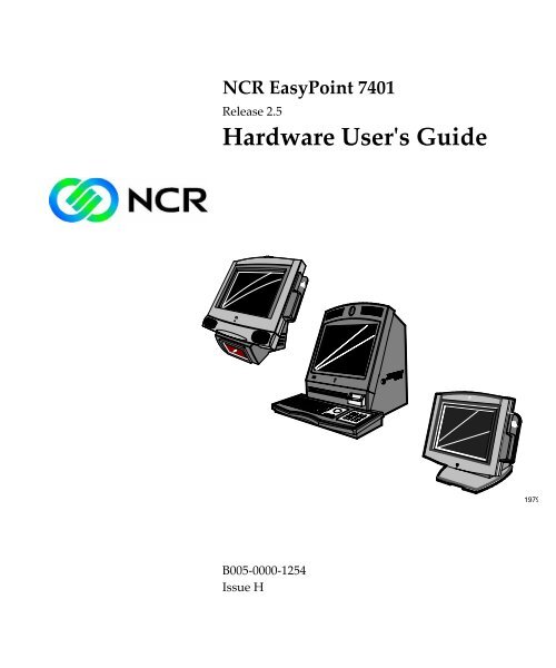
Chapter 1: <strong>7401</strong>-2xxx/3xxx Product Overview<br />
NCR<br />
Introduction<br />
Tilt Mount<br />
Fixed-Angle Mount<br />
18289<br />
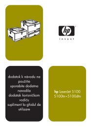
The NCR EasyPoint <strong>7401</strong> is an interactive touch screen terminal with<br />
retail functionality that supports a variety of kiosk and self‐service<br />
applications. The <strong>7401</strong> is housed in an integrated, compact cabinet and<br />
can be tilt mounted, fixed‐angle mounted or flush mounted.<br />
The major hardware features of the <strong>7401</strong> are a 12.1‐inch or 15‐inch flat<br />
panel display with touch screen input and LAN connectivity, plus<br />
optional magnetic stripe reader, infrared reader, scanner, stereo audio,<br />
self service printer and wireless LAN. It also supports custom kiosk<br />
environments.<br />
The <strong>7401</strong> is Internet/Intranet ready. System loading occurs from a<br />
network server, and software and data content are delivered from a<br />
server through standard Internet protocols.
1-2 Chapter 1: <strong>7401</strong>-2xxx/3xxx Product Overview<br />
Serial Number/Model Number Label<br />
Fixed-Angle Mount Label<br />
The unitʹs serial number, model number, tracer number, and date of<br />
manufacture are included on a label on the back of the Core Module.<br />
Refer to following sections for additional information.<br />
The serial number is repeated on the non‐MSR side of the Core<br />
Module.<br />
To view the label:<br />
• For non‐hinged mounts, remove the Core Module from the mount.<br />
• For hinged mounts, the Core Module does not have to be removed.<br />
NCR <strong>7401</strong>-3000-8000<br />
50-12345678<br />
Class/Model<br />
Serial Number<br />
Mfg<br />
Date: 11/15/01<br />
F000,F005,F024,F031,F050,F101,F200,F422,F503<br />
Date Manufactured<br />
Feature Number(s)<br />
19476
Chapter 1: <strong>7401</strong>-2xxx/3xxx Product Overview 1-3<br />
Tilt-Mount Label<br />
To view the label, tilt the Core Module and remove the cable cover.<br />
NCR <strong>7401</strong>-2000-8000<br />
50-12345678<br />
Class/Model<br />
Serial Number<br />
Mfg<br />
Date: 11/15/01<br />
F000,F005,F024,F031,F050,F101,F200,F422,F503<br />
Date Manufactured<br />
Feature Number(s)<br />
19477
1-4 Chapter 1: <strong>7401</strong>-2xxx/3xxx Product Overview<br />
Model Numbers<br />
The following table identifies <strong>7401</strong> terminal models.<br />
Model<br />
Description<br />
<strong>7401</strong>‐2212 Standard Model ‐ 12.1‐inch Capacitive Touch LCD,<br />
Ethernet Cable<br />
<strong>7401</strong>‐3212 Scanner Model ‐ 12.1‐inch Capacitive Touch LCD,<br />
Integrated Fixed Angle Mount, and Ethernet Cable (Uses 1<br />
RS‐232 Port for Scanner)<br />
<strong>7401</strong>‐2622 Bundled Model ‐ 12.1‐inch Capacitive Touch LCD,<br />
Celeron 700 MHz, 128 MB SDRAM, 10 GB <strong>Har</strong>d Drive,<br />
Adapter Board (F031), and Ethernet Cable<br />
<strong>7401</strong>‐2512 Standard Model ‐ 15‐inch Capacitive Touch LCD, Ethernet<br />
Cable<br />
<strong>7401</strong>‐2518 Standard Model ‐ 15‐inch Resistive Touch LCD, Ethernet<br />
Cable<br />
<strong>7401</strong>‐2625 Bundled Model ‐ 15‐inch Capacitive Touch LCD, Celeron<br />
700 MHz, 128 MB SDRAM, 10 GB <strong>Har</strong>d Drive, Adapter<br />
Board (F031), and Ethernet Cable<br />
<strong>7401</strong>‐2630 Bundled Model ‐ 15‐inch Capacitive Touch LCD, PIII 700<br />
MHz, 128 MB SDRAM, 20 GB <strong>Har</strong>d Drive, Adapter Board<br />
(F031), and Ethernet Cable<br />
<strong>7401</strong>‐2635 Bundled Model ‐ 15‐inch Capacitive Touch LCD, PIII 1<br />
GHz, 128 MB SDRAM, 20 GB <strong>Har</strong>d Drive, Adapter Board<br />
(F031), and Ethernet Cable<br />
<strong>7401</strong>‐2655 Bundled Model ‐ 15‐inch Capacitive Touch LCD, Celeron<br />
700 MHz, 128 MB SDRAM, 256 MB Flash Disk, Adapter<br />
Board (F031), and Ethernet Cable<br />
<strong>7401</strong>‐9512 No Bezel/Cabinet Model ‐ 15‐inch Capacitive LCD,<br />
Ethernet Cable
Chapter 1: <strong>7401</strong>-2xxx/3xxx Product Overview 1-5<br />
<strong>Har</strong>dware Modules<br />
Base Unit<br />
• Processor Board<br />
−<br />
−<br />
−<br />
−<br />
−<br />
−<br />
−<br />
−<br />
Pentium III/Celeron processor<br />
SVGA chipset (12‐inch monitor)<br />
XGA chipset (15‐inch monitor)<br />
MPEGII chipset<br />
1 MB Flash BIOS (not CMOS)<br />
Four RS‐232 ports (two optionally powered)<br />
10/100BaseT Ethernet LAN chipset, Wake‐on‐LAN support, and<br />
RJ‐45 port<br />
PC Audio with an internal mono speaker<br />
−<br />
−<br />
−<br />
−<br />
−<br />
−<br />
−<br />
−<br />
−<br />
−<br />
SoundBlaster ® 16 compatible audio chipset<br />
Two USB type A ports<br />
PS/2 keyboard port<br />
External VGA display port<br />
Dual display support<br />
External stereo speaker port<br />
Internal PS/2 mouse (dedicated to the touch screen)<br />
One SODIMM (Small Outline DIMM) RAM socket<br />
64 MB memory on board<br />
IDE support for a hard disk, a CD ROM, and an optional<br />
Compact Flash disk in place of the hard disk
1-6 Chapter 1: <strong>7401</strong>-2xxx/3xxx Product Overview<br />
<strong>Har</strong>dware Options<br />
• POS Connector Board<br />
− Cash drawer port (supports two drawers via a Y‐cable)<br />
− Internal parallel port (dedicated to the optional customer<br />
display)<br />
−<br />
Microphone<br />
• 12.1‐inch Operator Display – active capacitive touch LCD<br />
• 15‐inch Operator Display – active LCD with capacitive or resistive<br />
touch<br />
• 2.5‐inch low or high capacity hard disk<br />
• Integrated Motion Sensor, capable of waking up the terminal from<br />
a low power state<br />
• Integrated Power Supply<br />
• Reset switch which can be used to recover from a lock‐up condition<br />
• 3‐meter Ethernet cable<br />
• U.S. power cord<br />
• Intel Pentium III Processor<br />
• Integrated 3‐track ISO MSR<br />
• Integrated Scanner Module<br />
• Integrated Stereo Module<br />
• Integrated CD‐ROM<br />
• Integrated Infrared Sensor<br />
• PCMCIA (for wireless LAN)<br />
• Mounting options: Table‐top, Pedestal, Pole, Wall, Tilt/Swivel<br />
• 256 MB Compact Flash
Chapter 1: <strong>7401</strong>-2xxx/3xxx Product Overview 1-7<br />
• 64/128/256 MB memory<br />
• Cash drawers<br />
− 2113 Cash Drawer (modular)<br />
− 2189 Cash Drawer (modular)<br />
− 2260 Cash Drawer (modular)<br />
− Dual cash drawer cable<br />
• Printers:<br />
− 7158 Thermal Receipt/Impact Printer<br />
− 7167 Thermal Receipt/Impact Printer<br />
− 7194 Thermal Receipt Printer<br />
− 7197 Thermal Receipt Printer<br />
− Remote printer cables<br />
− Signal extenders for remote printers<br />
• <strong>7401</strong>‐K590 Self‐Service Printer<br />
• <strong>7401</strong>‐K580 Self‐Service Printer (Discontinued)<br />
• PC keyboard<br />
− Keyboard Shelf<br />
• USB RS‐232 Port Server<br />
− USB Serial Converter<br />
• 4055 Uninterruptible Power System (UPS)
1-8 Chapter 1: <strong>7401</strong>-2xxx/3xxx Product Overview<br />
Terminal Components not Supported<br />
It is important to note that the terminal does not support the following<br />
components.<br />
Not Supported<br />
CMOS for hard totals, logs, and<br />
tallies<br />
Removable media, e.g., a flex<br />
disk<br />
SLP terminal loading<br />
Keylock for security (X, L, R, S)<br />
ISA and PCI Expansion slots<br />
DVD ROM<br />
Internal UPS<br />
Manual Video and audio<br />
controls<br />
DOS, Windows 3.1, Windows<br />
NT 3.51, Windows 9x, OS/2<br />
133 MHz/266 MHz Pentium<br />
Processor<br />
Alternative Implementation<br />
<strong>Har</strong>d disk, flash disk, or server<br />
storage<br />
LAN communication to an NT server<br />
via standard protocols<br />
Local storage, TCP/IP networking and<br />
PXE loading<br />
Reset switch based security<br />
USB and LAN based devices (future)<br />
External UPS<br />
Software controlled<br />
Windows NT 4.0, Windows 2000,<br />
Windows XPe<br />
Intel Pentium III 500/700 MHz and 1<br />
GHz , and Celeron 450/550/600/700<br />
MHz processors
Chapter 1: <strong>7401</strong>-2xxx/3xxx Product Overview 1-9<br />
System Configuration Diagram<br />
7892<br />
7837<br />
2010 Coin<br />
Dispenser<br />
<strong>7401</strong><br />
Keyboard<br />
2336-K008<br />
7194<br />
7158<br />
RS232 (4)<br />
2 Optionally<br />
Powered<br />
PS/2 KBD<br />
VGA<br />
Note: 7194 and 7158 are<br />
available in both RS-232<br />
and USB.<br />
USB<br />
POS Connector Bd.<br />
Processor Board<br />
Ethernet<br />
<strong>7401</strong>-K580/K590<br />
Parallel<br />
Cash Dwr<br />
Audio<br />
SVideo<br />
2336-K007<br />
2260/2189<br />
2nd Cash Drawer<br />
(Y-Cable)<br />
2113<br />
18319b
1-10 Chapter 1: <strong>7401</strong>-2xxx/3xxx Product Overview<br />
Kit Configuration Diagram<br />
2336-K037<br />
<strong>7401</strong> w/K590<br />
<strong>7401</strong>-3xxx<br />
<strong>7401</strong>-2xxx<br />
2336-K052<br />
F501<br />
K542<br />
F502<br />
K533<br />
F/K059<br />
F511<br />
F512<br />
F521<br />
F101<br />
F504<br />
F505<br />
F201<br />
F200<br />
K540<br />
K536<br />
K543<br />
K530<br />
K535<br />
K523<br />
F/K590<br />
K525<br />
K534<br />
18318d-P
Chapter 1: <strong>7401</strong>-2xxx/3xxx Product Overview 1-11<br />
<strong>Har</strong>dware Module Descriptions<br />
Processor Board<br />
Processor/Chip Set<br />
The terminal uses an Intel architecture processor, which permits it to<br />
leverage existing software drivers and applications, as well as provide<br />
the greatest flexibility in choosing an operating system. This provides<br />
several other advantages:<br />
• Capable of SW MPEG‐1 or MPEG‐2 playback at 30 frames per<br />
second with 22 kHz stereo audio (may be limited by OS<br />
constraints).<br />
• SoundBlaster ® ‐compatible audio<br />
• Expansion capabilities for optional features and future<br />
requirements (ISA/PCI bus and USB)<br />
The following sections identify processors, system bus speed, and onboard<br />
memory available on <strong>7401</strong> processor boards:<br />
Release 1.0<br />
• Intel Mobile Pentium 166 MHz or 266 MHz Processor (PGA<br />
package) used with the Intel 430TX PC chipset. The 430TX chipset<br />
consists of the 82439TX System Controller (North Bridge chip), also<br />
called the MTXC, and the 82371AB (South Bridge chip), also called<br />
the PIIX4.<br />
• A 66 MHz system bus<br />
These Intel Mobile Pentium Processors have been discontinued.
1-12 Chapter 1: <strong>7401</strong>-2xxx/3xxx Product Overview<br />
Release 2.0 – 2.4<br />
• Intel Pentium III 500 MHz or 700 MHz Processor, or Intel Celeron<br />
450 MHz, 550 MHz, or 600 MHz Processor (µPGA package) used<br />
with the Intel 440BX PC chipset. The 440BX chipset consists of the<br />
82440BX System Controller (North Bridge chip), also called the<br />
MTXC, and the 82371AB (South Bridge chip), also called the PIIX4.<br />
• A 100 MHz system bus<br />
• 64 MB memory with ability to add SODIMMS to i<strong>ncr</strong>ease the<br />
memory capacity of the terminal<br />
Release 2.5<br />
• Intel 700 MHz Celeron Processor or Intel 1 GHz Pentium III<br />
Processor (BGA package) on board, removing the µPGA processor<br />
socket. Intel 440BX chipset same as in Release 2.0 – 2.5.<br />
• 100 MHz system bus and memory support, 64‐bit bus width, and<br />
AGP video interface.<br />
• 128 MB memory with ability to add SODIMMS to i<strong>ncr</strong>ease the<br />
memory capacity of the terminal<br />
Video Subsystem<br />
The video subsystem supports the following LCD types:<br />
• 12.1‐inch active matrix (TFT [thin film transistor]) 800x600 with 64<br />
k colors<br />
• 15‐inch active matrix (TFT) 1024x760 with 64 k colors<br />
Support for the LCD integrated display is provided internally. External<br />
support for SVGA monitors (800x600 [or better] resolution and 64 k [or<br />
better] colors) is provided by a CRT 15‐Pin D‐shell connector.
Chapter 1: <strong>7401</strong>-2xxx/3xxx Product Overview 1-13<br />
The LCD back lighting is also software controlled. In addition to OFF<br />
and ON modes, a dimmed mode is supported in the hardware to allow<br />
i<strong>ncr</strong>eased tube life. If appropriate software drivers are loaded, full<br />
brightness is restored when touched, motion detection (Motion Sensor<br />
section), or an application request (i.e., to play promotional material on<br />
a preset schedule).<br />
Ethernet 10/100Base-T LAN Communications<br />
The <strong>7401</strong> terminal has an Intel 82559 LAN Controller that supports<br />
10/100Base‐T Ethernet. Ethernet 100Base‐T is also known as ʺFast<br />
Ethernet.ʺ The Boot ROM for diskless boot functionality is included in<br />
the 1 MB system ROM. The hardware is compatible with the TCP/IP,<br />
DHCP, and TFTP protocols required for remote boot of the platform.<br />
Appropriate software must be used to enable each protocol used over<br />
the Ethernet link.<br />
The terminal may be connected to either a 10 MB/s or 100 MB/s<br />
Ethernet connection. The hardware automatically selects the correct<br />
speed (if enabled by software to do so).<br />
The LAN hardware supports wakeup packet capability as defined in<br />
the Device Class Power Management Specification, Network Device<br />
Class (available from Microsoftʹs web site).<br />
When the platform is in the Soft OFF state (refer to the Advanced Power<br />
Management section that follows), receipt of a Wakeup Packet on the<br />
LAN can return the system to the ON state, if this feature is enabled by<br />
software.<br />
Due to limitations of the LAN controller and the OS, all features<br />
described in the Network Device Class specification may not be<br />
available.
1-14 Chapter 1: <strong>7401</strong>-2xxx/3xxx Product Overview<br />
100Base‐T is wired identically to 10Base‐T, except that the twisted pair<br />
cable must be Category 5 and the hubs must permit 100 or 10/100 MB/s<br />
operation. Although 10Base‐T will operate on Category 3 twisted pair,<br />
or NCR ʺ747ʺ cable, an upgrade to Category 5 is required for<br />
100Base‐T.<br />
A customer desiring to use the terminal in an existing 10Base‐T<br />
environment can do so and simply run at 10 MB. In order to upgrade to<br />
100MB/s, Category 5 cable and 100 or 10/100 hubs must be installed.<br />
NCR strongly recommends the use of Category 5 for all new cabling,<br />
even if the customer initially intends to run only 10Base‐T.<br />
LED Indicators for Link Integrity (verifies cable and hub connection are<br />
good) and LAN speed is provided on the Processor Board near the row<br />
of connectors at the bottom of the e‐box. The LED is ON (yellow) when<br />
the speed is running at 100 MB/s.<br />
Link Integrity is provided to the PC chipset to permit boot‐up software<br />
to verify the presence of the LAN connection. Software must allow 2<br />
seconds after power‐up in order for the Link Integrity signal to become<br />
valid.
Chapter 1: <strong>7401</strong>-2xxx/3xxx Product Overview 1-15<br />
Wireless LAN Communications<br />
When a wired Ethernet connection is not desired, a wireless LAN<br />
adapter may be installed in the PCMCIA socket. This requires that the<br />
PCMCIA daughter‐card feature be installed. A wireless LAN used in<br />
the terminal must meet the following requirements:<br />
• Integrated antenna that meets the requirements of PCMCIA (PC<br />
Card) Extended Type 2 card definition (a maximum of 5‐cm<br />
additional length).<br />
• Power consumption within the capabilities of the PCMCIA<br />
daughter‐card.<br />
• Signaling requirements within the capabilities of the terminal<br />
PCMCIA interface. The main restriction is that DMA transactions<br />
are not supported over the PCMCIA interface.<br />
• Device drivers for the targeted operating system must exist.<br />
• Appropriate infrastructure (server support, Base Stations, Ceiling<br />
Antennas, etc) must be present in the installation site, and the<br />
maximum RF range of the wireless system must not be exceeded.<br />
Interoperability ‐ While the 802.11 standard provides an interoperable<br />
protocol definition, there are vendor‐specific extensions to the protocol<br />
that encourage users to stay with one supplierʹs equipment. This also<br />
applies to wireless infrastructure and access points, 802.11 does not<br />
govern this operation. Mixing of RF suppliers on a site is not<br />
recommended until the RF suppliers have demonstrated<br />
interoperability.<br />
The wireless networks operate at speeds of 1‐2 MB/s with 2 percent<br />
packet loss typical. The application developer must be aware of the<br />
performance limitations and design applications that are acceptable to<br />
the customer when run over the slower network.<br />
Remote Wakeup over the wireless network is not possible because the<br />
cards do not support it. An alternative is to use the system real‐time<br />
clock wake up at a scheduled time.
1-16 Chapter 1: <strong>7401</strong>-2xxx/3xxx Product Overview<br />
The wired Ethernet connection is not certified for use in configurations<br />
where a wireless adapter is installed.<br />
Universal Serial Bus<br />
Two USB Type‐A ports are provided on the terminal. USB Host<br />
Controller support is provided in hardware on the Processor Board.<br />
Note: Third party USB peripherals require support from the operating<br />
system, which is currently limited to Windows 2000 and Windows<br />
Xpe. The terminal must use the I/O Networks drivers to support the<br />
NCR USB printer and scanner products. These drives are available<br />
under Windows NT, Windows 2000, and Windows XPe.<br />
Serial Ports<br />
The <strong>7401</strong> Release 2.x processor boards provide two RS‐232 ports (9‐pin<br />
D‐shell connectors, Ports 1 and 2) directly on the board and support<br />
two additional RS‐232 ports. Ports 3 and 4 require an optional harness<br />
connection to the processor board. Ports 1 and 3 can be supplied with<br />
+12 V DC on Pin 9 when properly set up in the BIOS. The total power<br />
drawn by Ports 1 and/or 3 must be no greater than 1 amp at 12 V+ DC.<br />
Refer to the following table for RS‐232 pin‐out information.<br />
The BIOS permits flexibility in mapping resources. However, a fullyloaded<br />
system (2 PCMCIA cards that require IRQs, four serial ports in<br />
use, USB in use, parallel port in use, and MSR) may not have enough<br />
available IRQs to support all serial ports. Use a USB serial port<br />
expander to overcome this PC architecture limitation.
Chapter 1: <strong>7401</strong>-2xxx/3xxx Product Overview 1-17<br />
Port 2 shares hardware resources with the IRDA connection; if IRDA is<br />
in use, Port 3 is not available.<br />
RS-232 DB-9 Male Connector Pinout<br />
Pin Port A Port B<br />
1 DCD DCD<br />
2 RXD RXD<br />
3 TXD TXD<br />
4 DTR DTR<br />
5 GND GND<br />
6 DSR DSR<br />
7 RTS RTS<br />
8 CTS CTS<br />
9 RI or +12* RI<br />
* If Port 1 or 3 are powered, pin 9 will be +12 V.<br />
<strong>Har</strong>dware Monitor<br />
The hardware monitor generates an interrupt to the system whenever<br />
any of the internal voltages used by the system processor goes above or<br />
below the acceptable operating range. An interrupt is also generated<br />
when the temperature of the Processor exceeds safe levels. Software<br />
can use this indication to slow or stop the system and/or force a reset.<br />
PCI Expansion Header<br />
A single expansion header is provided to support optional features,<br />
such as the PCMCIA for Wireless LAN Board. This board supports two<br />
Type 2 or one Type 3 PCMCIA type cards.<br />
IDE Header<br />
A standard IDE header is provided to support the 2.5‐inch hard disk<br />
drive and integrated CD‐ROM. This header al supports the optional<br />
256 MB IDE compact flash available in place of the hard disk.
1-18 Chapter 1: <strong>7401</strong>-2xxx/3xxx Product Overview<br />
Audio<br />
The base unit has SoundBlaster‐compatible audio. Wave table<br />
synthesis is not supported. FM synthesis and MIDI are supported in<br />
the hardware, but requires software driver support to function.<br />
Higher quality integrated stereo speakers may be added as an option to<br />
the terminal. The amplifier is located on the Processor Board; the<br />
speaker output is provided on a header that receives the harness from<br />
the speaker module. In addition, a Line Out is provided on a 3.5 mm<br />
stereo jack that permits connection of external amplified speakers.<br />
The integrated stereo speakers, or an amplifier connected to Line Out,<br />
must be used in order to play SoundBlaster (audio subsystem) audio.<br />
However, an internal EUI speaker provides PC speaker functionality<br />
(beeps and tones) for all configurations.<br />
The volume control can be set during system configuration.<br />
The PC speaker sounds (such as beeps and touch clicks) are directed<br />
into the audio subsystem and are audible if speakers are connected.<br />
• Release 2.0 – 2.4 processor boards use a Cirrus/Crystal CS4614 (PCIbased)<br />
sound controller that supports DirectX 6 sound.<br />
• Release 2.5 processor boards use an ESS Allegro ES1989 sound<br />
controller that supports DirectX 8 sound.<br />
Magnetic Stripe Reader<br />
A 3‐track MSR head is available as an option. The ISO card format is<br />
supported.<br />
When card data is read, an interrupt is generated. A software device<br />
driver for the MSR must be loaded to enable the application to process<br />
the data.<br />
Touch Screen Controller<br />
The MicroTouch ʺExcaliburʺ chip is used to interface the touch panel.<br />
This controller supports MicroTouch capacitive panels.
Chapter 1: <strong>7401</strong>-2xxx/3xxx Product Overview 1-19<br />
In order to save an RS‐232 port, the touch data is delivered to the<br />
system through the mouse interface. This requires a mouse‐aware<br />
touch device driver for the appropriate OS.<br />
When the system is operating in the dimmed display mode, touch<br />
activity can restore full brightness if instructed by software to do so.<br />
When system is in low power mode, touch activity can generate the<br />
mouse port interrupt (IRQ12).<br />
Processor Board Connectors<br />
All connectors are either keyed or impossible to plug incorrectly due to<br />
mechanical design of the product.<br />
External Connectors<br />
VGA CRT RGB 15 pin D Shell<br />
Ethernet RJ45<br />
Dual USB Type A<br />
External Stereo speaker (3.5mm<br />
jack)<br />
Power supply<br />
RS‐232 9 pin D shell (two, one<br />
with +12 V power option)<br />
PS/2 Keyboard<br />
Customer Display<br />
Cash Drawer<br />
IRDA<br />
20‐pin high density RS‐232<br />
Conversion connector<br />
Microphone<br />
S‐Video<br />
Internal Connectors<br />
LCD<br />
Back light Inverter<br />
Integrated Speaker Module<br />
MSR<br />
Touch screen (PS/2)<br />
Integrated Scanner (<strong>7401</strong>)<br />
Motion Sensor / Power Indicator<br />
PCI Expansion header<br />
IDE<br />
Parallel port (POS Board header)<br />
Cash Drawer port (POS Board<br />
header)
1-20 Chapter 1: <strong>7401</strong>-2xxx/3xxx Product Overview<br />
Flash Disk Interface (Discontinued)<br />
The Release 2.0 – 2.5 processor boards provide support for a flash disk<br />
array in the form of an M‐Systems DiskOnChip. A 32‐pin socket is<br />
provided for this feature. The flash disk must be installed and enabled<br />
in BIOS Setup. This feature is not available on Release 2.5 processor<br />
boards.<br />
NCR Retail Specific <strong>Har</strong>dware<br />
The Processor Board contains logic that provides support for the<br />
custom retail interface. The logic controls the following features:<br />
• Dual Cash Drawer Support<br />
• Cash Drawer Diagnostic Support<br />
• Magnetic Stripe Reader Interface<br />
• Motion Detector<br />
• Touch Screen Interface<br />
Cash Drawer Support<br />
An integrated retail specific feature of the processor is the cash drawer<br />
circuitry. The onboard circuitry internal to the board provides the<br />
control for two external cash drawers. A portion of the POS Board<br />
header (J6) is provided on the board to interface to the dual cash<br />
drawer connector. Header J6 only contains the control signals; it does<br />
not provide power. Software controls the cash drawer(s) through I/O<br />
port 00Exh. This means it can be I/O ports E0/E1h, E2/E3h, E4/E5h, or<br />
EA/EBh depending on the configuration of the SMC I/O controllerʹs<br />
GPIO port(s). Default setting is E0/E1h.
Chapter 1: <strong>7401</strong>-2xxx/3xxx Product Overview 1-21<br />
Cash Drawer I/O Port Bit Definition:<br />
Bit # Description Bit = 1 Bit = 0<br />
7 Solenoid B Control Turns off solenoid<br />
output<br />
6 Solenoid A Control Turns off solenoid<br />
output<br />
Activates solenoid<br />
output<br />
Activates solenoid<br />
output<br />
5 Reserved Reserved Reserved<br />
4 Reserved Reserved Reserved<br />
3 Solenoid B Status Solenoid B output<br />
active<br />
2 Solenoid A Status Solenoid A output<br />
active<br />
Solenoid B output<br />
inactive<br />
Solenoid A output<br />
inactive<br />
1 Reserved Reserved Reserved<br />
0 Cash Drawer(s) Status Drawer(s) open Drawer(s) closed<br />
Note: Bits 2 and 3 are set to ʹ1ʹ by each device reset.<br />
The cash drawer interface can be diagnosed remotely. For security<br />
reasons, the cash drawer diagnostics mode must first be activated by<br />
pressing an external momentary switch (SW2). The intention is for<br />
authorized personnel to be present when the cash drawer diagnostic<br />
tests take place.<br />
There is only one cash drawer status signal; therefore, bit 0 is the status<br />
of either cash drawer or both cash drawers.
1-22 Chapter 1: <strong>7401</strong>-2xxx/3xxx Product Overview<br />
Power LED<br />
The Processor Board provides support for an external power LED<br />
through the onboard Motion/Power LED connector. This LED is<br />
controlled through the SMC 37C935 GPIO pins. Once the SMC chip is<br />
programmed to support the Power LED function on GPIO pin 13, the<br />
LED will be turned ʺonʺ anytime all power to the Processor Board is<br />
good. The systemʹs power management software has the option to turn<br />
the LED off indicating the system is in a power‐managed mode.<br />
MSR<br />
The MSR interface supports a maximum of 3 tracks of magnetic stripe<br />
information for support of ISO format cards. Activate the MSR<br />
interface by enabling it in BIOS Setup under IO Configuration. The<br />
MSR interface controller is a memory‐mapped device, which can reside<br />
at system memory addresses CA000, CC000, or D0000. If MSR<br />
capability is not desired, it may be disabled through BIOS Setup.<br />
Graphics Subsystem<br />
The Release 2.0 – 2.4 processor boards are equipped with an SMI Lynx<br />
SVGA LCD/CRT 3DM graphics controller with 8 MB of integrated<br />
synchronous graphics DRAM.<br />
The Release 2.5 processor board has an SMI Lynx 3DM/3DM+ graphics<br />
controller.<br />
The Processor Boards support linear addressing by creating a ʺholeʺ in<br />
the memory address space at the 63 MB boundary. When the system is<br />
configured for 64 MB and linear addressing is enabled, the last 1 MB of<br />
system memory is unusable; therefore, the board will report that total<br />
available system memory is 63 MB.<br />
Because a hole in memory creates a non‐contiguous address space,<br />
enabling linear addressing when total system DRAM is greater than 64<br />
MB is not recommended. Video linear addressing is enabled through<br />
PC Setup under the Integrated Peripherals menu.
Chapter 1: <strong>7401</strong>-2xxx/3xxx Product Overview 1-23<br />
The processor also supports VESA standards such as the VESA DPMS<br />
protocol to place a DPMS compliant monitor into power savings<br />
modes.<br />
Release 2.5 processor boards with the Lynx 3DM/3DM+ chip support<br />
the following DirectX 6 Direct Draw and Direct 3D graphics functions.<br />
• Rasterization acceleration<br />
• Z buffer<br />
• Alpha comparison<br />
• Texture filtering<br />
• Texture blending<br />
• Mimap support<br />
• Vertex and Global fogs<br />
• Diffuse and specular color<br />
• Alpha blending<br />
• Triangle and line drawing<br />
The following DirectX 8 functions are not supported:<br />
• TnL<br />
• Vertex shader<br />
• Pixel shader<br />
• Bump mapping<br />
• Box mapping<br />
The Release 1.0 Pentium processor board was equipped with a C&T<br />
69000/65555 SVGA LCD/CRT graphics controller with 2 MB of<br />
integrated synchronous graphics DRAM. The 69000/65555 is a 32‐bit<br />
graphics controller that combines a VGA controller, 32‐bit graphics<br />
engine, dual‐frequency clock synthesizer, and true‐color DAC in a<br />
single package. This processor board has been discontinued.
1-24 Chapter 1: <strong>7401</strong>-2xxx/3xxx Product Overview<br />
Resolutions Supported<br />
Resolution Colors Max Vfreq<br />
800x600x8bpp 256 85 Hz<br />
800x600x16bpp 64 k 85 Hz<br />
800x600x24bpp 16 M 85 Hz<br />
Colors Supported<br />
Resolution<br />
256 Colors<br />
(8-Bit)<br />
65,000 Colors<br />
(16-Bit)<br />
16.7 M Colors<br />
(24-Bit)<br />
800x600 512 k 1 MB 2 MB<br />
Dual Displays<br />
The Summa II Motherboard (Release 2.5) is dual display (LCD and<br />
CRT) capable. In a dual display environment the <strong>7401</strong> terminal<br />
supports 16‐bit color when both displays are connected to the<br />
motherboard. Both displays must have the same maximum resolution<br />
capability. Refer to the following information for details about the<br />
implementation of a dual display configuration.<br />
• Lynx Family Control Panel Specification 1.2 on the NCR 74xx Base<br />
System and Client Third party Drivers CD‐ROM (Product ID:<br />
D370‐0111‐0100) or in the video.exe self‐extracting Video Drivers<br />
file on the Retail Solutions Specific Third Party Products Drivers and<br />
Patches web site at:<br />
http://www.<strong>ncr</strong>..com/support/support_drivers_patches.asp?Class=retail_TPP.<br />
• Retail Customer Information Display User’s Guide (BD20‐1431‐B) on<br />
the NCR Information Products web site at:<br />
http://www.info.<strong>ncr</strong>.com/eHome.cfm
Chapter 1: <strong>7401</strong>-2xxx/3xxx Product Overview 1-25<br />
Board BIOS<br />
Processor boards use a Phoenix BIOS, which is stored in Flash ROM<br />
and easily upgraded through the network connection or serial port.<br />
The Flash EEPROM also contains the Setup utility, Power‐On Self Tests<br />
(POST), and APM 1.2 (Release 2.0‐2.4) or ACPI 2.0 (Release 2.5). The<br />
boards also supports system BIOS shadowing, permitting the BIOS to<br />
execute from onboard write‐protected DRAM.<br />
The BIOS displays a sign‐on message during POST identifying the type<br />
of BIOS and a four‐digit revision code.<br />
FLASH memory Implementation<br />
The Intel E28F800B5‐T70 Flash component is organized onboard as<br />
1024 k x 8 (1 MB). While a typical PC BIOS image including video and<br />
LAN boot ROM code normally fits in 256 kB on the Pentium board and<br />
512 kB on the Pentium III/Celeron board, the boards support a 1 MB<br />
flash ROM. The current Phoenix BIOS release only requires 256 kB of<br />
this 1 MB total. The Flash device contains the PC System BIOS along<br />
with the Video BIOS and LAN boot ROM which compresses the ROM<br />
images into a single binary image.<br />
The Flash device is divided into four areas, as described below.<br />
System Address FLASH Memory Area<br />
F0000H FFFFFH 64 kB Main BIOS<br />
EE000H EFFFFH 8 kB System BIOS Reserved during boot<br />
ED000H EDFFFH 4 kB Plug and Play ESCD Storage Area<br />
E0000H ECFFFH 52 kB System/VGA BIOS Reserved during boot
1-26 Chapter 1: <strong>7401</strong>-2xxx/3xxx Product Overview<br />
BIOS Upgrades<br />
Flash memory makes distributing BIOS upgrades easy. A new version<br />
of the BIOS can be installed from the hard disk, network or through a<br />
serial port.<br />
The disk‐based Flash upgrade utilities, Phlash.exe and WinPhlash,exe,<br />
ensure the upgrade BIOS extension matches the target system to<br />
prevent accidentally installing a BIOS for a different type of system.<br />
Setup Utility<br />
The ROM‐based Setup utility allows the system configuration to be<br />
modified without opening the system for most basic changes. The<br />
Setup utility is accessible only during the Power‐On Self Test (POST)<br />
by pressing the key after the POST memory test has begun and<br />
before boot begins. A prompt may be enabled that informs users to<br />
press the key to access Setup.<br />
An external alphanumeric keyboard is recommended for running the<br />
BIOS CMOS Setup Utility. Otherwise, a Touch Screen can be used.<br />
Plug and Play<br />
The Processor BIOS also has a setup option to support the Windows<br />
runtime plug and play utilities. When this option is selected, only<br />
devices critical to boot are assigned resources by the BIOS. Device<br />
Node information is available for all devices to ensure compatibility<br />
with Windows 95. System configuration information is stored in ESCD<br />
format. The ESCD data will be cleared upon loss of the CMOS voltage.<br />
Advanced Power Management<br />
The <strong>7401</strong> Release 2.0 – 2.4 Processor BIOS has support for both 1.1 and<br />
1.2 Advanced Power Management (APM). The version of APM drivers<br />
loaded in the operating system determines to which specification the<br />
BIOS adheres. In either case, the energy saving Standby mode can be<br />
initiated by a time‐out period set by the user.
Chapter 1: <strong>7401</strong>-2xxx/3xxx Product Overview 1-27<br />
When in Stand By mode, the Processor Board reduces power<br />
consumption by using the processor System Management Mode<br />
(SMM) capabilities and also spinning down hard drives and turning off<br />
VESA DPMS compliant monitors. During setup, the user may select<br />
which DPMS mode (Stand By, Suspend, Auto, or Off) is sent to the<br />
monitor. The ability to respond to external interrupts is fully<br />
maintained while in Stand By mode permitting the system to service<br />
requests such as in‐coming data or network messages while<br />
unattended. Keyboard or mouse activity may also be used to take the<br />
system out of the energy saving Stand By mode. When this occurs, the<br />
monitor and IDE drives are turned back on immediately.<br />
Advanced Power Management is achieved by the following:<br />
• DOS requires a driver (FS‐APM.dos)<br />
• NT requires a driver (NCRSYSM.SYS)<br />
• Windows 2000 must enable the operating system APM setting. The<br />
OS APM setting is disabled by default. NCR Gold Drivers are<br />
enabled in this setting by selecting:<br />
Start, Control Panel, Power Options, APM tab and check the box<br />
Enable Advance Power Management Support<br />
Click Ok to finish.<br />
ACPI<br />
The Release 2.5 terminal BIOS supports Advance Configuration Power<br />
Interface (ACPI) 2.0 power management. Primary differences between<br />
APM and ACPI are as follows:<br />
• On an APM‐ managed terminal, the BIOS determines when to<br />
switch between power states and also performs the switch. When<br />
using ACPI, the operating system determines when to switch and<br />
informs the BIOS to perform the switch.<br />
• APM must be enabled in the BIOS. ACPI is automatically active<br />
with the operating system.<br />
• ACPI Setup options are available in the OS Control Panel.
1-28 Chapter 1: <strong>7401</strong>-2xxx/3xxx Product Overview<br />
ACPI provides similar modes of operation as APM. The <strong>7401</strong> hardware<br />
supports four Power Management States.<br />
State<br />
OFF<br />
ON<br />
• APM Auto<br />
state<br />
• ACPI G0/S0<br />
Working state<br />
CONSERVE<br />
• APM Standby<br />
state<br />
• ACPI G1/S1<br />
Sleeping state<br />
SOFT OFF<br />
• APM Suspend<br />
State<br />
• ACPI G2/S5<br />
Soft Off state<br />
Characteristics<br />
AC power is not present. All RAM contents are lost.<br />
Power is on and fully supplied to all <strong>7401</strong> components. The display and<br />
touch panel are active. The CPU may be fully on or be in chip standby mode.<br />
This is transparent to the user and the application. Standby mode reduces<br />
power requirements and is controlled by the chip set and is entered/exited<br />
depending on the CPU’s utilization level. Transitioning between fully on<br />
and standby causes no delay.<br />
Power is on, but consumption is reduced by throttling back or completely<br />
stopping the system clock. Throttling is fully programmable. This is the<br />
primary means of reducing system power consumption and is used to help<br />
correct a high temperature warning level detected by the temperature<br />
monitor. Temperature may also be reduced by dimming the LCD. There is<br />
no user or application action required for this mode. When a Safe<br />
Temperature is detected, the system switches back to the ON state.<br />
Transitioning between ON and CONSERVE takes less than 10 milliseconds.<br />
Temperature has reached a critically high level, a LAN‐based Powerdown was<br />
received, or a system Shutdown occurred. Power consumption is reduced<br />
to its lowest level. All voltages are still present, but BIOS places each<br />
peripheral and chip into its lowest available power state. The chip set enters<br />
the Suspend‐to‐RAM mode. The LCD back light is turned off, blanking the<br />
display. RAM contents are preserved upon return to ON state unless<br />
software issues a reset. If this state was entered because of a LAN‐based<br />
Powerdown or system Shutdown, transitioning to the ON state can occur via<br />
LAN‐based reset or wakeup, Timer wake‐up, Touch activity, Motion<br />
Sensor, or keyboard. If SOFT OFF was entered because of a Critical<br />
Temperature, the ON state can be automatically transitioned to when a Safe<br />
Temperature is reached.
Chapter 1: <strong>7401</strong>-2xxx/3xxx Product Overview 1-29<br />
Operator Display<br />
NCR<br />
Tilt Mount<br />
Fixed-Angle Mount<br />
18289<br />
The <strong>7401</strong>‐2xxx and 3xxx have either a 12.1‐inch TFT (active matrix) or a<br />
15‐inch TFT.<br />
LCD Adapter Board<br />
The signals from the LCD header on the Processor Board are brought<br />
to the LCD on a harness. Since there are multiple pin configurations<br />
and connector types being used on the LCD, a small adapter board is<br />
used to receive the LCD harness and map the signals into the correct<br />
pin‐out for the LCD panel. This board has a connector that plugs<br />
directly into the LCD panel.<br />
LCD Backlight Inverter Module<br />
An Inverter Board supplies power for the LCD Backlight, which is a<br />
separate module in the terminal. The inverter has a connector that<br />
receives power, ground, and a Backlight dimming signal from the<br />
Processor Board. The inverter generates the high voltage necessary to<br />
start and run dual CCFL (cold‐cathode fluorescent lamps) Backlights.
1-30 Chapter 1: <strong>7401</strong>-2xxx/3xxx Product Overview<br />
A fuse located on the Inverter Board protects power to the inverter.<br />
This fuse protects the system from damage in the event of a Backlight<br />
or Inverter Board fault. The fuse is not field replaceable; if it blows, the<br />
safety characteristics of one or more components on the Inverter Board<br />
may have been compromised and the Inverter Board should be<br />
replaced.<br />
If one or both Backlight tubes become disconnected or otherwise opencircuited,<br />
protection circuitry shuts down the inverter. This avoids<br />
over‐powering a single tube and also protects against high voltage<br />
shorting.<br />
The Backlight tubes for the Active displays (TFT) can be replaced.<br />
Touch Screen<br />
The Touch Screen completely covers the LCD and is mounted directly<br />
in front of the LCD, behind the front plastic bezel of the terminal. The<br />
touch controller on the Processor Board supports capacitive and<br />
resistive touch glass.<br />
The touch glass has an integrated harness that is routed into the<br />
Processor Board enclosure and is connected to a header on the<br />
Processor Board.<br />
The touch glass has a glare‐reducing texture that also helps hide<br />
fingerprints.
Chapter 1: <strong>7401</strong>-2xxx/3xxx Product Overview 1-31<br />
Features<br />
Magnetic Stripe Reader<br />
A single 3‐track analog MSR is available as a feature, supporting ISO<br />
format cards. When the MSR is not desired, a filler piece for the MSR<br />
section is included to make the unit appear uniform.<br />
NCR<br />
MSR<br />
MSR<br />
18291
1-32 Chapter 1: <strong>7401</strong>-2xxx/3xxx Product Overview<br />
Printer Options<br />
The sections that follow provide an illustration and brief description of<br />
the available printer options.<br />
<strong>7401</strong>-K590 Self-Service Printer<br />
The K590 Printer is a self‐service, fast, silent, thermal printer that<br />
provides ʺunattended printing.ʺ The printer is housed in a secure<br />
cabinet that does not allow customer access to the paper while it is<br />
printing. It can print text, graphics and bar codes. It prints on paper<br />
that is 80 mm, 82.5 mm, or 114 mm wide. When printing is complete, a<br />
receipt presenter provides the cut receipt. The printer receives its<br />
power from an external power supply and has a serial interface.<br />
19055
Chapter 1: <strong>7401</strong>-2xxx/3xxx Product Overview 1-33<br />
7158 Printer<br />
The 7158 Printer is extremely fast, quiet, and reliable point‐of‐sale<br />
device. It consists of two specialized printers in one compact package: a<br />
thermal printer on top that prints receipts, and an impact slip printer in<br />
front to print on forms and checks that you insert. It receives its power<br />
from an external power supply, can be connected through a USB or<br />
serial port, and has a connector for cash drawers.<br />
17304<br />
7167 Printer<br />
The NCR 7167 Printer is a fast, quiet, relatively small and very reliable<br />
multi‐function printer. It prints receipts, validates and prints checks,<br />
and prints on a variety of single or multiple part forms. There is no<br />
journal as it is kept electronically by the host terminal. The printer<br />
features a dual interface, so it can connect to the host terminal either<br />
through a USB interface or RS‐232. It receives its power from an<br />
external power supply, and has a connector for cash drawers.<br />
19711e
1-34 Chapter 1: <strong>7401</strong>-2xxx/3xxx Product Overview<br />
7194 Printer<br />
The 7194 Printer is a high speed, high‐resolution printer, capable of<br />
both text and graphics printing. It offers direct thermal printing in a<br />
receipt station. It receives its power from an external power supply,<br />
can be connected through a USB or serial port, and has a connector for<br />
cash drawers.<br />
16437<br />
7197 Printer<br />
The NCR 7197 Printer is a fast, quiet, relatively small and very reliable<br />
multi‐function printer. It prints receipts and two‐color printing. The<br />
printer features a dual interface, so it can connect to the host terminal<br />
either through a USB interface or RS‐232. It receives its power from an<br />
external power supply, and has a connector for cash drawers.<br />
19712e
Chapter 1: <strong>7401</strong>-2xxx/3xxx Product Overview 1-35<br />
Other Integrated Devices and Indicators<br />
<strong>Har</strong>d Disk Drive<br />
A 2.5‐inch IDE hard disk is available to support Windows NT. The<br />
drive is the standard type that is used by notebook PCs.<br />
Reset Switch<br />
As a last resort, the Reset Switch can be used to reboot the system if the<br />
software reset port mechanisms fail. The switch is on the connector<br />
row at the bottom of the enclosure. Intentionally, it is not easily<br />
accessible, but can be operated without removing covers or using<br />
special tools.<br />
Reset Switch<br />
16454<br />
Except when testing software in a lab environment, always disconnect<br />
the AC power cord.<br />
Reset Procedure<br />
1. Gently press the Reset Switch and hold it in for at least four<br />
seconds. The screen goes blank.<br />
2. Release the Reset Switch and then gently press it again. The system<br />
reboots.
1-36 Chapter 1: <strong>7401</strong>-2xxx/3xxx Product Overview<br />
Internal Speaker<br />
The Internal Speaker is connected to the PC speaker output of the<br />
system chipset, not to the audio subsystem. It is connected to the<br />
Processor Board via a harness and mounted inside the Processor Board<br />
enclosure.<br />
POS Connector Board<br />
The POS Connector Board is a small daughter board that mounts<br />
directly on the Cash Drawer and Parallel Port header. Connectors on<br />
the edge of this board form a second connector row above the<br />
Processor Board connectors. Connectors are available for two cash<br />
drawers, a customer display and a microphone.<br />
Power for the cash drawers (24 V) and VFD customer display (5 V and<br />
12 V) is supplied by the Enhanced Power Supply through the parallel<br />
connector.<br />
Motion Sensor<br />
The terminal hardware can detect movement near the terminal and<br />
enables software to prompt system operation from a low‐power state.<br />
Application software may also be able to make use of motion detection<br />
when in the ON state if it is enabled by lower‐level software.<br />
NCR<br />
Motion Sensor<br />
Power/Status LED<br />
18290
Chapter 1: <strong>7401</strong>-2xxx/3xxx Product Overview 1-37<br />
Motion is detected as a change in ambient light level that is greater<br />
than a software‐controlled threshold.<br />
A photodiode mounted behind the front bezel of the unit senses<br />
ambient light levels. The photodiode resides on a small circuit board<br />
(the Motion Sensor Board). A harness connects the Motion Sensor<br />
Board to the amplifier and motion sensing logic on the Processor<br />
Board. The user Power/Status LED indicator shares this board.<br />
Power/Status LED<br />
The LED power indicator indicates that power is present. The LED is<br />
green when the processor and BIOS are operating properly. The LED is<br />
mounted behind the front bezel on the same board as the motion<br />
sensor.<br />
Power OK LED<br />
The Power OK LED is located behind the Cable Cover, between the<br />
Customer Display and Cash Drawer connectors.<br />
Power OK LED<br />
(5V and 24V)<br />
16453
1-38 Chapter 1: <strong>7401</strong>-2xxx/3xxx Product Overview<br />
LAN Status LEDs<br />
LAN Integrity<br />
(Green)<br />
LAN Speed:<br />
Yellow = 100 MB<br />
OFF = 10 MB<br />
16455<br />
Power Supply<br />
The terminal uses an AC adapter for its power supply, concealed in the<br />
terminal mounting. The supply is inaccessible when the terminal is in<br />
the normal operation and mounting position to prevent tampering, and<br />
sealed to help protect against spills or other environmental hazards.<br />
Note: The power supply automatically senses the proper AC voltage;<br />
therefore only normal servicing access is required.<br />
All power required to operate the base unit, PCMCIA option and<br />
PCMCIA cards, speaker option, scanner option, and bus‐powered USB<br />
peripherals is provided by the power supply.<br />
The Processor Board serves as the hub to distribute power to all<br />
terminal functions. Cash drawers, VFD customer display, PS/2<br />
keyboard, PCMCIA daughter board and slots, scanner (through RS‐232<br />
port), USB, hard disk, and the LCD all receive power through their<br />
respective Processor Board connectors.
Chapter 1: <strong>7401</strong>-2xxx/3xxx Product Overview 1-39<br />
Uninterruptible Power System (Optional)<br />
The 4055 Uninterruptible Power System (UPS) protects your<br />
equipment from various power related problems, providing visual and<br />
audible indicators which alert you to utility‐line failures. The 4055 is<br />
installed inside the pedestal mount, and includes a data line/LAN<br />
connection which ensures both the AC and data paths are protected<br />
from surges and noise transmitted through the power lines.<br />
Integrated Scanner Module (Optional)<br />
The scanner, power supply, and Scanner Controller Board are located<br />
inside the Fixed‐Angle Mount. The scanner interface is serial, and is<br />
connected to RS‐232/1, which is a powered serial port.<br />
Note: The Integrated Scanner feature includes the Fixed‐Angle Mount<br />
and cannot be used with the Table Top Mount.<br />
The <strong>7401</strong> Scanner is a modified NCR 7890 or NCR 7892 Scanner,<br />
however, there are a few differences. Refer to the NCR <strong>7401</strong>/7890 or<br />
7892 Scanner Differences chapter for additional information.<br />
Integrated Speaker Module (Optional)<br />
The Integrated Speaker feature provides two stereo speakers that<br />
attach to the bottom of the Core Module. The maximum output of the<br />
speakers is approximately 6 watts per channel.<br />
Compact Flash (Optional)<br />
The 256MB compact flash can be used in a Windows XP embedded<br />
environment. When using the Windows XP embedded OS, an<br />
additional 128MB SDRAM SODIMM is required to support the<br />
necessary virtual memory requirements. The 256MB compact flash<br />
replaces the hard drive in the unit.
1-40 Chapter 1: <strong>7401</strong>-2xxx/3xxx Product Overview<br />
USB RS-232 Port Server<br />
The USB RS‐232 Port Server is an intelligent, stackable expansion<br />
module that connects to the terminal Universal Serial Bus (USB) port,<br />
providing high‐speed RS‐232 serial ports.<br />
7454/<strong>7401</strong><br />
USB Port<br />
RS-232 Ports<br />
16944
Chapter 1: <strong>7401</strong>-2xxx/3xxx Product Overview 1-41<br />
Integrated CD-ROM Drive (Tilt Mount Model)<br />
The Integrated CD‐ROM Drive is located behind a cover on the Back<br />
Panel. To access the drive, loosen the spring‐loaded CD Cover Screw<br />
and remove the CD Cover by sliding it up as shown.<br />
CD Cover Screw<br />
CD Cover<br />
19230
1-42 Chapter 1: <strong>7401</strong>-2xxx/3xxx Product Overview<br />
Additional Connectors (Pentium III Board)<br />
The Pentium III Boards have three connectors that are not on the other<br />
Pentium Boards. Also available is a fourth connector for a microphone<br />
when a POS Connector Board is mounted to the Processor Board. The<br />
following illustration identifies these connectors.<br />
S-Video<br />
RS-232 Connector<br />
(COM 3 and COM 4)<br />
Microphone<br />
(optional)<br />
IRDA<br />
17999<br />
The following is a brief description of each connector.<br />
S-Video<br />
This connector provides a video connection to an S‐video monitor.<br />
RS-232 Connector<br />
This connector provides two additional RS‐232 ports. To add the<br />
ports, install the Dual RS‐232 Port Kit (7454‐F072) as described in<br />
the Feature Kits appendix. The Dual RS‐232 Cable provides two<br />
additional serial ports.<br />
Microphone<br />
This connector provides for audio input.<br />
IRDA<br />
This connector permits infrared communication between devices.<br />
18002
Chapter 1: <strong>7401</strong>-2xxx/3xxx Product Overview 1-43<br />
Compatibility<br />
LAN Communications<br />
The software associated with the terminal systems conform to the<br />
following standards:<br />
• Network Driver Interface Specification (NDIS 4)<br />
• IEEE 802.3 & 802.3u CSMA/CD (10/100 MB/s Ethernet)<br />
• IEEE 802.2 Link Level Control (LLC)<br />
• TCP/IP<br />
Application Programmability<br />
The software associated with the terminal systems conform to the<br />
following standards:<br />
• OLE for Retail POS 1.4<br />
• JavaPOS for Retail 1.4<br />
• HTML 4.0<br />
• ECMA Script<br />
• Java Development Kit 1.1.3<br />
Operating System Information<br />
The software associated with the terminal systems conform to the<br />
following standards:<br />
• Microsoft Windows NT<br />
• Microsoft Windows 2000<br />
• Windows Xpe
1-44 Chapter 1: <strong>7401</strong>-2xxx/3xxx Product Overview<br />
Migration<br />
Retail Applications<br />
Retail Peripherals<br />
• Existing TAPS‐based applications are not supported. These<br />
applications must be migrated to Windows NT.<br />
• Existing Windows 3.11‐based NICE applications are not supported.<br />
These applications must be migrated to Windows NT.<br />
• Existing OPOS‐based applications can be supported on terminals<br />
running Windows NT.<br />
• Windows NT, Windows 2000, and Windows XPe are the only<br />
supported operating systems.<br />
Since the system is a dedicated platform with limited expansion<br />
capability, a limited subset of the retail peripherals is supported. No<br />
support is provided for the following peripheral types:<br />
• OCIA Peripherals<br />
• RS‐485 Peripherals<br />
• Wedge Keyboard<br />
• Operator Line Display
Chapter 1: <strong>7401</strong>-2xxx/3xxx Product Overview 1-45<br />
Retail Systems<br />
This release of software does not support the following features found<br />
in previous retail systems:<br />
Platform<br />
• ISA Cards<br />
• Standard PCI Cards<br />
• Multi‐port Serial<br />
• Memory Dump<br />
Networks<br />
• M‐11<br />
• StarLAN<br />
• 10base2 Ethernet<br />
• Token Ring<br />
• NetBEUI /Net BIOS<br />
• NetWare<br />
Platform Load<br />
• SLP, SLF, RPL<br />
• PCMCIA Disk, PCMCIA Flash Disk
Chapter 2: <strong>7401</strong>-4xxx Product Overview<br />
Introduction<br />
19889d<br />
The <strong>7401</strong>‐4xxx model is a ruggedized version ideal for unattended use<br />
in financial environments. The major hardware features of this model<br />
are a 15 inch flat panel display with touch screen input, LAN<br />
connectivity, stereo audio, an integrated secure cabinet, an 80‐column<br />
printer, a motorized MSR or card‐swipe MSR, an integrated Pin Pad,<br />
and the integrated rugged keyboard with trackball.
2-2 Chapter 2: <strong>7401</strong>-4xxx Product Overview<br />
Serial Number/Model Number Label<br />
The unitʹs serial number, model number, tracer number, and date of<br />
manufacture are included on a label located inside the cabinet on the<br />
left side above the printer module.<br />
NCR <strong>7401</strong>-4512-8001<br />
50-12345678<br />
Class/Model<br />
Serial Number<br />
Date: 03/15/02<br />
F015,F026,F105,F122,F202,F431,F595<br />
Mfg<br />
Date Manufactured<br />
Feature Number(s)<br />
19890<br />
<strong>7401</strong>-4xxx Model Numbers<br />
<strong>7401</strong>‐4512 15‐in. Capacitive LCD, CD‐ROM, 4 Serial Ports, Parallel<br />
Port, Ethernet Cable<br />
<strong>7401</strong>‐4665 15‐in. Capacitive LCD, CD‐ROM, 4 Serial Ports, Parallel<br />
Port, Ethernet Cable, Celeron 700 MHz, and 10 GB HDD<br />
<strong>7401</strong>‐4675 15‐in. Capacitive LCD, CD‐ROM, 4 Serial Ports, Parallel<br />
Port, Ethernet Cable, PIII 1 GHz, and 20 GB HDD
Chapter 2: <strong>7401</strong>-4xxx Product Overview 2-3<br />
<strong>Har</strong>dware Modules<br />
Base Unit<br />
• Processor Board<br />
− Pentium III/Celeron processor<br />
− XGA chipset (15‐inch monitor)<br />
− MPEGII chipset<br />
− 1 MB Flash BIOS (not CMOS)<br />
− Four RS‐232 ports (two optionally powered)<br />
− 10/100BaseT Ethernet LAN chipset, Wake‐on‐LAN support, and<br />
RJ‐45 port<br />
− PC Audio with an internal mono speaker<br />
−<br />
−<br />
−<br />
−<br />
−<br />
−<br />
−<br />
−<br />
−<br />
−<br />
SoundBlaster ® 16 compatible audio chipset<br />
Two USB type A ports<br />
PS/2 keyboard port<br />
External VGA display port<br />
Dual display support<br />
External stereo speaker port<br />
Internal PS/2 mouse (dedicated to the touch screen)<br />
One SODIMM (Small Outline DIMM) RAM socket<br />
64 MB memory on board<br />
IDE support for a hard disk, a CD ROM, and an optional flash<br />
disk<br />
• POS Connector Board<br />
− Internal parallel port (dedicated to the optional customer<br />
display)<br />
− Microphone<br />
• 15‐inch Operator Display – active LCD with capacitive or resistive<br />
touch
2-4 Chapter 2: <strong>7401</strong>-4xxx Product Overview<br />
<strong>Har</strong>dware Options<br />
• 2.5‐inch low or high capacity hard disk<br />
• Integrated Motion Sensor, capable of waking up the terminal from<br />
a low power state<br />
• Integrated CD‐ROM<br />
• Integrated Infrared Sensor<br />
• Integrated Power Supply<br />
• Full Page Printer<br />
• Reset switch which can be used to recover from a lock‐up condition<br />
• Table‐top mount<br />
• 3‐meter Ethernet cable<br />
• U.S. power cord<br />
• Integrated 3‐track ISO MSR<br />
• Motorized Card Reader<br />
• 64/128 MB or 256 MB memory<br />
• 256 MB Compact Flash<br />
• Ruggedized Keyboard<br />
• Pin Pad<br />
• Trackball
Chapter 2: <strong>7401</strong>-4xxx Product Overview 2-5<br />
Terminal Components not Supported<br />
It is important to note that the terminal does not support the following<br />
components.<br />
Not Supported<br />
CMOS for hard totals, logs,<br />
and tallies<br />
Removable media, e.g., a<br />
flex disk<br />
SLP terminal loading<br />
Keylock for security (X, L,<br />
R, S)<br />
ISA and PCI Expansion<br />
slots<br />
DVD ROM<br />
Internal UPS<br />
Manual Video and audio<br />
controls<br />
DOS, Windows 3.1,<br />
Windows NT 3.51,<br />
Windows 9x, OS/2<br />
133/266 MHz Pentium<br />
Processors<br />
Alternative Implementation<br />
<strong>Har</strong>d disk, compact flash, or server<br />
storage<br />
LAN communication to an NT server<br />
via standard protocols<br />
Local storage, TCP/IP networking and<br />
PXE loading<br />
Reset switch based security<br />
USB and LAN based devices (future)<br />
External UPS<br />
Software controlled<br />
Windows NT 4.0, Windows 2000,<br />
Windows XPe<br />
Intel Pentium III 500/700 MHz, 1 GHz,<br />
and Celeron 450/550/600/700 MHz<br />
processors
2-6 Chapter 2: <strong>7401</strong>-4xxx Product Overview<br />
System Configuration Diagram<br />
Full Page<br />
Printer<br />
Power<br />
Supply<br />
Power<br />
LAN<br />
Parallel<br />
Speaker<br />
Speakers<br />
IRDA<br />
IRDA<br />
Receiver<br />
Processor Board<br />
MSR<br />
Swipe<br />
MSR<br />
S-Video<br />
(Powered)<br />
COM1<br />
USB 1<br />
USB 2<br />
RS-232 Ports<br />
(Powered)<br />
COM2 COM3 COM4<br />
USB<br />
Camera<br />
(Kit)<br />
Trackball<br />
Pin Pad<br />
Motorized<br />
Card<br />
Reader<br />
Power<br />
Supply<br />
19794b
Chapter 2: <strong>7401</strong>-4xxx Product Overview 2-7<br />
<strong>Har</strong>dware Module Descriptions<br />
Processor Board<br />
Processor/Chip Set<br />
The terminal uses an Intel architecture processor, which permits it to<br />
leverage existing software drivers and applications, as well as provide<br />
the greatest flexibility in choosing an operating system. This provides<br />
several other advantages:<br />
• Capable of SW MPEG‐1 or MPEG‐2 playback at 30 frames per<br />
second with 22 kHz stereo audio (may be limited by OS<br />
constraints).<br />
• SoundBlaster ® ‐compatible audio<br />
• Expansion capabilities for optional features and future<br />
requirements (ISA/PCI bus and USB)<br />
Release 2.4<br />
• Intel Pentium III 500 MHz or 700 MHz Processor, or Intel Celeron<br />
550 MHz or 600 MHz Processor (µPGA package) used with the<br />
Intel 440BX PC chipset. The 440BX chipset consists of the 82440BX<br />
System Controller (North Bridge chip), also called the MTXC, and<br />
the 82371AB (South Bridge chip), also called the PIIX4.<br />
• A 100 MHz system bus<br />
• 64 MB memory with ability to add SODIMMS to i<strong>ncr</strong>ease the<br />
memory capacity of the terminal
2-8 Chapter 2: <strong>7401</strong>-4xxx Product Overview<br />
Release 2.5<br />
• Intel 700 MHz Celeron Processor or Intel 1 GHz Pentium III<br />
Processor (BGA package) on board, removing the µPGA processor<br />
socket. Intel 440BX chipset same as in Release 2.4<br />
• 100 MHz system bus and memory support, 64‐bit bus width, and<br />
AGP video interface.<br />
• 128 MB memory with ability to expand like Release 2.4.<br />
Video Subsystem<br />
The video subsystem supports the following LCD types:<br />
• 15‐inch active matrix (TFT) 768x1024 with 64 k colors<br />
Support for the LCD integrated display is provided internally. External<br />
support for SVGA monitors (800x600 [or better] resolution and 64 k [or<br />
better] colors) is provided by a CRT 15‐Pin D‐shell connector.<br />
The LCD back lighting is also software controlled. In addition to OFF<br />
and ON modes, a dimmed mode is supported in the hardware to allow<br />
i<strong>ncr</strong>eased tube life. If appropriate software drivers are loaded, full<br />
brightness is restored when touched, motion detection (Motion Sensor<br />
section), or an application request (i.e., to play promotional material on<br />
a preset schedule).<br />
Ethernet 10/100Base-T LAN Communications<br />
The <strong>7401</strong>‐4xxx terminal has an Intel 82559 LAN Controller that<br />
supports 10/100Base‐T Ethernet. Ethernet 100Base‐T is also known as<br />
ʺFast Ethernet.ʺ The Boot ROM for diskless boot functionality is<br />
included in the 1 MB system ROM. The hardware is compatible with<br />
the TCP/IP, DHCP, and TFTP protocols required for remote boot of the<br />
platform. Appropriate software must be used to enable each protocol<br />
used over the Ethernet link.<br />
The terminal may be connected to either a 10 MB/s or 100 MB/s<br />
Ethernet connection. The hardware automatically selects the correct<br />
speed (if enabled by software to do so).
Chapter 2: <strong>7401</strong>-4xxx Product Overview 2-9<br />
The LAN hardware supports wakeup packet capability as defined in<br />
the Device Class Power Management Specification, Network Device<br />
Class (available from Microsoftʹs web site).<br />
When the platform is in the Soft OFF state (refer to the Advanced Power<br />
Management section that follows), receipt of a Wakeup Packet on the<br />
LAN can return the system to the ON state, if this feature is enabled by<br />
software.<br />
Due to limitations of the LAN controller and the OS, all features<br />
described in the Network Device Class specification may not be<br />
available.<br />
100Base‐T is wired identically to 10Base‐T, except that the twisted pair<br />
cable must be Category 5 and the hubs must permit 100 or 10/100 MB/s<br />
operation. Although 10Base‐T will operate on Category 3 twisted pair,<br />
or NCR ʺ747ʺ cable, an upgrade to Category 5 is required for 100Base‐<br />
T.<br />
A customer desiring to use the terminal in an existing 10Base‐T<br />
environment can do so and simply run at 10 MB. In order to upgrade to<br />
100MB/s, Category 5 cable and 100 or 10/100 hubs must be installed.<br />
NCR strongly recommends the use of Category 5 for all new cabling,<br />
even if the customer initially intends to run only 10Base‐T.<br />
LED Indicators for Link Integrity (verifies cable and hub connection are<br />
good) and LAN speed is provided on the Processor Board near the row<br />
of connectors at the bottom of the e‐box. The LED is ON (yellow) when<br />
the speed is running at 100 MB/s.<br />
Link Integrity is provided to the PC chipset to permit boot‐up software<br />
to verify the presence of the LAN connection. Software must allow 2<br />
seconds after power‐up in order for the Link Integrity signal to become<br />
valid.
2-10 Chapter 2: <strong>7401</strong>-4xxx Product Overview<br />
Wireless LAN Communications<br />
When a wired Ethernet connection is not desired, a wireless LAN<br />
adapter may be installed in the PCMCIA socket. This requires that the<br />
PCMCIA daughter‐card feature be installed. A wireless LAN used in<br />
the terminal must meet the following requirements:<br />
• Integrated antenna that meets the requirements of PCMCIA (PC<br />
Card) Extended Type 2 card definition (a maximum of 5‐cm<br />
additional length).<br />
• Power consumption within the capabilities of the PCMCIA<br />
daughter‐card.<br />
• Signaling requirements within the capabilities of the terminal<br />
PCMCIA interface. The main restriction is that DMA transactions<br />
are not supported over the PCMCIA interface.<br />
• Device drivers for the targeted operating system must exist.<br />
• Appropriate infrastructure (server support, Base Stations, Ceiling<br />
Antennas, etc) must be present in the installation site, and the<br />
maximum RF range of the wireless system must not be exceeded.<br />
Interoperability ‐ While the 802.11 standard provides an interoperable<br />
protocol definition, there are vendor‐specific extensions to the protocol<br />
that encourage users to stay with one supplierʹs equipment. This also<br />
applies to wireless infrastructure and access points, 802.11 does not<br />
govern this operation. Mixing of RF suppliers on a site is not<br />
recommended until the RF suppliers have demonstrated<br />
interoperability.<br />
The wireless networks operate at speeds of 1‐2 MB/s with 2 percent<br />
packet loss typical. The application developer must be aware of the<br />
performance limitations and design applications that are acceptable to<br />
the customer when run over the slower network.<br />
Remote Wakeup over the wireless network is not possible because the<br />
cards do not support it. An alternative is to use the system real‐time<br />
clock wake up at a scheduled time.
Chapter 2: <strong>7401</strong>-4xxx Product Overview 2-11<br />
Depending on the OS environment, Remote Boot may be supported,<br />
but due to the slow network speed a large boot image may take an<br />
unacceptably long time to load. The application developer needs to<br />
ensure that the load is of reasonable size.<br />
The wired Ethernet connection is not certified for use in configurations<br />
where a wireless adapter is installed.<br />
Universal Serial Bus<br />
Two USB Type‐A ports are provided on the terminal. USB Host<br />
Controller support is provided in hardware on the Processor Board.<br />
Note: Third party USB peripherals require support from the operating<br />
system, which is currently limited to Windows 2000 and Windows<br />
Xpe. The terminal must use the I/O Networks drivers to support the<br />
NCR USB printer and scanner products. These drives are available<br />
under Windows NT, Windows 2000, and Windows XPe.<br />
Serial Ports<br />
The <strong>7401</strong>‐4xxx Celeron/Pentium III processor board provides two RS‐<br />
232 ports (9‐pin D‐shell connectors, Ports 1 and 2) directly on the board<br />
and supports two additional RS‐232 ports. Ports 3 and 4 require an<br />
optional harness connection to the board. Ports 1 and 3 can be supplied<br />
with +12 V DC on Pin 9 when properly set up in the BIOS. The total<br />
power drawn by Ports 1 and/or 3 must be within the limits of the<br />
capabilities of the power supply. Refer to the following table for RS‐232<br />
pin‐out information.<br />
The BIOS permits flexibility in mapping resources. However, a fullyloaded<br />
system (2 PCMCIA cards that require IRQs, four serial ports in<br />
use, USB in use, parallel port in use, and MSR) may not have enough<br />
available IRQs to support all serial ports. Use a USB serial port<br />
expander to overcome this PC architecture limitation.
2-12 Chapter 2: <strong>7401</strong>-4xxx Product Overview<br />
Port 2 shares hardware resources with the IRDA connection; if IRDA is<br />
in use, Port 3 is not available.<br />
RS-232 DB-9 Male Connector Pinout<br />
Pin Port A Port B<br />
1 DCD DCD<br />
2 RXD RXD<br />
3 TXD TXD<br />
4 DTR DTR<br />
5 GND GND<br />
6 DSR DSR<br />
7 RTS RTS<br />
8 CTS CTS<br />
9 RI or +12* RI<br />
* If Port 1 or 3 are powered, pin 9 will be +12 V.<br />
<strong>Har</strong>dware Monitor<br />
The hardware monitor generates an interrupt to the system whenever<br />
any of the internal voltages used by the system processor goes above or<br />
below the acceptable operating range. An interrupt is also generated<br />
when the temperature of the Processor exceeds safe levels. Software<br />
can use this indication to slow or stop the system and/or force a reset.<br />
PCI Expansion Header<br />
A single expansion header is provided to support optional features,<br />
such as the PCMCIA for Wireless LAN Board. This board supports two<br />
Type 2 or one Type 3 PCMCIA type cards.<br />
IDE Header<br />
A standard IDE header is provided to support a 2.5‐inch hard disk<br />
drive and an integrated CD‐ROM. This header al supports the optional<br />
256 MB IDE compact flash available in place of the hard disk.
Chapter 2: <strong>7401</strong>-4xxx Product Overview 2-13<br />
Audio<br />
The base unit has SoundBlaster‐compatible audio. Wave table<br />
synthesis is not supported. FM synthesis and MIDI are supported in<br />
the hardware, but requires software driver support to function.<br />
Higher quality integrated stereo speakers may be added as an option to<br />
the terminal. The amplifier is located on the Processor Board; the<br />
speaker output is provided on a header that receives the harness from<br />
the speaker module. In addition, a Line Out is provided on a 3.5 mm<br />
stereo jack that permits connection of external amplified speakers.<br />
The integrated stereo speakers, or an amplifier connected to Line Out,<br />
must be used in order to play SoundBlaster (audio subsystem) audio.<br />
However, an internal EUI speaker provides PC speaker functionality<br />
(beeps and tones) for all configurations.<br />
The volume control can be set during system configuration.<br />
The PC speaker sounds (such as beeps and touch clicks) are directed<br />
into the audio subsystem and are audible if speakers are connected.<br />
• Release 2.0 – 2.4 processor boards use a Cirrus/Crystal CS4614 (PCIbased)<br />
sound controller that supports DirectX 6 sound.<br />
• Release 2.5 processor boards use an ESS Allegro ES1989 sound<br />
controller that supports DirectX 8 sound.<br />
Magnetic Stripe Reader<br />
A 3‐track MSR head is available as an option. The ISO card format is<br />
supported.<br />
When card data is read, an interrupt is generated. A software device<br />
driver for the MSR must be loaded to enable the application to process<br />
the data.<br />
Touch Screen Controller<br />
The MicroTouch ʺExcaliburʺ chip is used to interface the touch panel.<br />
This controller supports MicroTouch capacitive panels.
2-14 Chapter 2: <strong>7401</strong>-4xxx Product Overview<br />
In order to save an RS‐232 port, the touch data is delivered to the<br />
system through the mouse interface. This requires a mouse‐aware<br />
touch device driver for the appropriate OS.<br />
When the system is operating in the dimmed display mode, touch<br />
activity can restore full brightness if instructed by software to do so.<br />
When system is in low power mode, touch activity can generate the<br />
mouse port interrupt (IRQ12).<br />
Processor Board Connectors<br />
All connectors are either keyed or impossible to plug incorrectly due to<br />
mechanical design of the product.<br />
External Connectors<br />
VGA CRT RGB 15 pin D Shell<br />
Ethernet RJ45<br />
Dual USB Type A<br />
External Stereo speaker<br />
(3.5mm jack)<br />
Power supply<br />
RS‐232 9 pin D shell (two, one<br />
with +12 V power option)<br />
PS/2 Keyboard<br />
Customer Display<br />
Cash Drawer<br />
IRDA<br />
20‐pin high density RS‐232<br />
Conversion connector<br />
Microphone<br />
S‐Video<br />
Internal Connectors<br />
LCD<br />
Back light Inverter<br />
Integrated Speaker Module<br />
MSR<br />
Touch screen (PS/2)<br />
Integrated Scanner (<strong>7401</strong>)<br />
Motion Sensor / Power Indicator<br />
PCI Expansion header<br />
IDE<br />
Parallel port (POS Board header)<br />
Cash Drawer port (POS Board<br />
header)
Chapter 2: <strong>7401</strong>-4xxx Product Overview 2-15<br />
Flash Disk Interface (Discontinued)<br />
The <strong>7401</strong>‐45xx processor board provides support for a flash disk array<br />
in the form of an M‐Systems DiskOnChip. A 32‐pin socket is provided<br />
for this feature. The flash disk must be installed and enabled in BIOS<br />
Setup. This feature is not available on the <strong>7401</strong>‐46xx processor boards.<br />
NCR Retail Specific <strong>Har</strong>dware<br />
The <strong>7401</strong>‐4xxx Processor Board contains logic that provides support for<br />
the custom retail interface. The logic controls the following features:<br />
• Magnetic Stripe Reader Interface<br />
• Motion Detector<br />
• Touch Screen Interface<br />
MSR<br />
The MSR interface supports a maximum of 3 tracks of magnetic stripe<br />
information for support of ISO format cards. Activate the MSR<br />
interface by enabling it in BIOS Setup under IO Configuration. The<br />
MSR interface controller is a memory‐mapped device, which can reside<br />
at system memory addresses CA000, CC000, or D0000. If MSR<br />
capability is not desired, it may be disabled through BIOS Setup.<br />
Power LED<br />
The Processor Board provides support for an external power LED<br />
through the onboard Motion/Power LED connector. This LED is<br />
controlled through the SMC 37C935 GPIO pins. Once the SMC chip is<br />
programmed to support the Power LED function on GPIO pin 13, the<br />
LED will be turned ʺonʺ anytime all power to the Processor Board is<br />
good. The systemʹs power management software has the option to turn<br />
the LED off indicating the system is in a power‐managed mode.
2-16 Chapter 2: <strong>7401</strong>-4xxx Product Overview<br />
Graphics Subsystem<br />
The <strong>7401</strong>‐45xx processor boards are equipped with a SMI Lynx SVGA<br />
LCD/CRT 3DM graphics controller with 8 MB of integrated<br />
synchronous graphics DRAM. The <strong>7401</strong>‐46xx processor boards have an<br />
SMI Lynx 3DM/3DM+ graphics controller.<br />
The processor boards support linear addressing by creating a ʺholeʺ in<br />
the memory address space at the 63 MB boundary. When the system is<br />
configured for 64 MB and linear addressing is enabled, the last 1 MB of<br />
system memory is unusable; therefore, the board will report that total<br />
available system memory is 63 MB.<br />
Because a hole in memory creates a non‐contiguous address space,<br />
enabling linear addressing when total system DRAM is greater than 64<br />
MB is not recommended. Video linear addressing is enabled through<br />
PC Setup under the Integrated Peripherals menu.<br />
The processor also supports VESA standards such as the VESA DPMS<br />
protocol to place a DPMS compliant monitor into power savings<br />
modes.<br />
Resolutions Supported<br />
Resolution Colors Max Vfreq<br />
800x600x8bpp 256 85 Hz<br />
800x600x16bpp 64 k 85 Hz<br />
800x600x24bpp 16 M 85 Hz<br />
Colors Supported<br />
Resolution<br />
256 Colors<br />
(8-Bit)<br />
65,000 Colors<br />
(16-Bit)<br />
16.7 M Colors<br />
(24-Bit)<br />
800x600 512 k 1 MB 2 MB
Chapter 2: <strong>7401</strong>-4xxx Product Overview 2-17<br />
DirectX Support<br />
<strong>7401</strong>‐46xx processor boards with the Lynx 3DM/3DM+ chip support<br />
the following DirectX 6 Direct Draw and Direct 3D graphics functions.<br />
• Rasterization acceleration<br />
• Z buffer<br />
• Alpha comparison<br />
• Texture filtering<br />
• Texture blending<br />
• Mimap support<br />
• Vertex and Global fogs<br />
• Diffuse and specular color<br />
• Alpha blending<br />
• Triangle and line drawing<br />
The following DirectX 8 functions are not supported:<br />
• TnL<br />
• Vertex shader<br />
• Pixel shader<br />
• Bump mapping<br />
• Box mapping
2-18 Chapter 2: <strong>7401</strong>-4xxx Product Overview<br />
Dual Displays<br />
The <strong>7401</strong>‐46xx processor boards are dual display (LCD and CRT)<br />
capable. In a dual display environment the <strong>7401</strong> terminal supports<br />
16‐bit color when both displays are connected to the motherboard.<br />
Both displays must have the same maximum resolution capability.<br />
Refer to the following information for details about the implementation<br />
of a dual display configuration.<br />
• Lynx Family Control Panel Specification 1.2 on the NCR 74xx Base<br />
System and Client Third party Drivers CD‐ROM (Product ID:<br />
D370‐0111‐0100) or in the video.exe self‐extracting Video Drivers<br />
file on the Retail Solutions Specific Third Party Products Drivers and<br />
Patches web site at:<br />
http://www.<strong>ncr</strong>..com/support/support_drivers_patches.asp?Class=retail_TPP.<br />
• Retail Customer Information Display User’s Guide (BD20‐1431‐B) on<br />
the NCR Information Products web site at:<br />
http://www.info.<strong>ncr</strong>.com/eHome.cfm<br />
Board BIOS<br />
Processor boards use a Phoenix BIOS, which is stored in Flash ROM<br />
and easily upgraded through the network connection or serial port.<br />
The Flash EEPROM also contains the Setup utility, Power‐On Self Tests<br />
(POST), and APM 1.2 (<strong>7401</strong>‐45xx) or ACPI 2.0 (<strong>7401</strong>‐46xx). The boards<br />
also supports system BIOS shadowing, permitting the BIOS to execute<br />
from onboard write‐protected DRAM.<br />
The BIOS displays a sign‐on message during POST identifying the type<br />
of BIOS and a four‐digit revision code.
Chapter 2: <strong>7401</strong>-4xxx Product Overview 2-19<br />
FLASH memory Implementation<br />
The Intel E28F800B5‐T70 Flash component is organized onboard as<br />
1024 k x 8 (1 MB). While a typical PC BIOS image including video and<br />
LAN boot ROM code normally fits in 256 kB on the Pentium board and<br />
512 kB on the Pentium III/Celeron board, the boards support a 1 MB<br />
flash ROM. The current Phoenix BIOS release only requires 256 kB of<br />
this 1 MB total. The Flash device contains the PC System BIOS along<br />
with the Video BIOS and LAN boot ROM which compresses the ROM<br />
images into a single binary image.<br />
The Flash device is divided into four areas, as described below.<br />
System Address<br />
FLASH Memory Area<br />
F0000H FFFFFH 64 kB Main BIOS<br />
EE000H EFFFFH 8 kB System BIOS Reserved during boot<br />
ED000H EDFFFH 4 kB Plug and Play ESCD Storage Area<br />
E0000H ECFFFH 52 kB System/VGA BIOS Reserved during boot<br />
BIOS Upgrades<br />
Flash memory makes distributing BIOS upgrades easy. A new version<br />
of the BIOS can be installed from the hard disk, network or through a<br />
serial port.<br />
The disk‐based Flash upgrade utilities, Phlash.exe and WinPhlash.exe,<br />
ensure the upgrade BIOS extension matches the target system to<br />
prevent accidentally installing a BIOS for a different type of system.
2-20 Chapter 2: <strong>7401</strong>-4xxx Product Overview<br />
Setup Utility<br />
The ROM‐based Setup utility allows the system configuration to be<br />
modified without opening the system for most basic changes. The<br />
Setup utility is accessible only during the Power‐On Self Test (POST)<br />
by pressing the key after the POST memory test has begun and<br />
before boot begins. A prompt may be enabled that informs users to<br />
press the key to access Setup.<br />
An external alphanumeric keyboard is recommended for running the<br />
BIOS CMOS Setup Utility. Otherwise, a Touch Screen can be used.<br />
Plug and Play<br />
The Processor BIOS also has a setup option to support the Windows<br />
runtime plug and play utilities. When this option is selected, only<br />
devices critical to boot are assigned resources by the BIOS. Device<br />
Node information is available for all devices to ensure compatibility<br />
with Windows 95. System configuration information is stored in ESCD<br />
format. The ESCD data will be cleared upon loss of the CMOS voltage.<br />
Advanced Power Management<br />
The <strong>7401</strong>‐45xx processor BIOS has support for 1.2 Advanced Power<br />
Management (APM). The version of APM drivers loaded in the<br />
operating system by the user will determine to which specification the<br />
BIOS will adhere. In either case, the energy saving Standby mode can<br />
be initiated by a time‐out period set by the user.<br />
When in Stand By mode, the Processor Board reduces power<br />
consumption by utilizing the processor System Management Mode<br />
(SMM) capabilities and also spinning down hard drives and turning off<br />
VESA DPMS compliant monitors. During setup, the user may select<br />
which DPMS mode (Stand By, Suspend, Auto, or Off) is sent to the<br />
monitor.
Chapter 2: <strong>7401</strong>-4xxx Product Overview 2-21<br />
The ability to respond to external interrupts is fully maintained while<br />
in Stand By mode allowing the system to service requests such as incoming<br />
data or network messages while unattended. The user may<br />
also make any keyboard or mouse activity to take the system out of the<br />
energy saving Stand By mode. When this occurs, the monitor and IDE<br />
drives are turned back on immediately.<br />
Advanced Power Management (APM) is achieved by the following:<br />
• DOS requires a driver (FS‐APM.dos)<br />
• NT requires a driver (NCRSYSM.SYS)<br />
• Windows 2000 must enable the operating system APM setting. The<br />
OS APM setting is disabled by default. NCR Gold Drivers are<br />
enabled in this setting by selecting:<br />
Start, Control Panel, Power Options, APM tab and check the box<br />
Enable Advance Power Management Support<br />
Click Ok to finish.<br />
ACPI<br />
The <strong>7401</strong>‐46xx terminal BIOS supports Advance Configuration Power<br />
Interface (ACPI) 2.0 power management. Primary differences between<br />
APM and ACPI are as follows:<br />
• On an APM‐ managed terminal, the BIOS determines when to<br />
switch between power states and also performs the switch. When<br />
using ACPI, the operating system determines when to switch and<br />
informs the BIOS to perform the switch.<br />
• APM must be enabled in the BIOS. ACPI is automatically active<br />
with the operating system.<br />
• ACPI Setup options are available in the OS Control Panel.<br />
Refer to the table in the ACPI section of “Chapter 2: <strong>7401</strong>‐2xxx and 3xxx<br />
Product Overview” for a comparison of the operation modes (states)<br />
supported by APM and ACPI power management.
2-22 Chapter 2: <strong>7401</strong>-4xxx Product Overview<br />
Operator Display<br />
19889d<br />
The <strong>7401</strong>‐4xxx has a 15‐inch TFT (thin film transistor) 1024x760 with 65<br />
K colors display.<br />
LCD Adapter Board<br />
The signals from the LCD header on the Processor Board are brought<br />
to the LCD on a harness. Since there are multiple pin configurations<br />
and connector types being used on the LCD, a small adapter board is<br />
used to receive the LCD harness and map the signals into the correct<br />
pin‐out for the LCD panel. This board has a connector that plugs<br />
directly into the LCD panel.
Chapter 2: <strong>7401</strong>-4xxx Product Overview 2-23<br />
LCD Backlight Inverter Module<br />
An Inverter Board supplies power for the LCD Backlight, which is a<br />
separate module in the terminal. The inverter has a connector that<br />
receives power, ground, and a Backlight dimming signal from the<br />
Processor Board. The inverter generates the high voltage necessary to<br />
start and run dual CCFL (cold‐cathode fluorescent lamps) Backlights.<br />
A fuse located on the Inverter Board protects power to the inverter.<br />
This fuse protects the system from damage in the event of a Backlight<br />
or Inverter Board fault. The fuse is not field replaceable; if it blows, the<br />
safety characteristics of one or more components on the Inverter Board<br />
may have been compromised and the Inverter Board should be<br />
replaced.<br />
If one or both Backlight tubes become disconnected or otherwise opencircuited,<br />
protection circuitry shuts down the inverter. This avoids<br />
over‐powering a single tube and also protects against high voltage<br />
shorting.<br />
The Backlight tubes for the Active displays (TFT) can be replaced.<br />
Touch Screen<br />
The Touch Screen completely covers the LCD and is mounted directly<br />
in front of the LCD, behind the front plastic bezel of the terminal. The<br />
touch controller on the Processor Board supports capacitive and<br />
resistive touch glass.<br />
The touch glass has an integrated harness that is routed into the<br />
Processor Board enclosure and is connected to a header on the<br />
Processor Board.<br />
The touch glass has a glare‐reducing texture that also helps hide<br />
fingerprints.
2-24 Chapter 2: <strong>7401</strong>-4xxx Product Overview<br />
Features<br />
Integrated Speakers<br />
LCD<br />
Touchscreen<br />
MSR<br />
Keylock<br />
Keyboard<br />
Motorized<br />
Card Reader<br />
Trackball<br />
Secure Cabinet with Integrated Speakers<br />
Pin Pad<br />
19889a<br />
The <strong>7401</strong>‐4xxx cabinet has an anti‐vandal keylock that secures the<br />
cabinet in a closed position. The cabinet has no exposed screws,<br />
however, the rear of the cabinet is designed to accept brackets for<br />
signage and branding. Supervisory and service personnel can unlock<br />
the cabinet to replace the paper roll or perform maintenance on the<br />
terminal. Integrated stereo speakers are included in the top of the <strong>7401</strong>‐<br />
4xxx Bezel that surrounds the LCD Touch Screen module.
Chapter 2: <strong>7401</strong>-4xxx Product Overview 2-25<br />
Ruggedized Keyboard with Trackball<br />
The <strong>7401</strong>‐4xxx terminal has an anti‐vandal, spill resistant keyboard<br />
with trackball. The keyboard cover and keys, and the trackball are<br />
constructed of heavy duty, non‐destructive metal to withstand the<br />
extra use that occurs in unattended environments. U.S. and U.K.<br />
keyboard layouts are available as features. Other country‐specific<br />
keyboard layouts are available as kits. The Keyboard and Trackball are<br />
mounted in a keyboard tray that slides forward when the cabinet is<br />
open to permit easier access to the inside of the terminal for service<br />
personnel.<br />
For <strong>7401</strong>‐4xxx terminals with a U.K. keyboard (F130, F131, or F132),<br />
changes are required to the Regional Settings in the Control Panel.<br />
Refer to Chapter 4 for details.<br />
Pin Pad<br />
A secure anti‐vandal pin pad, constructed of non‐destructive metal is<br />
available as a feature. The Pin Pad with 10 numeric and 6 function keys<br />
is integrated into the keyboard tray next to the keyboard and trackball.<br />
The Pin Pad has a 64 KB memory for application use and 64 KB for<br />
data storage. It has programmable protocols and speeds (1200‐19200<br />
bps). When the personal identification number (PIN) is entered, the Pin<br />
Pad combines the PIN with the card data, e<strong>ncr</strong>ypts this information,<br />
and sends it to the host for verification. This device has a serial<br />
interface and is powered by a COM Port C. The Port C Powered Port<br />
option must be set in the BIOS. The Pin Pad is pre‐configured for<br />
e<strong>ncr</strong>yption by an authorized e<strong>ncr</strong>yption facility before it is integrated<br />
into the keyboard. OPOS support is not available with the Pin Pad
2-26 Chapter 2: <strong>7401</strong>-4xxx Product Overview<br />
Motorized Card Reader<br />
Magnetic Stripe Reader<br />
An optional Motorized Card Reader is available to provide MSR cardreading<br />
functionality similar to an ATM. When inserted, the card is fed<br />
into the reader and is retained there until the transaction is complete.<br />
The Motorized Card Reader has on‐board intelligence to process<br />
Magstripe Cards, Smart Cards, and Memory Cards:<br />
• Supports bi‐directional read of magnetic stripe data (3‐track)<br />
• Reads and writes all ISO 7816 T=0, T=1 micro‐processor Smart<br />
Cards<br />
• Accepts cards with CP8 and ISO positions<br />
• The card reader uses a vendor‐provided Windows Driver. OPOS<br />
support is not available with the motorized card reader.<br />
• This device is powered by a 12 VDC power supply.<br />
A single 3‐track analog MSR is available as a feature, supporting ISO<br />
format cards. When the MSR is not desired, a filler piece for the MSR<br />
section is included to make the unit appears uniform.
Chapter 2: <strong>7401</strong>-4xxx Product Overview 2-27<br />
Full Page Printer<br />
The <strong>7401</strong>‐4xxx has a full page thermal sheet printer that provides high<br />
resolution 300 dpi (11.81 dots per mm) printing with a loop presenter<br />
and cutter.<br />
Paper Roll<br />
Printhead<br />
Lever<br />
Paper<br />
Presenter<br />
19798e<br />
• The printer uses a large 6 in. diameter paper roll (650 ft. at 3.2 Mil<br />
thickness) with selectable paper widths from 165 mm to 216 mm<br />
(6.5 in. to 8.5 in.).<br />
• A Registration Mark sensor is supported for setting paper lengths.<br />
• Printer sensors provide alerts for paper out, paper low, paper in<br />
presenter, Printhead temperature, Printhead level position, and<br />
paper jam.<br />
• The Printer uses a vendor‐provided Windows Driver. OPOS<br />
support is not available with the full page printer.<br />
• This device is powered by a 24 VDC power supply.
2-28 Chapter 2: <strong>7401</strong>-4xxx Product Overview<br />
Other Integrated Devices and Indicators<br />
<strong>Har</strong>d Disk Drive<br />
A 2.5‐inch IDE hard disk is available to support Windows NT. The<br />
drive is the standard type that is used by notebook PCs.<br />
Integrated CD-ROM<br />
An integrated CD‐ROM is mounted to the back of the core module<br />
behind the LCD Touch Screen inside the cabinet. The CD‐ROM is used<br />
to install terminal software and can be used for other functions<br />
requiring a CD‐ROM.<br />
Reset Switch<br />
As a last resort, the Reset Switch can be used to reboot the system if the<br />
software reset port mechanisms fail. The switch is on the connector<br />
row at the bottom of the enclosure. Intentionally, it is not easily<br />
accessible, but can be operated without removing covers or using<br />
special tools.<br />
Reset Switch<br />
19901a<br />
Except when testing software in a lab environment, always disconnect<br />
the AC power cord.<br />
Reset Procedure<br />
1. Gently press the Reset Switch and hold it in for at least four<br />
seconds. The screen goes blank.<br />
2. Release the Reset Switch and then gently press it again. The system<br />
reboots.
Chapter 2: <strong>7401</strong>-4xxx Product Overview 2-29<br />
Compact Flash<br />
The 256MB compact flash can be used in a Windows XP embedded<br />
environment. When using the Windows XP embedded OS, an<br />
additional 128MB SDRAM SODIMM is required to support the<br />
necessary virtual memory requirements. The 256MB compact flash<br />
replaces the hard drive in the unit.<br />
Internal Speaker<br />
The Internal Speaker is connected to the PC speaker output of the<br />
system chipset, not to the audio subsystem. It is connected to the<br />
Processor Board via a harness and mounted inside the Processor Board<br />
enclosure.<br />
POS Connector Board<br />
The POS Connector Board is a small daughter board that mounts<br />
directly on the Cash Drawer and Parallel Port header. Connectors on<br />
the edge of this board form a second connector row above the<br />
Processor Board connectors. Connectors are available for two cash<br />
drawers, a customer display and a microphone.<br />
Power for the cash drawers (24 V) and VFD customer display (5 V and<br />
12 V) is supplied by the Enhanced Power Supply through the parallel<br />
connector.<br />
USB Camera<br />
The integrated USB Camera (available as a kit) supports the capture of<br />
a video image of individuals operating the EasyPoint <strong>7401</strong>‐46xx<br />
terminal.
2-30 Chapter 2: <strong>7401</strong>-4xxx Product Overview<br />
Motion Sensor<br />
The terminal hardware can detect movement near the terminal and<br />
enables software to prompt system operation from a low‐power state.<br />
Application software may also be able to make use of motion detection<br />
when in the ON state if it is enabled by lower‐level software.<br />
USB<br />
Camera<br />
IRDA<br />
Motion Sensor<br />
Power/Status LED<br />
Motion is detected as a change in ambient light level that is greater<br />
than a software‐controlled threshold.<br />
A photodiode mounted behind the front bezel of the unit senses<br />
ambient light levels. The photodiode resides on a small circuit board<br />
(the Motion Sensor Board). A harness connects the Motion Sensor<br />
Board to the amplifier and motion sensing logic on the Processor<br />
Board. The user Power/Status LED indicator shares this board.<br />
19889f<br />
Power/Status LED<br />
The LED power indicator indicates that power is present. The LED is<br />
green when the processor and BIOS are operating properly. The LED is<br />
mounted behind the front bezel on the same board as the motion<br />
sensor.
Chapter 2: <strong>7401</strong>-4xxx Product Overview 2-31<br />
Power OK LED<br />
The Power OK LED is located behind the Cable Cover, between the<br />
Customer Display and Cash Drawer connectors.<br />
Power OK<br />
(5V and 24 V)<br />
19901d<br />
LAN Status LEDs<br />
LAN Integrity<br />
(Green)<br />
LAN Speed<br />
Yellow = 100 MB<br />
OFF = 10 MB<br />
19901c<br />
Power Supply<br />
The terminal uses an AC adapter for its power supply, mounted inside<br />
the cabinet. The supply is inaccessible when the terminal is in the<br />
normal operation with the cabinet closed. The mounting position to<br />
prevent tampering, and sealed to help protect against spills or other<br />
environmental hazards.<br />
Note: The power supply automatically senses the proper AC voltage;<br />
therefore only normal servicing access is required.
2-32 Chapter 2: <strong>7401</strong>-4xxx Product Overview<br />
All power required to operate the base unit, PCMCIA option and<br />
PCMCIA cards, speaker option, scanner option, and bus‐powered USB<br />
peripherals is provided by the power supply.<br />
The Processor Board serves as the hub to distribute power to all<br />
terminal functions. Cash drawers, VFD customer display, PS/2<br />
keyboard, PCMCIA daughter board and slots, scanner (through RS‐232<br />
port), USB, hard disk, and the LCD all receive power through their<br />
respective Processor Board connectors.<br />
Motorized Card Reader Power Supply<br />
The Motorized Card Reader uses an AC adapter for its power supply,<br />
mounted on the inside of the cabinet.<br />
Full Page Printer Power Supply<br />
The Full Page Printer uses an AC adapter for its power supply,<br />
mounted inside the cabinet under the printer.<br />
Integrated Speakers<br />
The <strong>7401</strong>‐4xxx includes two stereo speakers in the top of the Bezel<br />
above the LCD Touch Screen. The maximum output of the speakers is<br />
approximately 6 watts per channel.
Chapter 2: <strong>7401</strong>-4xxx Product Overview 2-33<br />
EasyPoint 45 Pedestal<br />
A cone‐shaped, basic pedestal for the <strong>7401</strong>‐4xxx terminal. The pedestal<br />
is black and is metal and wood construction. The base of the pedestal<br />
has the following features:<br />
• Mounting holes to secure the unit to the floor<br />
• Adjustable feet<br />
• Cable access door<br />
• Space for an NCR 4055 UPS<br />
• Cable routing hole and channel<br />
20047a
Chapter 3: <strong>7401</strong>-2xxx/3xxx <strong>Har</strong>dware Installation<br />
Introduction<br />
Installation Summary<br />
The <strong>7401</strong>‐2xxx and 3xxx terminals are fully assembled at the factory.<br />
This chapter explains the mounting options and how to connect<br />
optional hardware components to these terminals.<br />
The terminal should be removed from the shipping packaging and<br />
visual checks made to verify the correct hardware configuration. The<br />
system is then configured and any communication cables are<br />
connected.<br />
Only after inspection should the power cord be attached to the system<br />
and then connected to the AC power source. Power‐up self‐tests will<br />
run to verify basic functionality.<br />
ROM‐based setup should be used to configure network options. Full<br />
configuration depends upon the system server and the management<br />
web site.
3-2 Chapter 3: <strong>7401</strong>-2xxx/3xxx <strong>Har</strong>dware Installation<br />
Installation Restrictions<br />
• Before installing the terminal, read and follow the guidelines in the<br />
NCR EasyPoint <strong>7401</strong> Site Preparation Guide and the NCR<br />
Workstation and Peripheral AC Wiring Guide.<br />
• Install the terminal near an electrical outlet that is easily accessible.<br />
Use the power cord as a power‐disconnect device.<br />
• Do not permit any object to rest on the power cord. Do not locate<br />
the terminal where the power cord can be walked on.<br />
• Use a grounding strap or touch a grounded metal object to<br />
discharge any static electricity from your body before servicing the<br />
terminal.<br />
• If the power cord is replaced, it must be replaced with the same<br />
type of cord with the protective shroud.<br />
• Do not route the power cord through openings with sharp edges.<br />
Caution: This unit contains hazardous voltages and should only be<br />
serviced by qualified service personnel.<br />
Caution: DO NOT connect or disconnect the transaction printer while<br />
the terminal is connected to AC power. This can result in system or<br />
printer damage.<br />
Warning: The <strong>7401</strong> must be mounted securely to prevent a hazard. It<br />
must be installed in accordance with local building codes. The post<br />
or wall on which the unit is mounted should be able to withstand<br />
four times the weight of the unit, which is approximately 20 lbs.<br />
(9 kg).
Chapter 3: <strong>7401</strong>-2xxx/3xxx <strong>Har</strong>dware Installation 3-3<br />
Connecting the Cables<br />
Fixed-Angle Mount (F504)<br />
The cable connectors are located behind the Core Module. The<br />
procedure for accessing the connectors is different for Fixed‐Angle<br />
Mounts and Tilt Mounts.<br />
1. Remove the screws that secure the Core Module to the Fixed‐Angle<br />
Mount.<br />
Core Module<br />
Fixed Angle Mount<br />
Remove Screws<br />
(One on each side)<br />
17339
3-4 Chapter 3: <strong>7401</strong>-2xxx/3xxx <strong>Har</strong>dware Installation<br />
2. Raise the bottom of the Core Module, pull out the Core Module<br />
Support and rest the Core Module on the Core Module Support.<br />
Core Module<br />
Metal Locking<br />
Tabs<br />
Keyboard Port<br />
Core Module<br />
Support<br />
3. Route the cables as described in the following section, Cable<br />
Routing.<br />
17340
Chapter 3: <strong>7401</strong>-2xxx/3xxx <strong>Har</strong>dware Installation 3-5<br />
Fixed-Angle Mount (F503)<br />
1. Remove the screw that secures the Core Module to the Fixed‐Angle<br />
Mount.<br />
Core Module<br />
Remove Screws<br />
(one on each side)<br />
Pedestal Mount<br />
16396
3-6 Chapter 3: <strong>7401</strong>-2xxx/3xxx <strong>Har</strong>dware Installation<br />
2. Remove the Core Module from the Fixed‐Angle Mount.<br />
16397<br />
3. Route the cables as described in the following section, Cable<br />
Routing.
Chapter 3: <strong>7401</strong>-2xxx/3xxx <strong>Har</strong>dware Installation 3-7<br />
Cable Routing<br />
The cables can be routed either out the bottom or rear of the Fixed‐<br />
Angle Mount. The Power Cord is shipped from the factory routed<br />
through the bottom exit hole in the Fixed‐Angle Mount. To route the<br />
cables out the rear exit, you must move the grommet from the bottom<br />
exit to the rear exit hole.<br />
Since these openings have different shapes, you must trim the<br />
grommet to length.<br />
1. Remove the grommet from the bottom exit hole.<br />
Grommet<br />
Rear Exit<br />
Bottom Exit<br />
16481
3-8 Chapter 3: <strong>7401</strong>-2xxx/3xxx <strong>Har</strong>dware Installation<br />
2. Press the grommet along the bottom edge of the rear exit and cut it<br />
to length.<br />
Measure<br />
and Cut<br />
16482<br />
3. Install the remainder of the grommet to the other three sides of the<br />
opening.<br />
Trim the<br />
Excess<br />
16483<br />
4. Trim the excess length.
Chapter 3: <strong>7401</strong>-2xxx/3xxx <strong>Har</strong>dware Installation 3-9<br />
Cable Connector Identification<br />
The cable connectors are located on the back of the Core Module.<br />
CRT<br />
LAN<br />
S-Video<br />
USB 1<br />
USB 2<br />
COM 1<br />
Keyboard<br />
PS/2<br />
COM 2<br />
Power<br />
Microphone<br />
(optional)<br />
RS-232<br />
(COM 3 & 4)<br />
Parallel<br />
Speaker<br />
Audio Out<br />
Cash Drawer<br />
IRDA<br />
18011<br />
Note: COM1 and COM3 can be powered ports. They are enabled in<br />
the BIOS.<br />
Note: The COM3 & COM4 RS‐232 ports require the Dual RS‐232 Port<br />
Kit (7454‐F072) feature<br />
After connecting the cables, reassemble the terminal.
3-10 Chapter 3: <strong>7401</strong>-2xxx/3xxx <strong>Har</strong>dware Installation<br />
Tilt Mount<br />
Tilt Mount cable connectors are located on the underside of the Core<br />
Module, under a cable cover.<br />
1. Tilt the display to access the cable connectors.<br />
Cable Cover<br />
Thumb Screw<br />
15968<br />
2. Loosen the thumbscrew that secures the Cable Cover and remove<br />
the cover.
Chapter 3: <strong>7401</strong>-2xxx/3xxx <strong>Har</strong>dware Installation 3-11<br />
Cable Routing<br />
The Tilt Mount has three places to secure cables to the base of the unit<br />
by using a cable tie wrap. Remove the power supply cover or customer<br />
display from the base of the unit, two thumb screws on bottom rear,<br />
and use a tie wrap to secure the Ethernet cable to one of the provided<br />
molded cable tie holders on the base. This should provide sufficient<br />
strain relief to prevent the cable from becoming tight and damaging the<br />
connector on the Processor Board.<br />
The peripheral cables are routed down through the Mount Assembly<br />
and out the rear of the unit.<br />
Bottom View<br />
16413a
3-12 Chapter 3: <strong>7401</strong>-2xxx/3xxx <strong>Har</strong>dware Installation<br />
Cable Connector Identification<br />
1. Connect the peripheral and LAN cables. The illustration below can<br />
be used to identify the connectors on the terminal. See the sections<br />
that follow for specific installation instructions for each of the<br />
peripherals.<br />
Audio Out<br />
Speaker<br />
CRT<br />
LAN<br />
S-Video<br />
USB 1<br />
USB 2<br />
COM 1<br />
RS-232<br />
(COM 3 & 4)<br />
Keyboard<br />
PS/2<br />
COM 2<br />
Parallel<br />
Power<br />
IRDA<br />
Microphone<br />
(optional)<br />
Cash Drawer<br />
Note: COM1 and COM3 can be powered ports. They are enabled in<br />
the BIOS.<br />
18010<br />
Note: The COM3 & COM4 RS‐232 ports require the Dual RS‐232 Port<br />
Kit (7454‐F072) feature<br />
2. After installing the peripheral and LAN cables replace the cable<br />
cover and re‐tighten the thumbscrew.
Chapter 3: <strong>7401</strong>-2xxx/3xxx <strong>Har</strong>dware Installation 3-13<br />
Installing Peripherals<br />
This section describes how to install transaction printers and other<br />
peripherals on the <strong>7401</strong>‐2xxx and 3xxx terminals.<br />
Installing a Transaction Printer<br />
The following printers can connect through a non‐powered RS‐232 or<br />
USB connector. They all require an external power supply. The<br />
illustrations show how to connect to the 7194 printer. Connecting to the<br />
other three printers is done in the same manner. Refer to the<br />
corresponding printer owner’s guide for illustrations of the connector<br />
locations.<br />
• 7158<br />
• 7167<br />
• 7194<br />
• 7197<br />
RS-232 Installation<br />
1. Connect the Printer Interface Cable to the RS‐232 Connector on the<br />
back or on the bottom of the printer.<br />
Cash Drawer Connector<br />
Power Connector<br />
RS-232 Connector<br />
16632a
3-14 Chapter 3: <strong>7401</strong>-2xxx/3xxx <strong>Har</strong>dware Installation<br />
2. Connect the other end of the printer cable to one of the RS‐232<br />
(non‐powered) ports on the terminal.<br />
3. Connect the external power supply cable to the Power Connector<br />
on the printer.<br />
4. Plug the external power supply AC cable into an AC outlet.<br />
USB Installation<br />
1. Connect the Printer Interface Cable to the USB Connector on the<br />
back or on the bottom of the printer.<br />
USB Connector<br />
Cash Drawer Connector<br />
Power Connector<br />
2. Connect the other end of the printer cable to one of the USB<br />
connectors (USB 1 or USB 2) on the terminal.<br />
16632b<br />
3. Connect the external power supply cable to the Power Connector on<br />
the printer.<br />
4. Plug the external power supply AC cable into an AC outlet.
Chapter 3: <strong>7401</strong>-2xxx/3xxx <strong>Har</strong>dware Installation 3-15<br />
<strong>7401</strong>-K590 Self-Service Printer<br />
For information about installing the K590 self‐service printer, refer to<br />
the NCR <strong>7401</strong>‐K590 Self‐Service Printer Owner’s Guide (B005‐0000‐1346).<br />
18012
3-16 Chapter 3: <strong>7401</strong>-2xxx/3xxx <strong>Har</strong>dware Installation<br />
Installing a Cash Drawer<br />
1. Place the cash drawer in the desired location, within cable length of<br />
the terminal.<br />
2. Connect the cash drawer cable to the terminal cash drawer<br />
connector.<br />
16269<br />
Cash Drawer<br />
15969c<br />
Note: The Cash Drawer can optionally be connected to the printer.
Chapter 3: <strong>7401</strong>-2xxx/3xxx <strong>Har</strong>dware Installation 3-17<br />
Installing a Second Cash Drawer<br />
The terminal supports a 2‐drawer configuration with a Y‐cable<br />
(1416‐C372‐0006).<br />
1. Place the cash drawer in the desired location, within cableʹs length<br />
of the terminal.<br />
2. Connect the Y‐cable to the terminal cash drawer connector.<br />
Dual Cash Drawer Y-Cable<br />
1416-C372-0006<br />
Note: The Y‐cable can optionally be connected to the printer.<br />
16270
3-18 Chapter 3: <strong>7401</strong>-2xxx/3xxx <strong>Har</strong>dware Installation<br />
Installing PC Cards<br />
PC cards (wireless, modem, and so forth) can be installed on any<br />
terminal with the Dual PCMCIA Port (<strong>7401</strong>‐K060).<br />
Only terminals with a Fixed‐Angle Mount require the removal of the<br />
Core Module from the mount to install a PC card. If you do not have a<br />
Fixed‐Angle Mount terminal, skip to Step 3.<br />
1. Remove the screws that secure the Core Module to the Fixed‐Angle<br />
Mount.<br />
Core Module<br />
Remove Screws<br />
(one on each side)<br />
Pedestal Mount<br />
16396
Chapter 3: <strong>7401</strong>-2xxx/3xxx <strong>Har</strong>dware Installation 3-19<br />
2. Remove the Core Module from the Fixed‐Angle Mount.<br />
16397
3-20 Chapter 3: <strong>7401</strong>-2xxx/3xxx <strong>Har</strong>dware Installation<br />
3. Remove the Wireless Antenna Cover.<br />
Wireless Antenna Cover<br />
Screws (2)<br />
Fixed-Angle Mount Model<br />
Wireless Antenna Cover<br />
Screws (2)<br />
Tilt Mount Model<br />
18615<br />
4. Insert the PC card (wireless card, modem, and so forth).
Chapter 3: <strong>7401</strong>-2xxx/3xxx <strong>Har</strong>dware Installation 3-21<br />
Mounting a Fixed-Angle Mount Terminal<br />
A terminal attached to a Fixed‐Angle Mount can be installed on a:<br />
• Pedestal (or on the edge of a flat horizontal surface)<br />
• Wall<br />
• Pole<br />
Pedestal Mount<br />
Pole Mount<br />
Wall Mount<br />
16414<br />
The sections that follow describe how to perform these installations.<br />
For installation instructions of feature kits not described in this section,<br />
refer to the Feature Kits appendix.
3-22 Chapter 3: <strong>7401</strong>-2xxx/3xxx <strong>Har</strong>dware Installation<br />
<strong>7401</strong>-K522 Pedestal Mount<br />
To install the Fixed‐Angle Mount on a pedestal or the edge of flat<br />
horizontal surface, use the K522 Table Mount Bracket Kit.<br />
Flat Horizontal Surface<br />
K-522 Mounting Plate<br />
Securing Screw<br />
1. Secure the Mounting Plate to the flat horizontal surface of choice.<br />
Position the plate to permit the scanner module to hang over the<br />
edge of the surface.<br />
16363
Chapter 3: <strong>7401</strong>-2xxx/3xxx <strong>Har</strong>dware Installation 3-23<br />
2. The cables for the <strong>7401</strong> can be routed through an opening in the<br />
back of the Fixed‐Angle Mount, or you can remove the plastic<br />
knockout in the bottom of the mount to permit routing the cables<br />
down through the flat surface. If you are routing cables out the<br />
bottom, drill a hole in the flat surface aligned with the rectangular<br />
opening in the Mounting Plate.<br />
3. Install the <strong>7401</strong> to the Mounting Plate. The slots on the bottom of<br />
the Fixed‐Angle Mount mate to locking tabs on the Mounting Plate.<br />
4. Install the Securing Screw.
3-24 Chapter 3: <strong>7401</strong>-2xxx/3xxx <strong>Har</strong>dware Installation<br />
<strong>7401</strong>-K521 Wall Mount<br />
To install the Fixed‐Angle Mount on a wall, use the K521 Wall Mount<br />
Bracket Kit.<br />
1. Secure the Wall Bracket to the wall with lag screws into the studs,<br />
or with hardware of similar strength. The recommended viewing<br />
height for the terminal is 1.2 m (48 in.) from the floor.<br />
1.2 m (48 in)<br />
Recommended<br />
Height from Floor<br />
Lag Screws (4)<br />
K521 Wall Bracket<br />
16415
Chapter 3: <strong>7401</strong>-2xxx/3xxx <strong>Har</strong>dware Installation 3-25<br />
2. Install the slots on back of the Fixed‐Angle Mount onto the locking<br />
tabs of the Wall Bracket.<br />
16416
3-26 Chapter 3: <strong>7401</strong>-2xxx/3xxx <strong>Har</strong>dware Installation<br />
<strong>7401</strong>-K521 Wall Mount with <strong>7401</strong>-K530 Pole Brackets<br />
To install the Fixed‐Angle Mount on a pole, use the K520 Post Mount<br />
Bracket Kit (same as K521 but includes strap kit).<br />
1.2 m (48 in)<br />
Recommended<br />
Height from Floor<br />
K521<br />
K530<br />
16392a<br />
1. Cut two metal straps to length (pole circumference plus 2 inches).
Chapter 3: <strong>7401</strong>-2xxx/3xxx <strong>Har</strong>dware Installation 3-27<br />
2. Loop one end of the metal strap through the slot on the clamp.<br />
Loop strap through slot<br />
3. Insert the end of the clamp into the slot on the Wall Bracket as<br />
shown below.<br />
16417<br />
Locking Tabs<br />
(facing away from pole<br />
and pointing up)<br />
Wall Bracket<br />
Route clamp<br />
through opening<br />
nearest to pole<br />
Insert clamp into slot<br />
18009<br />
Note: There are two openings that the clamp can be routed<br />
through. Use the larger opening for round poles (nearest the pole).<br />
Use the narrow slot for square/rectangular poles.
3-28 Chapter 3: <strong>7401</strong>-2xxx/3xxx <strong>Har</strong>dware Installation<br />
4. Insert the metal strap through the opening on the opposite side of<br />
the Wall Bracket.<br />
Route the strap<br />
through the slot<br />
16405
Chapter 3: <strong>7401</strong>-2xxx/3xxx <strong>Har</strong>dware Installation 3-29<br />
5. Wrap the metal strap around the pole and loop it through the other<br />
end of the clamp.<br />
16406<br />
6. Snug the clamp and then crimp the metal strap with a pair of pliers.<br />
16409
3-30 Chapter 3: <strong>7401</strong>-2xxx/3xxx <strong>Har</strong>dware Installation<br />
7. Using a 5/16‐nut driver, tighten the clamp.<br />
Caution: Do not over‐tighten the clamps.<br />
16407<br />
8. Repeat the previous steps for the second clamp.
Chapter 3: <strong>7401</strong>-2xxx/3xxx <strong>Har</strong>dware Installation 3-31<br />
9. Install the slots on back of the Fixed‐Angle Mount onto the locking<br />
tabs of the Wall Bracket.<br />
1.2 m (48 in)<br />
Recommended<br />
Height from Floor<br />
16392
3-32 Chapter 3: <strong>7401</strong>-2xxx/3xxx <strong>Har</strong>dware Installation<br />
10. For a pole mount installation, route the cables through the Wall<br />
Bracket as shown below.<br />
16408
Chapter 3: <strong>7401</strong>-2xxx/3xxx <strong>Har</strong>dware Installation 3-33<br />
Installing a K501 Tilt Mount Terminal<br />
A Tilt‐Mount terminal can be installed on a flat horizontal surface or a<br />
flat vertical surface.<br />
NCR<br />
Table-Top Mount<br />
Wall Mount<br />
16429
3-34 Chapter 3: <strong>7401</strong>-2xxx/3xxx <strong>Har</strong>dware Installation<br />
<strong>7401</strong>-K533 Wall Mount<br />
To install the Tilt Mount on a flat vertical surface, use the K533 Wall<br />
Mount Bracket Kit.<br />
1. Secure the Wall Plate to the wall with lag screws (4) into the studs<br />
or with hardware of similar strength. The recommended viewing<br />
height for the terminal is 1.2 m (48 in.) from the floor.<br />
F501/K501<br />
K533 Wall Mount<br />
Adapter Plate<br />
Release Lever<br />
Wall Plate<br />
16400a<br />
2. Install the Wall Mount Adapter Plate to the bottom of the terminal<br />
with screws (4).<br />
3. Install the terminal to the Wall Plate. The bottom of the Wall Mount<br />
Adapter Plate has slots that mate to locking tabs on the Wall Plate.<br />
4. Latch the Release Lever.
Chapter 3: <strong>7401</strong>-2xxx/3xxx <strong>Har</strong>dware Installation 3-35<br />
Wall Mounting a <strong>7401</strong>-K502 Core Module<br />
To flush mount the Core Module on a flat vertical surface, use the F502<br />
Flush Mount Bracket Kit.<br />
Flush Mount w/Power Supply<br />
Mounted on the Outside Wall<br />
Flush Mount w/Power Supply<br />
Mounted on the Inside Wall<br />
16683
3-36 Chapter 3: <strong>7401</strong>-2xxx/3xxx <strong>Har</strong>dware Installation<br />
1. Secure the Wall Plate to the wall with lag screws (4) into the studs<br />
or with hardware of similar strength. The recommended viewing<br />
height for the terminal is 1.2 m (48 in.) from the floor to the center<br />
of the screen.<br />
Note: Drill a hole in the wall for the cables if you are mounting the<br />
power supply on the opposite side of the wall.<br />
Flush Mounting Bracket<br />
Wall Plate<br />
Cable Routing<br />
Cable Routing<br />
(through wall)<br />
16684<br />
2. Mount the Power Supply to the wall with screws (4).<br />
3. Route all cables through the brackets and connect them to the<br />
terminal.<br />
4. Install the Flush Mounting Bracket to the back of the terminal with<br />
screws (4).<br />
5. Install the terminal to the Wall Plate. The bottom of the Flush<br />
Mounting Bracket has slots that mate to locking tabs on the Wall<br />
Plate. Secure the unit with the screw.
Chapter 3: <strong>7401</strong>-2xxx/3xxx <strong>Har</strong>dware Installation 3-37<br />
<strong>7401</strong>-9212 LCD No-Cabinet (12.1-inch)<br />
The 12.1‐inch LCD No‐Cabinet model is purchased by customers who<br />
design their own enclosures to meet their specific needs. This section<br />
provides information that must be considered when designing<br />
enclosures.<br />
Front View<br />
18577<br />
Back View<br />
Motion Sensor<br />
18743
3-38 Chapter 3: <strong>7401</strong>-2xxx/3xxx <strong>Har</strong>dware Installation<br />
Installation Guidelines<br />
• To prevent moisture from entering system, the front of the display<br />
must be in close contact with the opening in the enclosure.<br />
• Within every custom enclosure, the Electronics Box Back Cover<br />
MUST remain installed because it helps dissipate the heat<br />
generated by the CPU.<br />
• Adequate ventilation must be provided in every custom enclosure.<br />
The maximum allowable ambient temperature within any<br />
enclosure is 45 o C (113 o F).<br />
• To prevent accidental shorts, the power supply and any other<br />
peripherals within the enclosure must be mounted securely and<br />
within reach of the display’s connectors.<br />
• This model comes with a motion sensor that is at the end of a<br />
381 mm (15 in.) cable. When using the motion sensor, it must be<br />
mounted between 25 and 76 mm (1 to 3 in.) below the bottom of the<br />
display and centered along the width of the display. (F753 [AT&T]<br />
includes a front enclosure in which the motion sensor is already<br />
mounted.)<br />
• Compliance of this device with regulatory requirements must be<br />
verified in the end‐use application.<br />
• This device is a component which requires a suitable enclosure in<br />
its end‐use application. The end‐use product in which this<br />
component is used should be certified in accordance with UL 1950,<br />
EN60950, IEC950 or other applicable safety standard.<br />
NCR displays are not designed for horizontal or inverted use. NCR<br />
displays must be mounted no more than 40 o forward or backward from<br />
horizontal. Failure to follow this guideline could result in overheating.
Chapter 3: <strong>7401</strong>-2xxx/3xxx <strong>Har</strong>dware Installation 3-39<br />
Mounting Specification Illustrations<br />
16 mm<br />
(.63 in.)<br />
12.59 mm<br />
(.496 in.)<br />
218.44 mm<br />
(8.6 in.)<br />
299.72 mm<br />
(11.8 in.)<br />
Front surface of display bezel must<br />
protrude through enclosure to provide<br />
secure and watertight fit.<br />
NCR enclosure fronts<br />
typically use a dimension of<br />
302.26 mm (11.9 in.) +/-.254 mm (.01 in.) by<br />
221.23 mm (8.71 in.) +/-.254 mm (.01 in.) with<br />
radiuses in the corners of 2.54 mm (.1in.).<br />
Use four #8-32 machine screws<br />
to mount display into enclosure.<br />
264.16 mm<br />
(10.4 in.)<br />
327.15 mm<br />
(12.88 in.)<br />
18576
3-40 Chapter 3: <strong>7401</strong>-2xxx/3xxx <strong>Har</strong>dware Installation<br />
<strong>7401</strong>-9512 LCD No-Cabinet (15-inch)<br />
Installation Guidelines<br />
The 15‐inch LCD No‐Cabinet model is purchased by customers who<br />
design their own enclosures to meet their specific needs. This section<br />
provides information that must be considered when designing<br />
enclosures.<br />
• To prevent moisture from entering system, the front of the display<br />
must be in close contact with the opening in the enclosure.<br />
• Within every custom enclosure, the Electronics Box Back Cover<br />
MUST remain installed because it helps dissipate the heat<br />
generated by the CPU.<br />
• Adequate ventilation must be provided in every custom enclosure.<br />
The maximum allowable ambient temperature within any<br />
enclosure is 45 o C (113 o F).<br />
• To prevent accidental shorts, the power supply and any other<br />
peripherals within the enclosure must be mounted securely and<br />
within reach of the display’s connectors.<br />
• This model comes with a motion sensor that is at the end of a<br />
381 mm (15 in.) cable. When using the motion sensor, it must be<br />
mounted between 25 and 76 mm (1 to 3 in.) below the bottom of the<br />
display and centered along the width of the display.<br />
• Compliance of this device with regulatory requirements must be<br />
verified in the end‐use application.<br />
• This device is a component which requires a suitable enclosure in<br />
its end‐use application. The end‐use product in which this<br />
component is used should be certified in accordance with UL 1950,<br />
EN60950, IEC950 or other applicable safety standard.<br />
NCR displays are not designed for horizontal or inverted use. NCR<br />
displays must be mounted no more than 40 o forward or backward from<br />
horizontal. Failure to follow this guideline could result in overheating.
Chapter 3: <strong>7401</strong>-2xxx/3xxx <strong>Har</strong>dware Installation 3-41<br />
Mounting Specification Illustrations<br />
The following illustration shows the minimum allowable dimensions<br />
for the display opening when the optional cosmetic bezel is used.<br />
OPTIONAL COSMETIC BEZEL<br />
GASKET MUST MEET INSIDE SURFACE<br />
OF CUSTOM DISPLAY OPENING.<br />
(OPTIONAL COSMETIC GASKET NOT USED<br />
IF OPTIONAL BEZEL IS NOT USED).<br />
348.7 mm<br />
3.730 in. 4.2 mm<br />
.165 in.<br />
9.4 mm<br />
.372 in.<br />
270 mm<br />
10.630 in.<br />
FRONT SURFACE OF DISPLAY BEZEL (IF USED)<br />
MUST PROTRUDE THROUGH ENCLOSURE. GASKET<br />
MUST MEET INSIDE SURFACE OF CUSTOM<br />
APPLICATION'S DISPLAY OPENING. THIS IS<br />
TO PROVIDE A SECURE AND WATERTIGHT FIT.<br />
USE 4 #8-32 MACHINE SCREWS IN<br />
CORNERS OF UNIT TO MOUNT DISPLAY<br />
INTO ENCLOSURE. 8 TOTAL SCREWS<br />
MAY BE USED FOR MULTIPLE MOUNTING<br />
CONFIGURATIONS.<br />
345.4 mm<br />
13.600 in.<br />
156.2 mm<br />
6.150 in.<br />
175 mm<br />
6.888 in.<br />
141.6 mm<br />
5.575 in.<br />
292.4 mm<br />
11.510 in.<br />
22.9 mm<br />
.900 in.<br />
200.7 mm<br />
7.900 in.<br />
17.2 mm<br />
.678 in.<br />
19100
3-42 Chapter 3: <strong>7401</strong>-2xxx/3xxx <strong>Har</strong>dware Installation<br />
The following illustration shows the maximum allowable dimensions<br />
for the display opening when the optional cosmetic bezel is not used.<br />
Gasket must meet inside surface of custom<br />
application's display opening. This is to provide<br />
a secure and watertight fit.<br />
312.5 mm<br />
12.305 in. 13.7 mm<br />
0.540 in.<br />
27.5 mm<br />
1.083 in.<br />
235.6 mm<br />
9.275 in.<br />
Use four #8-32 machine screws in the<br />
corners of the unit to mount the display<br />
into an enclosure. Six total screws may<br />
be used for multiple mounting configurations.<br />
345.4 mm<br />
13.6 in.<br />
156.2 mm<br />
6.15 in.<br />
175 mm<br />
6.888 in.<br />
141.6 mm<br />
5.575 in.<br />
292.4 mm<br />
11.51 in.<br />
22.9 mm<br />
0.900 in.<br />
200.7 mm<br />
17.2 mm<br />
7.9 in.<br />
0.678 in.<br />
19101
Chapter 3: <strong>7401</strong>-2xxx/3xxx <strong>Har</strong>dware Installation 3-43<br />
4055 Uninterruptible Power System (UPS)<br />
The NCR 4055 UPS is available in two models for the <strong>7401</strong>:<br />
Item Description Volt/Hz<br />
4055‐1300‐7194 300 VA/180 Watt <strong>Kiosk</strong> UPS 120 Volt/60 Hz<br />
4055‐1500‐7194 500 VA/300 Watt <strong>Kiosk</strong> UPS 120 Volt/60 Hz<br />
Power Mon II® Software (G099‐4551‐0100) is recommended for use<br />
with the 4055 UPS and the <strong>7401</strong>.<br />
19412<br />
Note: On Windows 2000, the Power Mon software may appear to not<br />
fully shut the system down. In such cases you may still see a dim<br />
display. This does not cause the loss of any data.
3-44 Chapter 3: <strong>7401</strong>-2xxx/3xxx <strong>Har</strong>dware Installation<br />
Installing the UPS<br />
Refer to the User’s Manual delivered with the NCR 4055 UPS before<br />
installing the UPS for use with the <strong>7401</strong>.<br />
To install the UPS with the <strong>7401</strong> connect the power cable and the LAN<br />
cable from the <strong>7401</strong> to the UPS. Then connect the in‐house LAN cable<br />
to the UPS, and the power cable on the UPS to the AC power outlet.<br />
Note: If you are installing the K580/K590 Self Service Printer or the<br />
Printer Spacer in a Pedestal Mount, the UPS must be installed first. See<br />
<strong>7401</strong>‐K037 and <strong>7401</strong>‐K052 Feature Kits for more information.<br />
Installing the Power Mon II® Software<br />
The Power Mon II® software is provided on CD‐ROM and may be<br />
installed over a network or using an integrated or parallel CD‐ROM<br />
drive. All operating system versions of the Power Mon software and<br />
installation <strong>doc</strong>umentation are contained on the CD.<br />
The Power Mon installation should auto start. If it doesn’t, browse the<br />
CD for the operating system you are using and run Setup.exe for that<br />
operating system. Follow the prompts to install the software.<br />
Note: When you are prompted for Configuration Code, enter 7 to<br />
identify the interface cable type.
Chapter 3: <strong>7401</strong>-2xxx/3xxx <strong>Har</strong>dware Installation 3-45<br />
Configuring the Power Mon II® Software<br />
Once Power Mon is installed, configure the software by clicking on the<br />
Power Mon icon. Select “Configure UPS” to configure the UPS<br />
parameters such as voice messages and battery run time.<br />
Note: Battery run time for the 4055 UPS running with a <strong>7401</strong> and a<br />
K580/K590 Self Service Printer at a load of 150 VA is approximately:<br />
Item<br />
Approximate Battery Run Time<br />
300 VA (180 W) 13 minutes*<br />
500 VA (300 W) 23 minutes*<br />
* Times are approximate and may vary due to modified configurations,<br />
environmental conditions, ambient temperature, battery age, and other<br />
factors.<br />
Reference NCR EasyPoint <strong>7401</strong>Site Preparation (B005‐0000‐1255) for<br />
additional power requirements for the <strong>7401</strong>.
3-46 Chapter 3: <strong>7401</strong>-2xxx/3xxx <strong>Har</strong>dware Installation<br />
Finalizing the Installation<br />
After the hardware installation has been completed, the terminal can<br />
be powered up to finalize the installation. The operating system, along<br />
with platform modifications, is pre‐installed. The following sections list<br />
the steps involved to complete the system installation for each of the<br />
Gold Disk operating systems.<br />
Completing the OS Installation (Win2000)<br />
The system automatically reboots when the image recovery is complete<br />
and starts the software installation. This installation also installs most<br />
of the additional software and drivers that are included in the disk<br />
image. Complete the installation as follows.<br />
1. After the terminal reboots, it will perform a disk check and then<br />
continue with the Windows 2000 installation.<br />
2. Enter the User Name and Organization.<br />
3. Enter the Computer Name for the client.<br />
4. Enter the Administrator’s Account Password (optional)<br />
5. When prompted, press Finish to reboot the client.<br />
6. Login when prompted.<br />
7. Run the MicroTouch screen calibration from the Desktop icon.<br />
Completing the OS Installation (WinXPe)<br />
The system automatically reboots when the image recovery is complete<br />
and starts the software installation. This installation also installs most<br />
of the additional software and drivers that are included in the disk<br />
image. Complete the installation as follows.<br />
1. Click the Admin button to login as Administrator.
Chapter 3: <strong>7401</strong>-2xxx/3xxx <strong>Har</strong>dware Installation 3-47<br />
2. Read the EULA (End‐User License Agreement) information in the<br />
DOS window, then type EXIT and press Enter to close the DOS<br />
window.<br />
3. Start the Network Setup Wizard.<br />
4. Select options to identify the network information for the terminal<br />
environment.<br />
5. Enter the Computer Description.<br />
6. Enter the Computer Name.<br />
7. Enter the Workgroup Name.<br />
8. When prompted, press Finish to reboot the terminal.<br />
9. Log in when prompted.<br />
10. Open the Control Panel or use the TouchWare Icon on the desktop<br />
and run the MicroTouch screen calibration.<br />
Completing the OS Installation (WinNT)<br />
The system automatically reboots when the image recovery is complete<br />
and starts the software installation. This installation also installs most<br />
of the additional software and drivers that are included in the disk<br />
image. Complete the installation as follows.<br />
1. After the terminal reboots, press Next at the Windows Setup screen.<br />
2. Accept the Microsoft license agreement.<br />
3. Enter the User Name and Organization.<br />
4. Enter the Computer Name for the client.<br />
5. Enter the Administrator’s Account Password (optional)<br />
6. When prompted, press Finish to reboot the client.<br />
7. Log in when prompted.<br />
8. Open the Control Panel and run the MicroTouch screen calibration.
3-48 Chapter 3: <strong>7401</strong>-2xxx/3xxx <strong>Har</strong>dware Installation<br />
Completing the OS Installation (Win98) - (Discontinued)<br />
The system automatically reboots when the image recovery is complete<br />
and starts the software installation. This installation also installs most<br />
of the additional software and drivers that are included in the disk<br />
image. Complete the installation as follows.<br />
1. When the terminal boots it enters the Windows setup routine.<br />
Note: When installing Win98 on terminals with Processor Boards<br />
(<strong>7401</strong>‐21xx/31xx) there are few differences in the procedure as<br />
follows:<br />
a) The terminal starts the Add New <strong>Har</strong>dware Wizard.<br />
b) For each device found, permit Windows to search for new<br />
drivers (take defaults).<br />
c) After each driver is installed you are asked to reboot. Answer<br />
No.<br />
2. At the User Information screen, enter the User information. This<br />
can be done using a keyboard or you can use the touch screen<br />
keyboard. After entering the information, press Enter or touch OK.<br />
3. Go into the Control Panel and set the terminal Date and Time.<br />
4. In the Control Panel, run the MicroTouch screen calibration.
Chapter 3: <strong>7401</strong>-2xxx/3xxx <strong>Har</strong>dware Installation 3-49<br />
Setting Auto-Logon (WinNT Terminal)<br />
Since the client does not have a keyboard it is desirous to have it logon<br />
automatically.<br />
1. Create a default user account that you want to use to logon to the<br />
client(s).<br />
a) Open the User Manager. Select the Windows Start button,<br />
select Programs, Administrative Tools (Common), and then<br />
Select User Manager.<br />
b) Select the User menu and then select New User. Give the<br />
account a password (mandatory). As an extra precaution set the<br />
password never expires and that the user can not change it.<br />
c) Select Groups to modify the new user’s group memberships.
3-50 Chapter 3: <strong>7401</strong>-2xxx/3xxx <strong>Har</strong>dware Installation<br />
d) Add the new user to the Administrators group. You need to<br />
do this in order to be able to later turn off the auto‐logon<br />
function.<br />
e) Select OK to close the Group Membership box.<br />
f) Select OK to create the account.<br />
2. Modify the Registry. Select the Windows Start button and select<br />
Run.<br />
3. Enter regedit and then select OK.
Chapter 3: <strong>7401</strong>-2xxx/3xxx <strong>Har</strong>dware Installation 3-51<br />
4. Open the following registry subkey:<br />
HKEY_LOCAL_MACHINE\Software\Microsoft\WindowsNT\<br />
CurrentVersion\Winlogon<br />
5. Create a new string value to permit auto logon for the default user.<br />
Select the Edit menu, select New and then select String Value.<br />
6. Name the new entry AutoAdminLogon.
3-52 Chapter 3: <strong>7401</strong>-2xxx/3xxx <strong>Har</strong>dware Installation<br />
7. With the new entry selected, select the Edit menu and then select<br />
Modify. Enter the value 1 for auto‐logon.<br />
A value of 0 sets it to no auto‐logon.<br />
8. Select OK to set the value.<br />
9. Modify the DefaulUserName to contain the user ID that you want to<br />
automatically logon. With the DefaulUserName selected, select the<br />
Edit menu and then select Modify. Enter the user ID.<br />
10. Select OK to set the value.
Chapter 3: <strong>7401</strong>-2xxx/3xxx <strong>Har</strong>dware Installation 3-53<br />
11. Create a new string value to contain the password for the default<br />
user. Select the Edit menu, select New and then select String Value.<br />
12. Name the new entry DefaultPassword.<br />
13. Edit the string value. With DefaultPassword selected, select the Edit<br />
menu and then select Modify. Enter the value of the password of<br />
the default user (from Step #1). The example below uses password.<br />
14. Select OK to set the value.<br />
This completes the client installation.<br />
To bypass auto logon, and to log on as a different user, hold down the<br />
SHIFT key after a logoff or after a Windows NT restart.
3-54 Chapter 3: <strong>7401</strong>-2xxx/3xxx <strong>Har</strong>dware Installation<br />
Installing a Serial Mouse<br />
Follow these steps to install a Serial Mouse on the terminal.<br />
1. Edit the boot.ini file, which is located in the root of the C drive.<br />
a. Open Windows NT Explorer<br />
b. Go to the View menu and select Folder Options.<br />
c. Select the View tab.<br />
d. Scroll down until you see a folder that is labeled Hidden Files.<br />
Make sure the button labeled Show All Files is selected and<br />
then select OK.<br />
e. Select the C drive root directory. Scroll down until you find the<br />
file named boot.ini and select it.<br />
f. Open the File menu and then select Properties.<br />
g. Uncheck the box labeled Read Only and then select OK.<br />
h. Open the boot.ini file with Notepad. It should have the<br />
following entries:<br />
[operating systems]<br />
multi(0)disk(0)rdisk(0)partition(1)\WINNT="Windows<br />
NT Workstation Version 4.00" /NoSerialMice<br />
multi(0)disk(0)rdisk(0)partition(1)\WINNT="Windows<br />
NT Workstation Version 4.00 [VGA mode]" /basevideo<br />
/sos<br />
2. Delete the text /NoSerialMice. The file should now look like:<br />
3. Save the file and then restart the terminal with the serial mouse<br />
connected.<br />
After the system restarts it will see the mouse and install the<br />
supporting drivers. The drivers are located on the hard drive at<br />
C:\install\i386. If for some reason they are not on the hard drive,<br />
connect the terminal to a network and share a CD‐ROM drive with the<br />
NT Operating System disk installed, or copy the files needed to the<br />
network.
Chapter 3: <strong>7401</strong>-2xxx/3xxx <strong>Har</strong>dware Installation 3-55<br />
Calibrating the Touch Screen<br />
Be sure to observe for the following Touch Screen calibration<br />
guidelines:<br />
• Calibrate the touch screen as part of the installation process.<br />
• Recalibrate the touch screen when the system is installed at its final<br />
location.<br />
• Recalibrate whenever the terminal is moved to a new location.<br />
• Recalibrate the touch screen anytime the system has been<br />
disassembled for servicing.<br />
• The Touch Screen can be calibrated using MicroTouch (Windows)<br />
or Microcal (DOS), or it can be calibrated from the BIOS.
3-56 Chapter 3: <strong>7401</strong>-2xxx/3xxx <strong>Har</strong>dware Installation<br />
Calibration Using MicroTouch (Windows)<br />
1. From the Windows Start button, select Settings→Control<br />
Panel→MicroTouch Touchscreen.<br />
2. From the MicroTouch Touchscreen Properties screen, select Calibrate<br />
to begin calibration.
Chapter 3: <strong>7401</strong>-2xxx/3xxx <strong>Har</strong>dware Installation 3-57<br />
3. The following screen is displayed with two targets. Place your<br />
finger on the target that has a finger icon pointing towards it and<br />
hold it until the statement Touch Enable is displayed over the finger<br />
icon.<br />
Note: For best results, press the screen near the circle and then<br />
slide your finger onto the circle without raising your finger from<br />
the screen.<br />
4. Using the same method as above, touch the circle near the upperright<br />
corner of the screen.
3-58 Chapter 3: <strong>7401</strong>-2xxx/3xxx <strong>Har</strong>dware Installation<br />
5. The MicroTouch Calibration dialog box then appears. Do not touch<br />
the screen until this dialog box is no longer displayed.<br />
6. From the Calibration Complete screen, select Done.<br />
7. Select Close to exit the MicroTouch program.<br />
8. From the Control Panel, select File→Close to exit the Control<br />
Panel.<br />
Calibration Using Microcal (DOS)<br />
The calibration program looks at where your finger is when you lift it<br />
off the screen, not where you touch it. Therefore, calibrate the screen as<br />
follows:<br />
1. Touch the screen near the calibration target.<br />
2. Keep your finger on the screen and slide it to the center of the<br />
target.<br />
3. Hold your finger firmly on the target for two seconds, then lift it off<br />
quickly.<br />
4. Verify that the calibration was set accurately before making a<br />
service call. Perform the calibration again if necessary.
Chapter 3: <strong>7401</strong>-2xxx/3xxx <strong>Har</strong>dware Installation 3-59<br />
Calibration From the BIOS<br />
If cursor is not stable, or false touches are suspected, run the Noise<br />
Check Utility from the Microcal program. Choose the recommended<br />
frequency (the one with the lowest noise level). This should also be<br />
done if the Touch Screen is still not calibrated after one attempt to<br />
recalibrate it.<br />
1. Set the video resolution by going to the Tools menu, Video and<br />
selecting 800 x 600 256 colors.<br />
2. Go to the Tools menu, select Noise Check.<br />
3. Follow the instruction prompts. Choose the frequency with the<br />
lowest noise level.<br />
Application software can possibly generate a dialog box from the<br />
Touch Driver, with the message that the touch screen needs to be<br />
recalibrated. If the screen appears to be working normally, then this<br />
message can be ignored. There will be a check box labeled Do not<br />
show this message again. Make sure this box is checked.<br />
1. Apply power to the terminal.<br />
2. When the screen prompt that says Touch the screen two times to enter<br />
Setup appears, wait for the second prompt to touch the screen, and<br />
then touch the screen three times. This causes the system to bypass<br />
the BIOS Setup and go directly to the Touch Screen Calibration<br />
Setup.<br />
3. As instructed on the screen, touch the circle near the lower‐left<br />
corner of the screen. For best results, press the screen near the circle<br />
and then slide your finger onto the circle without raising your<br />
finger from the screen.<br />
4. Using the same method as above, touch the circle near the upperright<br />
corner of the screen.
3-60 Chapter 3: <strong>7401</strong>-2xxx/3xxx <strong>Har</strong>dware Installation<br />
You should receive a Successful Calibration message and then the<br />
PhoenixBIOS Setup Utility should come up.<br />
Summary<br />
Out-of-Box Failures<br />
If there is a Touch Screen calibration issue during or after installation,<br />
take the following actions in the order listed:<br />
1. Recalibrate.<br />
2. If recalibration is unsuccessful after two attempts, then run the<br />
Noise check to change the frequency.<br />
3. If you are still unable to calibrate, change the touch screen glass.<br />
4. The final step is to replace the Processor Board. If this corrects the<br />
problem, then the old glass is probably OK to reuse.<br />
The RSD‐Atlanta Customer Satisfaction Hotline will replace out‐of‐box<br />
failed hard disks with identical, preloaded drives. Once a system is<br />
successfully installed, all disk contents are the responsibility of the<br />
customer. The customer is responsible for restoring operating system<br />
software and/or customer‐specific data onto replacement disks sent to<br />
repair a failed or damaged disk in the field. NCR provides recovery<br />
tools for the operating system and platform software.
Chapter 4: <strong>7401</strong>-4xxx <strong>Har</strong>dware Installation<br />
Introduction<br />
Installation Summary<br />
U.K. Keyboard Configuration<br />
The <strong>7401</strong>‐4xxx terminal is fully assembled at the factory. This chapter<br />
explains the mounting options and how to connect optional hardware<br />
components to the terminal.<br />
The terminal should be removed from the shipping packaging and<br />
visual checks made to verify the correct hardware configuration. The<br />
system is then configured and any communication cables are<br />
connected.<br />
Only after inspection should the power cord be attached to the system<br />
and then connected to the AC power source. Power‐up self‐tests will<br />
run to verify basic functionality.<br />
ROM‐based setup should be used to configure network options. Full<br />
configuration depends upon the system server and the management<br />
web site.<br />
Regional Options in the Control Panel must be configured for <strong>7401</strong>‐<br />
4xxx terminals equipped with a U.K. keyboard (F130, F131, or F132).<br />
Windows 2000<br />
1. From the Windows Start button, select Settings > Control Panel ><br />
Regional Settings.
4-2 Chapter 4: <strong>7401</strong>-4xxx <strong>Har</strong>dware Installation<br />
2. On the General tab, select the Down arrow in the Your locale<br />
(location) box and select English (United Kingdom from the list.<br />
3. Select the Input Locales tab.<br />
4. Select the Add button under the Input language window.<br />
5. Select the Down arrow in the Input locale: box and select English<br />
(United Kingdom) from the list.<br />
6. Select the Down arrow in the Keyboard layout/IME: box and select<br />
United Kingdom from the list.<br />
7. Select the OK button.<br />
8. Highlight the EN English (United Kingdom) option in the Input<br />
language window and select the Set as Default button.<br />
9. At the bottom of the dialog, select the Apply button and then the<br />
OK button.<br />
10. Restart Windows.<br />
Windows XPe<br />
1. From the Windows Start button, select Control Panel > Regional<br />
and Language Options.<br />
2. On the Regional Options tab, select the Down arrow in the<br />
Standards and formats section and select English (United Kingdom)<br />
from the list.<br />
3. In the Location section, select the Down arrow and select United<br />
Kingdom from the list.<br />
4. Select the Languages tab.<br />
5. Select the Details button in the Text services and input languages<br />
section.<br />
6. Select the Add button in the Installed services section.
Chapter 4: <strong>7401</strong>-4xxx <strong>Har</strong>dware Installation 4-3<br />
7. On the Add Input language dialog, select the Down arrow in the<br />
Input language box and select English (United Kingdom) from the<br />
list.<br />
Verify that United Kingdom displays in the Keyboard layout/IME:<br />
box.<br />
8. Select the OK button.<br />
9. On the Settings tab, select the Down arrow in the Default input<br />
language section and select English (United Kingdom) – United<br />
Kingdom as the default.<br />
10. At the bottom of the dialog, select the Apply button and then the<br />
OK button.<br />
11. Exit the Control Panel.<br />
Windows NT<br />
1. From the Windows Start button, select Settings > Control Panel ><br />
Regional Settings.<br />
2. On the General tab, select the Down arrow in the selection box and<br />
select English (United Kingdom) from the list.<br />
3. Select the Input Locales tab.<br />
4. Highlight the EN English (United Kingdom) option in the Input<br />
locales window and select the Properties button.<br />
5. Select the Down arrow on the Keyboard layout selection box and<br />
select United Kingdom from the list, then select the OK button.<br />
6. Highlight the EN English (United Kingdom) option in the Input<br />
locales window and select the Set as Default button.<br />
7. Select the Apply button. If the Files Needed dialog pops up, enter<br />
“C:\intall\i386” in the Copy files from: box and select the OK button.<br />
8. Restart Windows.
4-4 Chapter 4: <strong>7401</strong>-4xxx <strong>Har</strong>dware Installation<br />
Installation Restrictions<br />
• Before installing the terminal, read and follow the guidelines in the<br />
NCR EasyPoint <strong>7401</strong> Site Preparation Guide and the NCR Workstation<br />
and Peripheral AC Wiring Guide.<br />
• Install the terminal near an electrical outlet that is easily accessible.<br />
Use the power cord as a power‐disconnect device.<br />
• Do not permit any object to rest on the power cord. Do not locate<br />
the terminal where the power cord can be walked on.<br />
• Use a grounding strap or touch a grounded metal object to<br />
discharge any static electricity from your body before servicing the<br />
terminal.<br />
• If the power cord is replaced, it must be replaced with the same<br />
type of cord with the protective shroud.<br />
• Do not route the power cord through openings with sharp edges.<br />
Caution: This unit contains hazardous voltages and should only be<br />
serviced by qualified service personnel.<br />
Caution: DO NOT connect or disconnect the transaction printer while<br />
the terminal is connected to AC power. This can result in system or<br />
printer damage.<br />
Warning: The <strong>7401</strong> must be mounted securely to prevent a hazard. It<br />
must be installed in accordance with local building codes. When<br />
mounting the terminal on a table top, use care when lifting the<br />
terminal. The approximate weight is 90 lbs. (40.8 kg).
Chapter 4: <strong>7401</strong>-4xxx <strong>Har</strong>dware Installation 4-5<br />
Connecting the Cables<br />
The cable connectors are located under the Cable Cover in the front of<br />
the Core Module.<br />
Cable Routing<br />
The AC Power Cord and the LAN Cable can be routed either out the<br />
bottom or the rear of the cabinet. Other cables connected to the Core<br />
Module are routed internally to <strong>7401</strong>‐4xxx components within the<br />
cabinet.<br />
Cable Connector Identification<br />
CRT<br />
LAN<br />
USB 1<br />
USB 2<br />
COM 1<br />
RS-232<br />
(COM 3 & 4)<br />
Keyboard<br />
PS/2<br />
COM 2<br />
Parallel<br />
Power<br />
Microphone<br />
(optional)<br />
IRDA<br />
Speaker<br />
Audio Out<br />
Cash Drawer<br />
19901<br />
Note: COM1 and COM3 can be powered ports. They are enabled in<br />
the BIOS.<br />
Note: The COM3 & COM4 RS‐232 ports require the Dual RS‐232 Port<br />
Kit (7454‐F072) feature
4-6 Chapter 4: <strong>7401</strong>-4xxx <strong>Har</strong>dware Installation<br />
Installing Peripherals<br />
The following peripherals are integrated into the <strong>7401</strong>‐4xxx terminal.<br />
Removal procedures are covered in the NCR EasyPoint <strong>7401</strong> <strong>Har</strong>dware<br />
Service Guide (B005‐0000‐1341).<br />
• Full page printer<br />
• Motorized Card Reader<br />
• U.S. and UK ruggedized keyboards with trackball<br />
• Pin Pad<br />
The following peripherals are field installable devices. Installation<br />
instructions are provided in the sections that follow.<br />
• Angled Magnetic Stripe Reader (<strong>7401</strong>‐F103)<br />
• Country keyboards ‐ used with Custom keyboard shelf (<strong>7401</strong>‐F118)<br />
Before installing any new device, unplug the <strong>7401</strong>‐4xxx AC power cord<br />
to remove power from the terminal.
Chapter 4: <strong>7401</strong>-4xxx <strong>Har</strong>dware Installation 4-7<br />
Installing the Angled Magnetic Stripe Reader (MSR)<br />
A 3‐track ISO Angled MSR is an optional feature available with the<br />
<strong>7401</strong>‐4xxx terminal and also available as a kit (<strong>7401</strong>‐K103).<br />
MSR <strong>Har</strong>ness<br />
Mounting Bracket<br />
1. Use the following steps to install the Angled MSR<br />
2. Unlock the Cabinet Keylock.<br />
19902<br />
Cable<br />
Clamp<br />
Gas Shock<br />
MSR Blank<br />
Keylock<br />
19798a
4-8 Chapter 4: <strong>7401</strong>-4xxx <strong>Har</strong>dware Installation<br />
3. Lift the door until it is supported on the Gas Shock.<br />
4. Remove the MSR Blank from the right side of the Cabinet.<br />
5. Remove the Cable Clamp.<br />
6. Plug the MSR cable into the MSR Connector on the Core Module.<br />
Cable Clamp<br />
MSR Connector<br />
7. Attach the MSR assembly using the MSR Mounting screws (2).<br />
8. Attach the Cable Clamp removed in step 5 to the MSR Mounting<br />
Bracket (rear hole).<br />
19904a<br />
Installing Country Keyboards<br />
The following international country keyboards are shipped separate<br />
from the <strong>7401</strong>‐4xxx terminal and must be installed in the field. The<br />
required keyboard and trackball cables are pre‐installed in the <strong>7401</strong>‐<br />
4xxx keyboard tray.<br />
• Swedish/Finnish Rugged Keyboard (2336‐K206)<br />
• Italian Rugged Keyboard (2336‐K207)<br />
Use the following procedures to install a country keyboard.<br />
1. Unplug the power cord to remove power from the terminal.
Chapter 4: <strong>7401</strong>-4xxx <strong>Har</strong>dware Installation 4-9<br />
2. Unlock the cabinet lock and raise the core module door to open the<br />
cabinet.<br />
3. Slide the Keyboard Drawer forward until it stops.<br />
4. Remove the Motorized Card Reader Mounting Screw.<br />
Mushroom Studs<br />
Motorized Card Reader<br />
Mounting Screw<br />
5. Slide the Motorized Card Reader back and lower the unit until the<br />
Mushroom Studs are clear of the retaining holes.<br />
19898
4-10 Chapter 4: <strong>7401</strong>-4xxx <strong>Har</strong>dware Installation<br />
6. Unplug the two cables from the connectors at the rear of the<br />
Motorized Card Reader.<br />
Kick-out Capacitor<br />
<strong>Har</strong>ness Connector<br />
Motorized Card<br />
Reader Cable Connector<br />
7. Loosen the Keyboard Retaining Thumb Screws (2).<br />
19897<br />
Keyboard<br />
Retaining<br />
Thumb<br />
Screws (2)<br />
(inside cabinet)<br />
8. Slide the Keyboard Drawer closed.<br />
19798h
Chapter 4: <strong>7401</strong>-4xxx <strong>Har</strong>dware Installation 4-11<br />
9. Pull the Keyboard Assembly forward, lift the assembly off the<br />
mushroom studs, and tilt the assembly up as shown below.<br />
Keyboard<br />
Cable<br />
Keyboard<br />
Assembly<br />
Keyboard<br />
Tray<br />
Track Ball/<br />
Port D Cable<br />
Pin Pad/<br />
Port C Cables<br />
19893b<br />
10. Disconnect the Pin Pad/Port C cable and remove the cables out<br />
through the hole in the Keyboard Assembly.<br />
11. Lay the Keyboard Assembly on a flat surface.<br />
Backing Plate<br />
Screws (8)<br />
12. Remove the Keyboard Backing Plate.<br />
Keyboard<br />
Backing Plate<br />
19895d
4-12 Chapter 4: <strong>7401</strong>-4xxx <strong>Har</strong>dware Installation<br />
13. Insert the new keyboard.<br />
Pin Pad/Port C<br />
Cable Connector<br />
Keyboard<br />
Cable Connector<br />
Trackball/Port D<br />
Cable Connector<br />
Keyboard<br />
Backing Plate<br />
14. Install the Keyboard Backing Plate (8 screws).<br />
19895e<br />
15. Insert the cables through the hole in the Keyboard Assembly<br />
16. Connect the cables (3).<br />
17. Open the Keyboard Drawer to take up the slack in the cables.<br />
18. Insert the Keyboard Assembly onto the mushroom studs in the<br />
Keyboard Tray.<br />
19. Tighten the Keyboard Retaining Thumb Screws (2).<br />
20. Install the MSR<br />
21. Install the MSR cables.<br />
22. Slide the Keyboard Drawer closed.<br />
23. Lower the core module door.<br />
24. Lock the cabinet lock.
Chapter 4: <strong>7401</strong>-4xxx <strong>Har</strong>dware Installation 4-13<br />
Using the Full Page Printer<br />
The <strong>7401</strong>‐4xxx has a full page thermal printer to provide the customer<br />
with a record of their transaction. The printer is located inside the<br />
secure cabinet and issues the printed transaction record out a slot<br />
above the keyboard in the front of the cabinet.<br />
Front Paper<br />
Guide Cover<br />
Thumb Screws<br />
Rear<br />
View<br />
Printer Roll<br />
Lever<br />
Paper Roll<br />
Holders<br />
Printer Test/<br />
Display Panel<br />
Printer<br />
Power Cord<br />
On/Off<br />
Switch<br />
Printer<br />
Power Supply<br />
19894b<br />
Loading the Paper<br />
1. Place the paper roll on the spindle.<br />
2. Install the spindle in the slots of the paper roll holders with paper<br />
feeding off the bottom of the roll towards the front of the terminal.<br />
3. Feed the paper into the rear paper guide until the auto‐load<br />
mechanism senses the paper and feeds the paper out the front of<br />
the cabinet.<br />
Note: The printhead lever must be closed for auto‐loading to function.
4-14 Chapter 4: <strong>7401</strong>-4xxx <strong>Har</strong>dware Installation<br />
Removing Paper from the Printer Feed Rolls<br />
If paper becomes jammed in the printer feed rolls:<br />
1. Unlock the cabinet Keylock.<br />
2. Raise the bottom of the Display Module Door until fully open and<br />
supported by the Gas Shock.<br />
3. Slide the Keyboard Tray forward until it stops.<br />
4. Lift the printhead lever.<br />
5. Loosen the two thumb screws and remove the Front Paper Guide<br />
Cover.<br />
6. Remove the paper.<br />
Note: You can also feed paper manually using the Form Feed button<br />
on the Printer Switch and Display Panel. Refer to the “Using the Printer<br />
Test and Display Panel” section for details.<br />
Removing Power from the Printer<br />
The printer has an On/Off switch located on the back of the printer and<br />
has a separate Power Supply located under the printer. The Printer<br />
Power Supply is plugged into the bottom connector of the Power Strip<br />
inside the terminal cabinet. Use either of the following methods to<br />
remove power:<br />
• Press the On/Off Switch to the Off position.<br />
• Unplug the Printer Power Supply plug from the Power Strip.
Chapter 4: <strong>7401</strong>-4xxx <strong>Har</strong>dware Installation 4-15<br />
Using the Printer Test and Display Panel<br />
POWER<br />
PAPER<br />
READY<br />
ATTN<br />
ERR<br />
FORM<br />
FEED<br />
LINE<br />
FEED<br />
TEST SELECT<br />
F3 F2 F1 F0<br />
19961<br />
Display LED Indicators<br />
The LEDs provide the following status information:<br />
PAPER/POWER (green)<br />
Status<br />
Indication<br />
Printer OK Very short Off blink every 14 seconds<br />
DC power<br />
Paper supply<br />
Paper low<br />
Diagnostic mode<br />
READY (green)<br />
Status<br />
System ready<br />
<strong>Data</strong> flow<br />
Reverse channel<br />
On or Flashing when power is on<br />
Rapid On‐Off 50% cycle flashing when out of<br />
paper<br />
Rapid On‐Off 50% cycle flashing when paper low<br />
10 % On and 90% Off when in diagnostic mode<br />
Indication<br />
On = System ready to accept data Off = Not ready<br />
During receipt of data, LED blinks following state<br />
of the Busy signal<br />
When not printing during IEEE‐1284 reverse<br />
channel status, LED blinks after PtrBus signal flow
4-16 Chapter 4: <strong>7401</strong>-4xxx <strong>Har</strong>dware Installation<br />
ATTN/ERR (yellow)<br />
Used with the buzzer to indicate the following conditions:<br />
Status<br />
Switch press<br />
System warnings<br />
System error<br />
codes<br />
Normal display<br />
Indication<br />
Short flash/beep when Switch F0‐F3 are pressed<br />
Flashing/beeping to alert operator of low paper or<br />
out of paper condition<br />
Repeating sequence of coded flash/beep tones (used<br />
during factory/depot repair)<br />
Off<br />
Panel Switches<br />
The four momentary push button switches (F0‐F3) are used for manual<br />
interaction with the printer.<br />
F0/SELECT<br />
Places the printer in On‐line or Off‐line (Test) mode. The READY LED<br />
is off when the printer is in Test mode. The ATTN/ERR LED blinks and<br />
the beep tone sounds every 14 seconds to indicate the printer is Offline.<br />
F1/TEST<br />
Alternately prints one of two test pages.<br />
• One page is a short 85 mm (3.5 in.) page with that identifies the<br />
printer and the printer manufacturer.<br />
• The second page is a full 280 mm (11 in.) page with the same<br />
information plus multiple lines of alphanumeric data scrolling<br />
across the page.
Chapter 4: <strong>7401</strong>-4xxx <strong>Har</strong>dware Installation 4-17<br />
F2/LINE FEED<br />
Advances the paper approximately 3 mm (0.1 in.) to test simple paper<br />
movement.<br />
F3/FORM FEED<br />
Advances the paper one form length. The length of the paper feed<br />
depends on printer setup.<br />
F0 and F1 (Cutter Test)<br />
Test the paper cutter. Feeds a short blank length of paper and actuates<br />
the paper cutter. The switches must be released at the same time.<br />
Full Page Printer Diagnostics and Setup<br />
The <strong>7401</strong>‐4xxx full page printer is replaceable in the field as a complete<br />
module. Field‐level diagnostics and setup are not typically performed<br />
on site. Refer to the NCR EasyPoint <strong>7401</strong> ATX 38 Printer User’s Manual<br />
(B005‐0000‐1454) for diagnostic and setup information.
4-18 Chapter 4: <strong>7401</strong>-4xxx <strong>Har</strong>dware Installation<br />
Installing a <strong>7401</strong>-4xxx on a Table Top Mount<br />
A <strong>7401</strong>‐4xxx terminal attached to a Table Top Mount can be installed<br />
on any flat work surface following the height guidelines shown in the<br />
NCR EasyPoint <strong>7401</strong> Site Preparation Guide (B005‐0000‐1255).<br />
Locking<br />
Slots<br />
Locating<br />
Locking<br />
Slots<br />
19964<br />
Mounting Procedures<br />
1. Using the Table Top Mount as a template, position the Mount on<br />
the surface where the terminal is to be located and mark all hole<br />
locations with a pencil.
Chapter 4: <strong>7401</strong>-4xxx <strong>Har</strong>dware Installation 4-19<br />
To locate the <strong>7401</strong>‐4xxx terminal so the edge of the Keyboard Tray<br />
is even with the edge of the table top, locate the front edge of the<br />
Table Top Mount 210 mm (8.25 in.) from the edge of the mounting<br />
surface.<br />
2. Drill pilot holes or through holes for the mounting screws (4) or<br />
mounting bolts. Screws or bolts used for mounting the terminal are<br />
not provided with the mount and must be purchased locally. The<br />
holes in the mount are xx mm (xx in.) in diameter.<br />
3. Drill the hole to route the cables out the bottom of the terminal, if<br />
using that cable routing solution.<br />
4. Secure the Table Top Mount to the mounting surface.<br />
Note: When the front edge of the Table Top Mount is located away<br />
from the edge of the mounting surface, it may be necessary to<br />
remove the Motorized Card Reader, Keyboard, and Sliding Drawer<br />
assembly before placing the terminal onto the mount to provide access<br />
to the mounting screws. Refer to the “Accessing the Mounting<br />
Screws” section below for details.<br />
5. Lower the terminal onto the Mount aligning the locking pins (4) on<br />
the bottom of the terminal with the slots in the mount.<br />
Caution: Use care when lifting the terminal. The <strong>7401</strong>‐4xxx<br />
terminal weighs approximately 90 lbs. (40.8 kg).<br />
6. Push the terminal to the back until the locating pins (2) in the back<br />
of terminal are fully engaged into the holes in the mount.<br />
7. Secure the terminal to the mount using the 8x32 screws (2).
4-20 Chapter 4: <strong>7401</strong>-4xxx <strong>Har</strong>dware Installation<br />
Accessing the Mounting Screws<br />
The following steps describe how to remove the Motorized Card<br />
Reader, Keyboard, and Sliding Drawer assembly to provide access the<br />
mounting screws.<br />
1. Unlock the cabinet lock and raise the core module door to open the<br />
cabinet.<br />
2. Slide the Keyboard Tray forward until it stops.<br />
3. Remove the Motorized Card Reader (if present) as described in the<br />
“Removing the Motorized Card Reader” section in Chapter 4 of the<br />
NCR EasyPoint <strong>7401</strong> <strong>Har</strong>dware Service Guide (B005‐0000‐1341).<br />
4. Remove the Keyboard as described in the “Removing the Keyboard<br />
Assembly” section in Chapter 4 of the NCR EasyPoint <strong>7401</strong><br />
<strong>Har</strong>dware Service Guide (B005‐0000‐1341).<br />
5. Feed the cables through the hole in the Keyboard Tray.<br />
6. Release the Rail Latches and remove the Sliding Drawer assembly.<br />
7. Remove the two screws holding the terminal to the mount.
Chapter 4: <strong>7401</strong>-4xxx <strong>Har</strong>dware Installation 4-21<br />
Installing a <strong>7401</strong>-4xxx on the EasyPoint 45 Pedestal<br />
The <strong>7401</strong>‐4xxx terminal is shipped with the Table Top Mount attached.<br />
Use the following procedure to mount a <strong>7401</strong>‐4xxx terminal on an<br />
EasyPoint 45 Pedestal.<br />
1. Unlock the Keylock.<br />
2. Open the Display Door.<br />
3. Slide the Keyboard Tray forward to access and remove the Table<br />
Top Mount screws (2) under the keyboard at the front of the<br />
terminal.<br />
4. Slide the Remove the Table Top Mount from the bottom of the<br />
terminal.<br />
5. Attach the Table Top Mount to the top of the pedestal using the<br />
four (4) screws.<br />
The EasyPoint 45 pedestal may be secured to the floor before<br />
mounting the <strong>7401</strong>‐4xxx terminal onto the pedestal. Two 12.7 mm<br />
(0.5 in.) holes are provided in the base of the pedestal. Use 11 mm<br />
or 12 mm (0.375 in. to 0.5 in.) bolts or lag screws to secure the<br />
pedestal to the floor.<br />
Refer to the NCR EasyPoint <strong>7401</strong> Site Preparation Guide (B005‐0000‐<br />
1255) for floor mounting details.<br />
6. Route the AC power cord and network cable (if used) out the hole<br />
in the bottom of the terminal and through the hole in the Table Top<br />
Mount.<br />
7. Slide the terminal into the Table Top Mount being careful not to<br />
pinch the cables.<br />
8. Secure the terminal to the Table Top Mount using the screws (2)<br />
removed in Step 3.
4-22 Chapter 4: <strong>7401</strong>-4xxx <strong>Har</strong>dware Installation<br />
4055 Uninterruptible Power System (UPS)<br />
The NCR 4055 UPS is available in two models for the <strong>7401</strong>:<br />
Item Description Volt/Hz<br />
4055‐1300‐7194 300 VA/180 Watt <strong>Kiosk</strong> UPS 120 Volt/60 Hz<br />
4055‐1500‐7194 500 VA/300 Watt <strong>Kiosk</strong> UPS 120 Volt/60 Hz<br />
Power Mon II® Software (G099‐4551‐0100) is recommended for use<br />
with the 4055 UPS and the <strong>7401</strong>.<br />
Note: On Windows 2000, the Power Mon software may appear to not<br />
fully shut the system down. In such cases you may still see a dim<br />
display. This does not cause the loss of any data.<br />
19412<br />
Installing the UPS<br />
Refer to the User’s Manual delivered with the NCR 4055 UPS before<br />
installing the UPS for use with the <strong>7401</strong>.<br />
To install the UPS with the <strong>7401</strong> connect the power cable and the LAN<br />
cable from the <strong>7401</strong> to the UPS. Then connect the in‐house LAN cable<br />
to the UPS, and the power cable on the UPS to the AC power outlet.<br />
Note: If you are installing <strong>7401</strong>‐4xxx on the EasyPoint 45 Pedestal, the<br />
UPS must be installed first. See 2336‐K045 Feature Kit for more<br />
information.
Chapter 4: <strong>7401</strong>-4xxx <strong>Har</strong>dware Installation 4-23<br />
Installing the Power Mon II® Software<br />
The Power Mon II® software is provided on CD‐ROM and may be<br />
installed over a network or using an integrated or parallel CD‐ROM<br />
drive. All operating system versions of the Power Mon software and<br />
installation <strong>doc</strong>umentation are contained on the CD.<br />
The Power Mon installation should auto start. If it doesn’t, browse the<br />
CD for the operating system you are using and run Setup.exe for that<br />
operating system. Follow the prompts to install the software.<br />
Note: When you are prompted for Configuration Code, enter 7 to<br />
identify the interface cable type.<br />
Configuring the Power Mon II® Software<br />
Once Power Mon is installed, configure the software by clicking on the<br />
Power Mon icon. Select “Configure UPS” to configure the UPS<br />
parameters such as voice messages and battery run time.<br />
Note: Battery run time for the 4055 UPS running with a <strong>7401</strong>‐4xxx and<br />
a Full‐page Thermal Printer at a load of 150 VA is approximately:<br />
Item<br />
Approximate Battery Run Time<br />
300 VA (180 W) 13 minutes*<br />
500 VA (300 W) 23 minutes*<br />
* Times are approximate and may vary due to modified configurations,<br />
environmental conditions, ambient temperature, battery age, and other<br />
factors.<br />
Reference NCR EasyPoint <strong>7401</strong>Site Preparation (B005‐0000‐1255) for<br />
additional power requirements for the <strong>7401</strong>.
4-24 Chapter 4: <strong>7401</strong>-4xxx <strong>Har</strong>dware Installation<br />
Finalizing the Installation<br />
After the hardware installation has been completed, the terminal can<br />
be powered up to finalize the installation. The operating system, along<br />
with platform modifications, is pre‐installed. The following sections list<br />
the steps involved to complete the system installation for each of the<br />
Gold Disk operating systems.<br />
Completing the OS Installation (Win2000)<br />
The system automatically reboots when the image recovery is complete<br />
and starts the software installation. This installation also installs most<br />
of the additional software and drivers that are included in the disk<br />
image. Complete the installation as follows.<br />
1. After the terminal reboots, it will perform a disk check and then<br />
continue with the Windows 2000 installation.<br />
2. Enter the User Name and Organization.<br />
3. Enter the Computer Name for the client.<br />
4. Enter the Administrator’s Account Password (optional)<br />
5. When prompted, press Finish to reboot the client.<br />
6. Login when prompted.<br />
7. Run the MicroTouch screen calibration from the Desktop icon.<br />
Completing the OS Installation (WinXPe)<br />
The system automatically reboots when the image recovery is complete<br />
and starts the software installation. This installation also installs most<br />
of the additional software and drivers that are included in the disk<br />
image. Complete the installation as follows.<br />
1. Click the Admin button to login as Administrator.
Chapter 4: <strong>7401</strong>-4xxx <strong>Har</strong>dware Installation 4-25<br />
2. Read the EULA (End‐User License Agreement) information in the<br />
DOS window, then type EXIT and press Enter to close the DOS<br />
window.<br />
3. Start the Network Setup Wizard.<br />
4. Select options to identify the network information for the terminal<br />
environment.<br />
5. Enter the Computer Description.<br />
6. Enter the Computer Name.<br />
7. Enter the Workgroup Name.<br />
8. When prompted, press Finish to reboot the terminal.<br />
9. Log in when prompted.<br />
Open the Control Panel or use the TouchWare Icon on the desktop and<br />
run the MicroTouch screen calibration.<br />
Completing the OS Installation (WinNT)<br />
The system automatically reboots when the image recovery is complete<br />
and starts the software installation. This installation also installs most<br />
of the additional software and drivers that are included in the disk<br />
image. Complete the installation as follows.<br />
1. After the terminal reboots, press Next at the Windows Setup screen.<br />
2. Accept the Microsoft license agreement.<br />
3. Enter the User Name and Organization.<br />
4. Enter the Computer Name for the client.<br />
5. Enter the Administrator’s Account Password (optional)<br />
6. When prompted, press Finish to reboot the client.<br />
7. Log in when prompted.<br />
8. Open the Control Panel and run the MicroTouch screen calibration.
4-26 Chapter 4: <strong>7401</strong>-4xxx <strong>Har</strong>dware Installation<br />
Completing the OS Installation (Win98) - (Discontinued)<br />
The system automatically reboots when the image recovery is complete<br />
and starts the software installation. This installation also installs most<br />
of the additional software and drivers that are included in the disk<br />
image. Complete the installation as follows.<br />
1. When the terminal boots it enters the Windows setup routine.<br />
Note: When installing Win98 on terminals with Processor Boards<br />
(<strong>7401</strong>‐21xx/31xx) there are few differences in the procedure as<br />
follows:<br />
d) The terminal starts the Add New <strong>Har</strong>dware Wizard.<br />
e) For each device found, permit Windows to search for new<br />
drivers (take defaults).<br />
f) After each driver is installed you are asked to reboot. Answer<br />
No.<br />
2. At the User Information screen, enter the User information. This<br />
can be done using a keyboard or you can use the touch screen<br />
keyboard. After entering the information, press Enter or touch OK.<br />
3. Go into the Control Panel and set the terminal Date and Time.<br />
In the Control Panel, run the MicroTouch screen calibration.
Chapter 4: <strong>7401</strong>-4xxx <strong>Har</strong>dware Installation 4-27<br />
Calibrating the Touch Screen<br />
Be sure to observe for the following Touch Screen calibration<br />
guidelines:<br />
• Calibrate the touch screen as part of the installation process.<br />
• Recalibrate the touch screen when the system is installed at its final<br />
location.<br />
• Recalibrate whenever the terminal is moved to a new location.<br />
• Recalibrate the touch screen anytime the system has been<br />
disassembled for servicing.<br />
• The Touch Screen can be calibrated using MicroTouch (Windows)<br />
or Microcal (DOS), or it can be calibrated from the BIOS.<br />
Calibration Using MicroTouch (Windows)<br />
1. From the Windows Start button, select Settings→Control<br />
Panel→MicroTouch Touchscreen.<br />
2. From the MicroTouch Touchscreen Properties screen, select Calibrate<br />
to begin calibration.
4-28 Chapter 4: <strong>7401</strong>-4xxx <strong>Har</strong>dware Installation<br />
3. The following screen is displayed with two targets. Place your<br />
finger on the target that has a finger icon pointing towards it and<br />
hold it until the statement Touch Enable is displayed over the finger<br />
icon.<br />
Note: For best results, press the screen near the circle and then<br />
slide your finger onto the circle without raising your finger from<br />
the screen.<br />
4. Using the same method as above, touch the circle near the upperright<br />
corner of the screen.
Chapter 4: <strong>7401</strong>-4xxx <strong>Har</strong>dware Installation 4-29<br />
5. The MicroTouch Calibration dialog box then appears. Do not touch<br />
the screen until this dialog box is no longer displayed.<br />
6. From the Calibration Complete screen, select Done.<br />
7. Select Close to exit the MicroTouch program.<br />
8. From the Control Panel, select File→Close to exit the Control<br />
Panel.<br />
Calibration Using Microcal (DOS)<br />
The calibration program looks at where your finger is when you lift it<br />
off the screen, not where you touch it. Therefore, calibrate the screen as<br />
follows:<br />
1. Touch the screen near the calibration target.<br />
2. Keep your finger on the screen and slide it to the center of the<br />
target.<br />
3. Hold your finger firmly on the target for two seconds, then lift it off<br />
quickly.<br />
4. Verify that the calibration was set accurately before making a<br />
service call. Perform the calibration again if necessary.
4-30 Chapter 4: <strong>7401</strong>-4xxx <strong>Har</strong>dware Installation<br />
Calibration from the BIOS<br />
If cursor is not stable, or false touches are suspected, run the Noise<br />
Check Utility from the Microcal program. Choose the recommended<br />
frequency (the one with the lowest noise level). This should also be<br />
done if the Touch Screen is still not calibrated after one attempt to<br />
recalibrate it.<br />
5. Set the video resolution by going to the Tools menu, Video and<br />
selecting 800 x 600 256 colors.<br />
6. Go to the Tools menu, select Noise Check.<br />
7. Follow the instruction prompts. Choose the frequency with the<br />
lowest noise level.<br />
Application software can possibly generate a dialog box from the<br />
Touch Driver, with the message that the touch screen needs to be<br />
recalibrated. If the screen appears to be working normally, then this<br />
message can be ignored. There will be a check box labeled Do not<br />
show this message again. Make sure this box is checked.<br />
1. Apply power to the terminal.<br />
2. When the screen prompt that says Touch the screen two times to enter<br />
Setup appears, wait for the second prompt to touch the screen, and<br />
then touch the screen three times. This causes the system to bypass<br />
the BIOS Setup and go directly to the Touch Screen Calibration<br />
Setup.<br />
3. As instructed on the screen, touch the circle near the lower‐left<br />
corner of the screen. For best results, press the screen near the circle<br />
and then slide your finger onto the circle without raising your<br />
finger from the screen.<br />
4. Using the same method as above, touch the circle near the upperright<br />
corner of the screen.<br />
You should receive a Successful Calibration message and then the<br />
PhoenixBIOS Setup Utility should come up.
Chapter 4: <strong>7401</strong>-4xxx <strong>Har</strong>dware Installation 4-31<br />
Summary<br />
Out-of-Box Failures<br />
If there is a Touch Screen calibration issue during or after installation,<br />
take the following actions in the order listed:<br />
1. Recalibrate.<br />
2. If recalibration is unsuccessful after two attempts, then run the<br />
Noise check to change the frequency.<br />
3. If you are still unable to calibrate, change the touch screen glass.<br />
4. The final step is to replace the Processor Board. If this corrects the<br />
problem, then the old glass is probably OK to reuse.<br />
The RSD‐Atlanta Customer Satisfaction Hotline will replace out‐of‐box<br />
failed hard disks with identical, preloaded drives. Once a system is<br />
successfully installed, all disk contents are the responsibility of the<br />
customer. The customer is responsible for restoring operating system<br />
software and/or customer‐specific data onto replacement disks sent to<br />
repair a failed or damaged disk in the field. NCR provides recovery<br />
tools for the operating system and platform software.
Chapter 5: Setup<br />
Introduction<br />
This chapter describes how to configure the BIOS CMOS options.<br />
Following this Introduction, there are sections specific to <strong>7401</strong>‐<br />
22xx/35xx/45xx terminals with BIOS Version 2.2.1.x (Pentium<br />
III/Celeron processors), <strong>7401</strong>‐26xx/46xx terminals with ACPI BIOS<br />
Version 2.3.x.x (Pentium III/Celeron processors), and to <strong>7401</strong>‐21xx/31xx<br />
terminals with BIOS Version 1.5.0.4 (Pentium processor). This older<br />
BIOS, version 1.5.0.4, is discontinued but is included in this chapter for<br />
reference purposes.<br />
Note: An external alphanumeric keyboard is not required to run the<br />
BIOS CMOS Setup Utility, but a keyboard makes the setup easier.<br />
Entering Setup without a Keyboard<br />
1. Apply power to the terminal.<br />
2. Calibrate the touch screen.<br />
a) When the screen prompt that says Touch the screen two times to<br />
enter Setup appears, touch the screen three times. This causes<br />
the system to bypass the BIOS Setup and go directly to the<br />
Touch Screen Calibration Setup. With Pentium III/Celeron<br />
terminals, you will not see this prompt if the Boot‐Time<br />
Diagnostics Screen is disabled, but you can still enter setup by<br />
touching the screen three times.<br />
Note: Setup can also be entered from the Boot Menu that is<br />
displayed when you press ESC during POST.
5-2 Chapter 5: Setup<br />
Entering Setup Using a Keyboard<br />
b) As instructed on the screen, touch the circle near the lower‐left<br />
corner of the screen. For best results, press the screen near the<br />
circle and then slide your finger onto the circle without raising<br />
your finger from the screen.<br />
c) Using the same method as above, touch the circle near the<br />
upper‐right corner of the screen.<br />
You should receive a Successful Calibration message and then the<br />
PhoenixBIOS Setup Utility should come up.<br />
d) Select the setup parameters by touching the controls at the<br />
bottom of the screen.<br />
1. Apply power to the terminal.<br />
2. Press the F2 key when the message at the bottom of the screen<br />
prompts you to do so. With Pentium III/Celeron terminals, you will<br />
not see this prompt if the Boot‐Time Diagnostics Screen is disabled,<br />
but you can still enter setup by pressing F2.<br />
Note: Setup can also be entered from the Boot Menu that is<br />
displayed when you press ESC during POST.
Chapter 5: Setup 5-3<br />
How to Select Menu Options<br />
Setting the Date and Time<br />
The following keyboard controls are used to select the various menu<br />
options and to make changes to their values.<br />
• Use the arrow keys to select (highlight) options and menu screens.<br />
• Use the + and ‐ (or F5 and F6) keys to change field values.<br />
• To view help information on the possible selections for the<br />
highlighted item, press F1.<br />
• To save the changes, move the cursor to the Exit Menu, select either<br />
Save Changes & Exit or Save Changes, and press Enter.<br />
Note: If you are not using an external keyboard, you can touch the<br />
menu controls at the bottom of the screen. If you encounter difficulty<br />
doing this, recalibrate the screen.<br />
To set the date and time, perform the following steps:<br />
1. In the Setup Main menu, move your cursor to the System Time field,<br />
type the desired value, and press Tab or Enter to continue with the<br />
next field.<br />
2. Enter the desired date in the System Date field the same way as the<br />
last step.<br />
3. Move the cursor to the Exit menu, select Exit Saving Changes or<br />
Save Changes, and press Enter.
5-4 Chapter 5: Setup<br />
Setting Passwords<br />
To set passwords, perform the following steps:<br />
1. Move the cursor to the Set Supervisor Password selection and press<br />
Enter. The Set Supervisor Password menu displays. From this menu,<br />
the person setting up the password system can set the security<br />
password. Users can set user passwords.<br />
2. Move the cursor to the Exit menu, select Exit Saving Changes and<br />
press Enter.<br />
Note: Only clear a password after obtaining the permission of the<br />
responsible supervisor.<br />
If the supervisor password is lost, it can be cleared by shorting the<br />
appropriate pins on the main processor board. For the location of these<br />
pins, refer to the EasyPoint <strong>7401</strong> <strong>Har</strong>dware Service Guide.<br />
If the user password is lost, and the supervisor is not available, then<br />
the above procedure can be used to clear the supervisor password.<br />
Then new supervisor and user passwords can be defined.
Chapter 5: Setup 5-5<br />
Configuring a <strong>Har</strong>d Drive<br />
Setting Memory Cache<br />
Note: Primary Master, Secondary Master, Primary Slave and<br />
Secondary Slave refer to the IDE drives.<br />
After installing a hard drive, you need to configure the hard drive<br />
using Setup. Perform the following steps:<br />
1. On the Setup Main menu, select the appropriate IDE Adapter (such<br />
as, Primary Master) field and press Enter. A sub‐menu displays for<br />
the Primary Master drive that you selected.<br />
2. Press Enter on the Type field. The workstation automatically fills<br />
out the remaining fields, depending on the installed drive.<br />
3. Move the cursor to the Exit menu, select Exit Saving Changes and<br />
press Enter.<br />
The default setting enables memory cache. If your application requires<br />
memory cache to be disabled, you can change it by performing the<br />
following steps:<br />
1. Move the cursor to the Cache Memory field on the Advanced menu<br />
and press Enter. The Cache Memory menu displays.<br />
2. Select Enabled in the Memory Cache field to enable the memory<br />
cache.<br />
3. Set the other fields on this menu as desired. Select Help for more<br />
information.<br />
4. Move the cursor to the Exit menu, select Exit Saving Changes and<br />
press Enter.
5-6 Chapter 5: Setup<br />
Setting Memory Shadow<br />
Setting Boot Options<br />
The default setting enables memory shadow. This can i<strong>ncr</strong>ease your<br />
workstationʹs performance. This applies only if your workstation has a<br />
plug‐in video board. If you want to disable the memory shadowing,<br />
perform the following steps:<br />
1. Move the cursor to the Memory Shadow field on the Main menu and<br />
press Enter. The Memory Shadow menu appears.<br />
2. Select Disabled in the Video Shadow field to disable the video<br />
shadow.<br />
3. Move the cursor to the Exit menu, select Exit Saving Changes or Save<br />
Changes, and press Enter.<br />
To set boot options, perform the following steps:<br />
1. Move the cursor to the Boot menu. The list of boot devices displays.<br />
2. Select the sequence of drives that the workstation will access when<br />
booting the system.<br />
3. Move the cursor to the Exit menu, select Exit Saving Changes and<br />
press Enter.
Chapter 5: Setup 5-7<br />
Allocating Interrupts<br />
On the <strong>7401</strong>, limited control of interrupt allocation is provided through<br />
the BIOS Setup Utility. Due to the nature of the PCI bus, the Plug and<br />
Play subsystem allocates the interrupts of PCI devices using all<br />
available interrupts.<br />
To free IRQ15, it is necessary to disable the secondary IDE bus. To do<br />
this, in the Advanced menu, choose Primary in the Local BUS IDE<br />
adapter selection.<br />
To free IRQs 4, 3, or 7, in the I/O Device Configuration selection, disable<br />
COM A, COM B, or the Parallel port, respectively.<br />
To finalize the freeing of interrupts and make unused interrupts<br />
available for use by PCI devices, it is necessary to reset the<br />
configuration data. This can be done in the Advanced menu.<br />
To use ISA devices that require interrupts, it is necessary to reserve<br />
those interrupts so that those interrupts are not allocated by the BIOS<br />
to PCI devices. To do this, in the Advanced menu, choose Advanced<br />
Chipset Control. Choose PCI/PNP IRQ Resource Exclusion, then set all<br />
ISA interrupts to Reserved.<br />
Restoring Factory Settings<br />
To automatically reset all values to their default settings for the current<br />
screen, press F9. The terminal will automatically load BIOS default<br />
CMOS values for boot up.<br />
To reset all BIOS settings to their default settings go to the Exit menu,<br />
press F9, select either Save Changes & Exit or Save Changes, and press<br />
Enter.<br />
Refer to the “BIOS Default CMOS Values” section later in this chapter<br />
for the pre‐installed Setup defaults.
5-8 Chapter 5: Setup<br />
BIOS Default CMOS Values (<strong>7401</strong>-22xx/35xx/45xx BIOS Version 2.2.1.x)<br />
The following are the BIOS default CMOS values for the workstation.<br />
Note: When installing a new BIOS from the CD, the Processor Board<br />
type is automatically detected and the correct BIOS is automatically<br />
installed<br />
Main Values<br />
Note: An asterisk (*) indicates a variable value based on system<br />
specification.<br />
System Time<br />
System Date<br />
Legacy Diskette A:<br />
Legacy Diskette B:<br />
Primary Master *<br />
Type<br />
Total Sectors *<br />
Maximum Capacity *<br />
Multi‐Sector Transfers<br />
LBA Mode Control<br />
(variable)<br />
(variable)<br />
Disabled<br />
Disabled<br />
Auto<br />
16 Sectors<br />
Enabled<br />
32 Bit I/O Disabled<br />
Transfer Mode FPI0 4/DMA 2<br />
Ultra DMA Mode Mode 2<br />
Primary Slave<br />
Type<br />
Multi‐Sector Transfers<br />
LBA Mode Control<br />
None<br />
Auto<br />
Disabled<br />
Disabled
Chapter 5: Setup 5-9<br />
32 Bit I/O Disabled<br />
Transfer Mode<br />
Standard<br />
Ultra DMA Mode<br />
Disabled<br />
Secondary Master<br />
CD‐ROM<br />
Type<br />
Auto<br />
Multi‐Sector Transfers<br />
Disabled<br />
LBA Mode Control<br />
Disabled<br />
32 Bit I/O Disabled<br />
Transfer Mode FPI0 4/DMA 2<br />
Ultra DMA Mode Mode 2<br />
Secondary Slave<br />
None<br />
Type<br />
Auto<br />
Multi‐Sector Transfers<br />
Disabled<br />
LBA Mode Control<br />
Disabled<br />
32 Bit I/O Disabled<br />
Transfer Mode<br />
Standard<br />
Ultra DMA Mode<br />
Disabled<br />
System Memory<br />
640 KB<br />
Extended Memory *<br />
Advanced Values<br />
Installed O/S<br />
Secured Setup Configuration<br />
Reset Confirmation <strong>Data</strong><br />
Cache Memory<br />
Other<br />
No<br />
NO
5-10 Chapter 5: Setup<br />
Memory Cache<br />
Cache System BIOS<br />
Cache Video BIOS<br />
Cache Base 0‐512 k<br />
Cache Base 512K‐640 k<br />
Cache Extended Memory<br />
Cache A000‐AFFF<br />
Cache B000‐BFFF<br />
Cache C800‐CBFF<br />
Cache CC00‐CFFF<br />
Cache D000‐D3FF<br />
Cache D400‐D7FF<br />
Cache D800‐DBFF<br />
Cache DC00‐DFFF<br />
Cache E000‐E3FF<br />
Cache E400‐E7FF<br />
Cache E400‐E7FF<br />
Cache EC00‐EFFF<br />
PS/2 Port<br />
USB Port 2<br />
I/O Device Configuration<br />
Enabled<br />
Write Protect<br />
Write Protect<br />
Write Back<br />
Write Back<br />
Write Back<br />
Disabled<br />
Disabled<br />
Disabled<br />
Disabled<br />
Disabled<br />
Disabled<br />
Disabled<br />
Disabled<br />
Write Protect<br />
Write Protect<br />
Write Protect<br />
Write Protect<br />
Touchscreen<br />
Auto<br />
Serial Port A<br />
Enabled<br />
Base I/O Address/IRQ 3F8/IRQ 4<br />
Powered Port<br />
Auto<br />
Serial Port B<br />
Enabled<br />
Base I/O Address/IRQ 2F8/IRQ 3
Chapter 5: Setup 5-11<br />
Parallel Port<br />
Mode<br />
Enabled<br />
ECP<br />
Base I/O Address 378<br />
Interrupt IRQ 7<br />
DMA Channel DMA 1<br />
Fdc on Lpt<br />
Floppy Disk Controller<br />
Serial Port C<br />
Mode<br />
Base I/O Address<br />
Disabled<br />
Disabled<br />
Enabled<br />
Normal<br />
3E8<br />
Interrupt IRQ 5<br />
Powered Port<br />
Note: Must be set to On for the<br />
<strong>7401</strong>‐4xxx with Pin Pad<br />
Serial Port D<br />
Base I/O Address<br />
Auto<br />
Enabled<br />
2E8<br />
Interrupt IRQ 11<br />
Mode<br />
Disk‐On‐Chip Address<br />
MSR Address<br />
MSR Interrupt 6<br />
System Monitors<br />
+12 V Status *<br />
+ 2.5 V Status *<br />
+ 5 V Status *<br />
CPU Temperature *<br />
RS‐232<br />
CE00‐CFFF<br />
CC00‐CDFF
5-12 Chapter 5: Setup<br />
System Temperature *<br />
Vcc Status *<br />
Vcore Status *<br />
Vlcd Status *<br />
Vtt Status *<br />
Multiple ROM Menu<br />
Parallel CD‐ROM Boot<br />
On‐board Intel SLP<br />
On‐board Intel LAN<br />
On‐board Intel PXE<br />
Lucent WaveLAN ROM<br />
WaveLAN PXE ROM<br />
Selectable ROM 7<br />
Selectable ROM 8<br />
Selectable ROM 9<br />
Selectable ROM 10<br />
Selectable ROM 11<br />
Selectable ROM 12<br />
Selectable ROM 13<br />
Selectable ROM 14<br />
Selectable ROM 15<br />
Selectable ROM 16<br />
Beep Error Codes<br />
Large Disk Access Mode<br />
Local Bus IDE Adapter<br />
Advanced Chip Set Control<br />
Disabled<br />
Disabled<br />
Enabled<br />
Enabled<br />
Disabled<br />
Disabled<br />
Disabled<br />
Disabled<br />
Disabled<br />
Disabled<br />
Disabled<br />
Disabled<br />
Disabled<br />
Disabled<br />
Disabled<br />
Disabled<br />
Off<br />
DOS<br />
Both
Chapter 5: Setup 5-13<br />
Graphics Aperture<br />
Enable memory gap<br />
ECC Config<br />
SERR signal condition<br />
Default Primary Video Adapter<br />
PCI/PNP UMB Resource Exclusion<br />
C800 ‐ CBFF<br />
CC00 – CFFF<br />
D000 – D3FF<br />
D400 – D7FF<br />
D800 – DBFF<br />
DC00 ‐ DFFF<br />
PCI/PNP IRQ Resource Exclusion<br />
IRQ 3<br />
IRQ 4<br />
IRQ 5<br />
IRQ 7<br />
IRQ 9<br />
IRQ 10<br />
IRQ 11<br />
PCI/IRQ line 1<br />
PCI/IRQ line 2<br />
PCI/IRQ line 3<br />
PCI/IRQ line 4<br />
Boot-Time Diagnostic Screen<br />
QuickBoot Mode<br />
64 MB<br />
Disabled<br />
Disabled<br />
Multip0le bit<br />
AGP<br />
Available<br />
Available<br />
Available<br />
Available<br />
Available<br />
Available<br />
Available<br />
Available<br />
Available<br />
Available<br />
Reserved<br />
Available<br />
Available<br />
Auto Select<br />
Auto Select<br />
Auto Select<br />
Auto Select<br />
Disabled<br />
Enabled
5-14 Chapter 5: Setup<br />
Continuous POST<br />
Boot menu retry<br />
Allow Warm Boot<br />
Legacy USB Support<br />
Disabled<br />
Keyboard<br />
Disabled<br />
Disabled<br />
Security Values<br />
Supervisor Password Is<br />
User Password Is<br />
Set Supervisor Password<br />
Set User Password<br />
Diskette Access<br />
Fixed Disk Boot Sector<br />
Password on Boot<br />
Clear<br />
Clear<br />
Press Enter<br />
Press Enter<br />
Supervisor<br />
Normal<br />
Disabled<br />
Power Values<br />
Power Savings<br />
Standby Timeout<br />
Auto Suspend Timeout<br />
IDE Drive 0 Monitoring<br />
IDE Drive 1 Monitoring<br />
IDE Drive 2 Monitoring<br />
IDE Drive 3 Monitoring<br />
PCI Bus Monitoring<br />
Video Power State Control<br />
Disabled<br />
Off<br />
Off<br />
Disabled<br />
Disabled<br />
Disabled<br />
Disabled<br />
Disabled<br />
Auto<br />
Boot Values<br />
<strong>Har</strong>d Drive
Chapter 5: Setup 5-15<br />
CD-ROM<br />
Removable Devices<br />
IBA 4.0.22 Slot 0070<br />
Exit Values<br />
Exit Saving Changes<br />
Exit Discarding Changes<br />
Load Setup Defaults<br />
Discard Changes<br />
Save Changes<br />
Press Enter<br />
Press Enter<br />
Press Enter<br />
Press Enter<br />
Press Enter
5-16 Chapter 5: Setup<br />
Interrupts (<strong>7401</strong>-22xx/35xx/45xx BIOS Version 2.2.1.x)<br />
The following table lists the default settings. To resolve any conflicts,<br />
refer to the notes that follow the table.<br />
IRQ<br />
System Resource<br />
NMI I/O channel check<br />
0 Reserved, interval timer<br />
1 Reserved, keyboard buffer full<br />
2 Reserved, cascade interrupt<br />
3 Communications port (COM 2) or Port B<br />
4 Communications port (COM 1) or Port A<br />
5 Communications port (COM 3) or Port C<br />
6 MSR<br />
7 Parallel port 1<br />
8 Real time clock<br />
9 System monitor<br />
10 Audio, LAN<br />
11 Communications port (COM 4) or Port D<br />
12 PS/2 compatible mouse port<br />
13 Math coprocessor<br />
14 On‐board IDE<br />
15 Secondary IDE<br />
The Mouse uses IRQ 12 and so does the Touch Screen. Since the Touch<br />
Screen serves as a mouse, it cannot be freed up unless you donʹt want<br />
to use either. The Audio and LAN share IRQ 10, and since these are<br />
PCI IRQs, they can move around depending on what is available in the<br />
system.
Chapter 5: Setup 5-17<br />
Memory Map (<strong>7401</strong>-22xx/35xx/45xx BIOS Version 2.2.1.x)<br />
The following table details the memory map for <strong>7401</strong>‐22xx/35xx/45xx<br />
terminals BIOS Version 2.2.1.x (Pentium III/Celeron processors). The<br />
ESCD area from ED000‐EDFFF is not available for use as an Upper<br />
Memory Block (UMB) by memory managers. The area from E0000‐<br />
EBFFF is currently not used by the BIOS and is available for use as UMB<br />
by memory managers. Parts of this area may be used by future versions<br />
of the BIOS to add i<strong>ncr</strong>eased functionality.<br />
Address Range (hex) Size Description<br />
FECFF000‐FECFF01B 27<br />
LAN PXE ROM<br />
100000‐10000000 255 MB Extended memory<br />
F0000‐FFFFF 64 kB System BIOS<br />
EE000‐EFFFF 8 kB Main BIOS (available as UMB)<br />
ED000‐EDFFF 4 kB ESCD (plug and play configuration<br />
area)<br />
EC000‐ECFFF 4 kB OEM (available as UMB)<br />
E0000‐EBFFF 48 kB BIOS Reserved (currently available<br />
as UMB)<br />
D0000‐DFFFF 64 kB Available HI DOS memory<br />
CE000‐CFFFF 8 kB Flash Disk (optional)<br />
CC000‐CDFFF 8 kB NCR Trigantor MSR (optional)<br />
C0000‐CBFFF 48 kB Onboard video BIOS<br />
A0000‐BFFFF 128 kB Reserved for video memory<br />
9FC00‐9FFFF 1 kB Extended BIOS <strong>Data</strong> (moveable by<br />
QEMM, 386MAX)<br />
80000‐9FBFF 127 kB Extended conventional<br />
00000‐7FFFF 512 kB Conventional
5-18 Chapter 5: Setup<br />
BIOS Default CMOS Values (<strong>7401</strong>-26xx/46xx BIOS Version 2.3.x.x)<br />
The following are the default CMOS values for the ACPI BIOS on the<br />
Summa II processor boards in the <strong>7401</strong>‐26xx and 46xx terminals.<br />
Note: When installing a new BIOS from the CD, the Processor Board<br />
type is automatically detected and the correct BIOS is automatically<br />
installed<br />
Main Values<br />
Note: An asterisk (*) indicates a variable value based on system<br />
specification.<br />
System Time<br />
System Date<br />
Legacy Diskette A:<br />
Legacy Diskette B:<br />
Primary Master *<br />
Type<br />
Total Sectors *<br />
Maximum Capacity *<br />
Multi‐Sector Transfers<br />
LBA Mode Control<br />
(variable)<br />
(variable)<br />
Disabled<br />
Disabled<br />
Auto<br />
16 Sectors<br />
Enabled<br />
32 Bit I/O Disabled<br />
Transfer Mode FPI0 4/DMA 2<br />
Ultra DMA Mode<br />
Primary Slave<br />
Type<br />
Multi‐Sector Transfers<br />
Disabled<br />
None<br />
Auto<br />
Disabled
Chapter 5: Setup 5-19<br />
LBA Mode Control<br />
Disabled<br />
32 Bit I/O Disabled<br />
Transfer Mode<br />
Standard<br />
Ultra DMA Mode<br />
Disabled<br />
Secondary Master<br />
CD‐ROM<br />
Type<br />
Auto<br />
Multi‐Sector Transfers<br />
Disabled<br />
LBA Mode Control<br />
Disabled<br />
32 Bit I/O Disabled<br />
Transfer Mode FPI0 4/DMA 2<br />
Ultra DMA Mode Mode 2<br />
Secondary Slave<br />
None<br />
Type<br />
Auto<br />
Multi‐Sector Transfers<br />
Disabled<br />
LBA Mode Control<br />
Disabled<br />
32 Bit I/O Disabled<br />
Transfer Mode<br />
Standard<br />
Ultra DMA Mode<br />
Disabled<br />
System Memory<br />
640 KB<br />
Extended Memory *<br />
Advanced Values<br />
Installed O/S<br />
Secured Setup Configuration<br />
Reset Confirmation <strong>Data</strong><br />
Other<br />
No<br />
No
5-20 Chapter 5: Setup<br />
Cache Memory<br />
Memory Cache<br />
Cache System BIOS<br />
Cache Video BIOS<br />
Cache Base 0‐512 k<br />
Cache Base 512K‐640 k<br />
Cache Extended Memory<br />
Cache A000‐AFFF<br />
Cache B000‐BFFF<br />
Cache C800‐CBFF<br />
Cache CC00‐CFFF<br />
Cache D000‐D3FF<br />
Cache D400‐D7FF<br />
Cache D800‐DBFF<br />
Cache DC00‐DFFF<br />
Cache E000‐E3FF<br />
Cache E400‐E7FF<br />
Cache EC00‐EFFF<br />
PS/2 Port<br />
USB Port 2<br />
I/O Device Configuration<br />
Enabled<br />
Write Protect<br />
Write Protect<br />
Write Back<br />
Write Back<br />
Write Back<br />
Disabled<br />
Disabled<br />
Disabled<br />
Disabled<br />
Disabled<br />
Disabled<br />
Disabled<br />
Disabled<br />
Write Protect<br />
Write Protect<br />
Write Protect<br />
Touchscreen<br />
Auto<br />
Serial Port A<br />
Enabled<br />
Base I/O Address/IRQ 3F8/IRQ 4<br />
Powered Port<br />
Auto<br />
Serial Port B<br />
Enabled<br />
Base I/O Address/IRQ 2F8/IRQ 3
Chapter 5: Setup 5-21<br />
Parallel Port<br />
Mode<br />
Enabled<br />
ECP<br />
Base I/O Address 378<br />
Interrupt IRQ 7<br />
DMA Channel DMA 1<br />
Fdc on Lpt<br />
Floppy Disk Controller<br />
Serial Port C<br />
Mode<br />
Base I/O Address<br />
Disabled<br />
Disabled<br />
Enabled<br />
Normal<br />
3E8<br />
Interrupt IRQ 5<br />
Powered Port<br />
Note: Must be set to On for the<br />
<strong>7401</strong>‐4xxx with Pin Pad<br />
Serial Port D<br />
Base I/O Address<br />
Auto<br />
Enabled<br />
2E8<br />
Interrupt IRQ 11<br />
Mode<br />
Disk‐On‐Chip Address<br />
MSR Address<br />
MSR Interrupt 6<br />
System Monitors<br />
+12 V Status *<br />
+ 2.5 V Status *<br />
+ 5 V Status *<br />
CPU Temperature *<br />
RS‐232<br />
CE00‐CFFF<br />
CC00‐CDFF
5-22 Chapter 5: Setup<br />
System Temperature *<br />
Vcc Status *<br />
Vcore Status *<br />
Vlcd Status *<br />
Vtt Status *<br />
Multiple ROM Menu<br />
Parallel CD‐ROM Boot<br />
On‐board Intel SLP<br />
On‐board Intel LAN<br />
On‐board Intel PXE<br />
Lucent WaveLAN ROM<br />
WaveLAN PXE ROM<br />
Selectable ROM 7<br />
Selectable ROM 8<br />
Selectable ROM 9<br />
Selectable ROM 10<br />
Selectable ROM 11<br />
Selectable ROM 12<br />
Selectable ROM 13<br />
Selectable ROM 14<br />
Selectable ROM 15<br />
Selectable ROM 16<br />
Beep Error Codes<br />
Large Disk Access Mode<br />
Local Bus IDE Adapter<br />
Advanced Chip Set Control<br />
Disabled<br />
Disabled<br />
Enabled<br />
Enabled<br />
Disabled<br />
Disabled<br />
Disabled<br />
Disabled<br />
Disabled<br />
Disabled<br />
Disabled<br />
Disabled<br />
Disabled<br />
Disabled<br />
Disabled<br />
Disabled<br />
Off<br />
DOS<br />
Both
Chapter 5: Setup 5-23<br />
Graphics Aperture<br />
Enable memory gap<br />
ECC Config<br />
SERR signal condition<br />
Default Primary Video Adapter<br />
Speedstep Mode<br />
PCI/PNP UMB Resource Exclusion<br />
C800 ‐ CBFF<br />
CC00 – CFFF<br />
D000 – D3FF<br />
D400 – D7FF<br />
D800 – DBFF<br />
DC00 ‐ DFFF<br />
PCI/PNP IRQ Resource Exclusion<br />
IRQ 3<br />
IRQ 4<br />
IRQ 5<br />
IRQ 7<br />
IRQ 9<br />
IRQ 10<br />
IRQ 11<br />
PCI/IRQ line 1<br />
PCI/IRQ line 2<br />
PCI/IRQ line 3<br />
PCI/IRQ line 4<br />
Boot-Time Diagnostic Screen<br />
64 MB<br />
Disabled<br />
Disabled<br />
Multip0le bit<br />
AGP<br />
Enabled<br />
Available<br />
Available<br />
Available<br />
Available<br />
Available<br />
Available<br />
Available<br />
Available<br />
Available<br />
Available<br />
Reserved<br />
Available<br />
Available<br />
Auto Select<br />
Auto Select<br />
Auto Select<br />
Auto Select<br />
Disabled
5-24 Chapter 5: Setup<br />
QuickBoot Mode<br />
Continuous POST<br />
Boot menu retry<br />
Allow Warm Boot<br />
Speaker Volume<br />
Legacy USB Support<br />
Enabled<br />
Disabled<br />
Keyboard<br />
Disabled<br />
Soft<br />
Disabled<br />
Security Values<br />
Supervisor Password Is<br />
User Password Is<br />
Set Supervisor Password<br />
Set User Password<br />
Diskette Access<br />
Fixed Disk Boot Sector<br />
Password on Boot<br />
Clear<br />
Clear<br />
Press Enter<br />
Press Enter<br />
Supervisor<br />
Normal<br />
Disabled<br />
Power Values<br />
Power Savings<br />
Standby Timeout<br />
Auto Suspend Timeout<br />
IDE Drive 0 Monitoring<br />
IDE Drive 1 Monitoring<br />
IDE Drive 2 Monitoring<br />
IDE Drive 3 Monitoring<br />
PCI Bus Monitoring<br />
Video Power State Control<br />
Disabled<br />
Off<br />
Off<br />
Disabled<br />
Disabled<br />
Disabled<br />
Disabled<br />
Disabled<br />
Auto
Chapter 5: Setup 5-25<br />
Boot Values<br />
IBA 4.0.22 Slot 0070<br />
<strong>Har</strong>d Drive<br />
CD-ROM<br />
Removable Devices<br />
Exit Values<br />
Exit Saving Changes<br />
Exit Discarding Changes<br />
Load Setup Defaults<br />
Discard Changes<br />
Save Changes<br />
Press Enter<br />
Press Enter<br />
Press Enter<br />
Press Enter<br />
Press Enter
5-26 Chapter 5: Setup<br />
Interrupts (<strong>7401</strong>-26xx/46xx BIOS Version 2.3.x.x)<br />
The following table lists the default settings. To resolve any conflicts,<br />
refer to the notes that follow the table.<br />
IRQ<br />
System Resource<br />
NMI I/O channel check<br />
0 Reserved, interval timer<br />
1 Reserved, keyboard buffer full<br />
2 Reserved, cascade interrupt<br />
3 Communications port (COM 2) or Port B<br />
4 Communications port (COM 1) or Port A<br />
5 Communications port (COM 3) or Port C<br />
6 MSR<br />
7 Parallel port 1<br />
8 Real time clock<br />
9 System monitor<br />
10 Audio, LAN<br />
11 Communications port (COM 4) or Port D<br />
12 PS/2 compatible mouse port<br />
13 Math coprocessor<br />
14 On‐board IDE<br />
15 Secondary IDE<br />
The Mouse uses IRQ 12 and so does the Touch Screen. Since the Touch<br />
Screen serves as a mouse, it cannot be freed up unless you donʹt want<br />
to use either. The Audio and LAN share IRQ 10, and since these are<br />
PCI IRQs, they can move around depending on what is available in the<br />
system.
Chapter 5: Setup 5-27<br />
Memory Map (<strong>7401</strong>-26xx/46xx BIOS Version 2.3.x.x)<br />
The following table details the memory map for <strong>7401</strong>‐26xx/46xx<br />
terminals BIOS Version 2.3.1.2 (Pentium III/Celeron processors with<br />
ACPI). The ESCD area from ED000‐EDFFF is not available for use as an<br />
Upper Memory Block (UMB) by memory managers. The area from<br />
E0000‐EBFFF is currently not used by the BIOS and is available for use as<br />
UMB by memory managers. Parts of this area may be used by future<br />
versions of the BIOS to add i<strong>ncr</strong>eased functionality.<br />
Address Range (hex) Size Description<br />
FECFF000‐FECFF01B 27<br />
LAN PXE ROM<br />
100000‐10000000 255 MB Extended memory<br />
F0000‐FFFFF 64 kB System BIOS<br />
EE000‐EFFFF 8 kB Main BIOS (available as UMB)<br />
ED000‐EDFFF 4 kB ESCD (plug and play configuration<br />
area)<br />
EC000‐ECFFF 4 kB OEM (available as UMB)<br />
E0000‐EBFFF 48 kB BIOS Reserved (currently available<br />
as UMB)<br />
D0000‐DFFFF 64 kB Available HI DOS memory<br />
CE000‐CFFFF 8 kB Flash Disk (optional)<br />
CC000‐CDFFF 8 kB NCR Trigantor MSR (optional)<br />
C0000‐CBFFF 48 kB Onboard video BIOS<br />
A0000‐BFFFF 128 kB Reserved for video memory<br />
9FC00‐9FFFF 1 kB Extended BIOS <strong>Data</strong> (moveable by<br />
QEMM, 386MAX)<br />
80000‐9FBFF 127 kB Extended conventional<br />
00000‐7FFFF 512 kB Conventional
5-28 Chapter 5: Setup<br />
BIOS Default CMOS Values (<strong>7401</strong>-21xx/31xx BIOS Version 1.5.0.4 -<br />
Discontinued)<br />
The following are the BIOS default CMOS values for the terminal.<br />
Note: When installing a new BIOS from the CD, the Processor Board<br />
type is automatically detected and the correct BIOS is automatically<br />
installed<br />
Main Values<br />
System Time<br />
System Date<br />
Legacy Diskette A:<br />
Legacy Diskette B:<br />
IDE Primary Master<br />
(variable)<br />
(variable)<br />
144 MV/1.25 MV, 3 ½ʺ<br />
Disabled<br />
Type<br />
[Auto]<br />
Cylinders 4191<br />
Heads 16<br />
Sectors/Track 63<br />
Maximum Capacity 2163 MB<br />
Multi‐Sector Transfers 16 Sectors<br />
LBA Mode Control Enabled<br />
32 Bit I/O Disabled<br />
Transfer Mode Fast PIO 4<br />
Ultra DMA Mode Disabled<br />
IDE Primary Slave<br />
Type<br />
None
Chapter 5: Setup 5-29<br />
IDE Secondary Master<br />
Type<br />
IDE Secondary Slave<br />
Type<br />
Memory Cache<br />
Cache System BIOS area<br />
Cache Video BIOS area<br />
System Memory<br />
Extended Memory<br />
Power Savings<br />
Standby Timeout<br />
Auto Suspend Timeout<br />
Fixed Disk<br />
Video<br />
IDE Drive 0 Monitoring<br />
IDE Drive 1 Monitoring<br />
IDE Drive 2 Monitoring<br />
IDE Drive 3 Monitoring<br />
PCI Bus Monitoring<br />
Boot sequence<br />
1. LANDesk ® Service<br />
Agent II<br />
2. <strong>Har</strong>d Drive<br />
Continuous POST<br />
None<br />
None<br />
Enabled<br />
Enabled<br />
Disabled<br />
640 kB<br />
31744 kB<br />
Disabled<br />
Off<br />
Off<br />
Disabled<br />
Disabled<br />
Disabled<br />
Disabled<br />
Disabled<br />
Disabled<br />
Disabled<br />
Disabled
5-30 Chapter 5: Setup<br />
Advanced Values<br />
I/O Device Configuration<br />
Local Bus IDE adapter<br />
Serial port A<br />
Serial port B<br />
Mode<br />
Parallel port<br />
Mode<br />
Floppy disk controller<br />
Disk-On-Chip Address<br />
MSR Address<br />
Plug and Play<br />
Reset Configuration <strong>Data</strong><br />
PS/2 Mouse<br />
Large Disk Access Mode<br />
Secured Setup Configurations<br />
Primary<br />
Auto<br />
Auto<br />
Normal<br />
Auto<br />
Bi‐directional<br />
Disabled<br />
Disabled<br />
Disabled<br />
No<br />
No<br />
Auto<br />
DOS<br />
No<br />
PCI Configuration<br />
ISA Graphics Device Installed<br />
PCI/PNP ISA UMB Region Exclusion<br />
No<br />
Available (all)
Chapter 5: Setup 5-31<br />
Interrupts (<strong>7401</strong>-21xx/31xx BIOS Version 1.5.0.4 - Discontinued)<br />
The following table lists the default settings.<br />
IRQ<br />
System Resource<br />
NMI I/O Channel Check<br />
0 Reserved, Interval Timer<br />
1 Reserved, Keyboard buffer full<br />
2 Reserved, Cascade interrupt<br />
3 Serial Port 2<br />
4 Serial Port 1<br />
5 User available<br />
6 Reserved, Floppy<br />
7 Parallel Port 1<br />
8 Real Time Clock<br />
9 NCR Motion, Thermal interrupt<br />
10 LAN<br />
11 Windows Sound System/USB<br />
12 Touch Screen<br />
13 Reserved, Math coprocessor<br />
14 On‐board IDE (available if IDE is disabled)<br />
15 MSR
5-32 Chapter 5: Setup<br />
Memory Map (<strong>7401</strong>-21xx/31xx BIOS Version 1.5.0.4 -<br />
Discontinued)<br />
The following table details the memory map for the <strong>7401</strong>‐21xx/21xx<br />
terminals BIOS Version 1.5.0.4 (Pentium processor). The ESCD area<br />
from ED000‐EDFFF is not available for use as an Upper Memory Block<br />
(UMB) by memory managers. The area from E0000‐EBFFF is currently<br />
not used by the BIOS and is available for use as UMB by memory<br />
managers. Parts of this area may be used by future versions of the BIOS<br />
to add i<strong>ncr</strong>eased functionality.<br />
Address Range (hex) Size Description<br />
FECFF000‐FECFF01B 27<br />
LAN PXE ROM<br />
100000‐10000000 255 MB Extended memory<br />
F0000‐FFFFF 64 kB System BIOS<br />
EE000‐EFFFF 8 kB Main BIOS (available as UMB)<br />
ED000‐EDFFF 4 kB ESCD (plug and play configuration<br />
EC000‐ECFFF 4 kB OEM (available as UMB)<br />
E0000‐EBFFF 48 kB BIOS Reserved (currently available<br />
D0000‐DFFFF 64 kB Available HI DOS memory<br />
CE000‐CFFFF 8 kB Flash Disk (optional)<br />
CC000‐CDFFF 8 kB NCR Trigantor MSR (optional)<br />
C8000‐CBFFF 16 kB Available HI DOS memory<br />
A0000‐C7FFF 160 kB Video memory and BIOS<br />
9FC00‐9FFFF 1 kB Extended BIOS <strong>Data</strong> (moveable by<br />
80000‐9FBFF 127 kB Extended conventional<br />
00000‐7FFFF 512 kB Conventional
Chapter 6: Operating System Recovery<br />
Introduction<br />
This chapter discusses procedures how to recover the Operating System<br />
using the integrated or parallel CD‐ROM drive. The software is<br />
distributed on bootable CD‐ROM media. The drivers necessary to run<br />
the CD‐ROM are temporarily installed during boot.<br />
It is also possible to perform a BIOS update using a network connection.<br />
Refer to the NCR FitClient Software Userʹs Guide for information about<br />
that procedure.<br />
Prerequisites<br />
The following are required on the <strong>7401</strong> to perform an OS recovery using<br />
a CD:<br />
• Bootable CD‐ROM drive<br />
− Integrated <strong>7401</strong>‐F058/F059<br />
− External 2336‐K007 (Parallel CD‐ROM – Series 5 or Series 6)<br />
• The terminal BIOS must be 1.02.00.00 or greater.<br />
− MicroSolutions BackPack CD‐ROM Series 6 requires BIOS<br />
2.1.1.1 or greater<br />
• Keyboard<br />
When performing an OS recovery from a larger source image (larger<br />
disk) to a smaller destination disk you must use the special procedure<br />
described in the OS Recovery from a Larger Disk Image section that<br />
follows.
6-2 Chapter 6: Operating System Recovery<br />
<strong>7401</strong>-22xx/35xx Prerequisite<br />
On terminals equipped with Pentium III/Celeron processors you must<br />
release memory resources to permit CD‐ROM access. Refer to the Setup<br />
chapter and make the following changes to the BIOS settings (Setup<br />
Utility).<br />
• Reset BIOS to Default settings<br />
• Set the On‐Board Intel PXE to Disabled<br />
External CD-ROM<br />
If you do not have an integrated CD‐ROM drive, connect the external<br />
CD‐ROM as follows.<br />
1. Connect the external CD‐ROM (2336‐K007) drive to the parallel port<br />
on the terminal.<br />
2. Connect the opposite end of the CD‐ROM cable (end with the<br />
power connector pigtail) to the CD‐ROM drive parallel connector.<br />
Parallel Connector<br />
Power<br />
Connector<br />
Parallel Connector<br />
18250
Chapter 6: Operating System Recovery 6-3<br />
Updating Procedures<br />
1. Apply power to the terminal so the CD‐ROM drive can be opened.<br />
2. Insert the CD that contains the operating system image.<br />
<strong>7401</strong> Model Software CD LPINs<br />
Win2000 WinXPe WinNT Win98<br />
<strong>7401</strong>‐21xx, 31xx Not Supported Not Supported D370‐0433‐0100 D370‐0444‐0100 *<br />
<strong>7401</strong>‐22xx, 25xx,<br />
32xx, 35xx<br />
D370‐0504‐0100 D370‐0485‐0100 D370‐0483‐0100 D370‐0481‐0100 *<br />
<strong>7401</strong>‐26xx D370‐0484‐0100 D370‐0567‐0100 D370‐0483‐0100 Not Supported<br />
<strong>7401</strong>‐45xx D370‐0554‐0100 Not Supported D370‐0553‐0100 Not Supported<br />
<strong>7401</strong>‐46xx D370‐0484‐0100 D370‐0567‐0100 D370‐0553‐0100 Not Supported<br />
* Support for Windows 98 has been discontinued.<br />
3. Boot the terminal.<br />
4. Press F2 at the screen prompt to enter the Setup Utility.<br />
5. In the Advanced menu, select I/O Device Configuration.<br />
6. Verify that LPT 1 Mode is set to ECP.<br />
7. Go back to the Advanced menu, select Multiple ROM Menu.<br />
8. Set the Parallel CD-ROM Boot to Enabled.<br />
9. Exit Setup and Save Changes.<br />
As the terminal reboots, you should see a message during boot<br />
indicating that the CD‐ROM has been recognized:<br />
Micro Solutions BACKPACK CD-ROM v0.3<br />
. . .<br />
Booting from BACKPACK CD<br />
Starting MS-DOS
6-4 Chapter 6: Operating System Recovery<br />
10. Follow the DOS screen prompts. After each entry you are asked to<br />
confirm your input. You can use 1 or y for Yes, 2 or n for No.<br />
11. Enter whether or not you want to perform Disk verification.<br />
(Answering Yes takes twice as long, but is recommended.)<br />
If Yes is selected:<br />
• The Ghost software verifies write operations and handles bad<br />
FAT clusters.<br />
• The Ghost error file (GHOST.ERR) is displayed before rebooting<br />
If No is selected:<br />
• The Ghost error file is displayed before rebooting only if Ghost<br />
aborts.<br />
Caution: If the error file is displayed, the batch file pauses for<br />
user input before rebooting. You may use Ctrl‐C to cancel out of<br />
the batch file if you want to see the error file again, but nothing<br />
should be done that writes to the hard disk before rebooting.<br />
GHOST.ERR is on the RAM disk and is lost on reboot.<br />
12. Select which type of recovery you want to perform from the next<br />
menu (normally option #1).<br />
1) Redo entire disk with the first partition the same size.<br />
2) Redo the first OS partition.<br />
3) Redo the second OS partition.<br />
The Ghost software then begins the disk recovery from the CD. It<br />
displays a progress bar and gives you an estimate how long the<br />
process should take.<br />
When the recovery process is completed, the client hard disk is<br />
restored to its preinstalled condition, as originally received from the<br />
factory.<br />
13. At the completion of the recovery process remove the CD and press<br />
Enter to reboot the terminal.
Chapter 6: Operating System Recovery 6-5<br />
14. Enter Setup when the terminal reboots and reset the Parallel CD-<br />
ROM Boot to Disabled.<br />
Completing the OS Installation (Win2000)<br />
The system automatically reboots when the image recovery is complete<br />
and starts the software installation. This installation also installs most of<br />
the additional software and drivers that are included in the disk image.<br />
Complete the installation as follows.<br />
1. After the terminal reboots, it will perform a disk check and then<br />
continue with the Windows 2000 installation.<br />
2. Enter the User Name and Organization.<br />
3. Enter the Computer Name for the client.<br />
4. Enter the Administrator’s Account Password (optional)<br />
5. When prompted, press Finish to reboot the client.<br />
6. Login when prompted.<br />
7. Run the MicroTouch screen calibration from the Desktop icon.<br />
Completing the OS Installation (WinXPe)<br />
The system automatically reboots when the image recovery is complete<br />
and starts the software installation. This installation also installs most of<br />
the additional software and drivers that are included in the disk image.<br />
Complete the installation as follows.<br />
1. Click the Admin button to login as Administrator.<br />
2. Read the EULA (End‐User License Agreement) information in the<br />
DOS window, then type EXIT and press Enter to close the DOS<br />
window.<br />
3. Start the Network Setup Wizard.<br />
4. Select options to identify the network information for the terminal<br />
environment.
6-6 Chapter 6: Operating System Recovery<br />
5. Enter the Computer Description.<br />
6. Enter the Computer Name.<br />
7. Enter the Workgroup Name.<br />
8. When prompted, press Finish to reboot the terminal.<br />
9. Log in when prompted.<br />
10. Open the Control Panel or use the TouchWare Icon on the desktop<br />
and run the MicroTouch screen calibration.<br />
Completing the OS Installation (WinNT)<br />
The system automatically reboots when the image recovery is complete<br />
and starts the software installation. This installation also installs most of<br />
the additional software and drivers that are included in the disk image.<br />
Complete the installation as follows.<br />
1. After the terminal reboots, press Next at the Windows Setup screen.<br />
2. Accept the Microsoft license agreement.<br />
3. Enter the User Name and Organization.<br />
4. Enter the Computer Name for the client.<br />
5. Enter the Administrator’s Account Password (optional)<br />
6. When prompted, press Finish to reboot the client.<br />
7. Log in when prompted.<br />
8. Open the Control Panel and run the MicroTouch screen calibration.<br />
Completing the OS Installation (Win98) – (Discontinued)<br />
The system automatically reboots when the image recovery is complete<br />
and starts the software installation. This installation also installs most of<br />
the additional software and drivers that are included in the disk image.<br />
Complete the installation as follows.<br />
1. When the terminal boots it enters the Windows setup routine.
Chapter 6: Operating System Recovery 6-7<br />
Note: When installing Win98 on terminals with Processor Boards<br />
(<strong>7401</strong>‐21xx/31xx) there are few differences in the procedure as<br />
follows:<br />
a) The terminal starts the Add New <strong>Har</strong>dware Wizard.<br />
b) For each device found, permit Windows to search for new<br />
drivers (take defaults).<br />
c) After each driver is installed you are asked to reboot. Answer<br />
No.<br />
2. At the User Information screen, enter the User information. This<br />
can be done using a keyboard or you can use the touch screen<br />
keyboard. After entering the information, press Enter or touch OK.<br />
3. Go into the Control Panel and set the terminal Date and Time.<br />
4. In the Control Panel, run the MicroTouch screen calibration.
6-8 Chapter 6: Operating System Recovery<br />
Gold Disk Contents<br />
This section describes the contents of each of the Gold Disk Images,<br />
including all the additions and changes that were made on top of the<br />
generic operating system.<br />
For each operating system, NCR strongly recommends that the drivers<br />
placed in the c:\install directory be left there for the purposes of<br />
servicing and maintaining the system. If you are using the information<br />
in this section to build your own operating system image and not using<br />
NCRʹs provided OS Recovery image as a base image, then we<br />
recommend that all installed drivers be placed in a similar<br />
c:\install directory for support.<br />
Microsoft Operating System License Agreements<br />
When purchasing a workstation or kiosk preloaded with a Microsoft<br />
operating system, the application provider must follow certain license<br />
agreement guidelines. Listed below are some of the major points of<br />
Microsoft’s “Embedded Software” agreement, which currently covers<br />
DOS, Win 3.11, Windows 95, Windows 98, Windows NT, Windows<br />
2000, and Windows XPe.<br />
• The end user application should not permit the user (typically a<br />
cashier) to exit the application so that they may be able to browse<br />
the operating system desktop, explorer, or other Microsoft<br />
operating system user interface elements. This does not apply to<br />
servicing, upgrading, or diagnosing problems for the workstation<br />
by services or field engineers. This restriction is meant to ensure<br />
that the end user is only permitted to navigate within the confines<br />
of the end user’s application under normal operating conditions.<br />
• The NCR OS Recovery image can only be used to recover or update<br />
systems with licenses procured from NCR.
Chapter 6: Operating System Recovery 6-9<br />
Operating System Restrictions<br />
The following section describes restrictions for operating systems used<br />
with the <strong>7401</strong> terminal.<br />
Standby and Hibernate Mode Restriction<br />
When using a <strong>7401</strong> terminal without a keyboard or mouse, the<br />
Windows 2000, Windows XP PRO, and Windows XP Embedded OS<br />
Standby Mode and Hibernate Mode should be avoided. These two modes<br />
place the hardware in a low power state that requires an interrupt to<br />
restart the processor.<br />
The Windows 2000 and Windows XP Embedded Gold Disk Images<br />
disable Hibernate Mode and Standby Mode on the 7454 terminal. These<br />
two modes should not be used without a keyboard or mouse.<br />
NCR <strong>7401</strong>-22xx/25xx/32xx/35xx Win2000 Operating System Recovery<br />
Software (Version 02.03.00.01)<br />
(LPIN: D370‐0504‐0100)<br />
This product should only be used on <strong>7401</strong> terminals with a Microsoft<br />
Windows 2000 license.<br />
<strong>7401</strong>‐22xx/25xx/32xx/35xx Windows 2000 Operating System Recovery<br />
Software provides the means of restoring the operating system to the<br />
hard disk of a <strong>7401</strong> terminal. The bootstrap program (di_intel.bsd) and<br />
disk recovery boot image (di_intel.bid) are downloaded to the target<br />
terminal over the network and restore the hard disk to the preinstalled<br />
state as shipped from the factory. The following software is installed:<br />
• Microsoft Windows 2000 Professional with Service Pack 2<br />
• Microsoft Internet Explorer 5.5 (version 5.50.4134.0600)<br />
• SMI Lynx EM/EM+ Video driver (version 5.0.2195.178)<br />
• SoundFusion Audio driver (version 5.12.01.3041)
6-10 Chapter 6: Operating System Recovery<br />
• Intel 82559 Ethernet LAN drivers (version 5.0.67.0)<br />
• MicroTouch driver (version 5.62)<br />
• NCRSYSM driver (version 2,02,01,002)<br />
• Windows Installer (version 1.1)<br />
The following drivers are not installed automatically, but can be<br />
installed from their respective locations:<br />
• Backpack CD‐ROM (3.02) C:\Install\Drivers\CDRom<br />
• Edgeport USB (1.15.02) C:\Install\Drivers\USB<br />
Configures the following settings/revisions:<br />
• Preinstalls W2K to include the Product ID Number (PID)<br />
• Places the Gold Drive Part Number, Date Created, LPIN, and<br />
Release in Registry under:<br />
HKey-Local_Machine\Software\NCR\Gold Drive<br />
• Runs Sysprep, using sysprep.inf and sysprep.bat, so that the mini<br />
installation will run on initial boot with the following parameters:<br />
− Skip EULA<br />
− Automatically include PID<br />
• Establishes a FAT32 primary system partition that fills the entire<br />
drive<br />
• Includes necessary OS cab files in C:\Install<br />
• Installs SP1 and SP2<br />
• Installs SMI Control Panel<br />
• Installs Intel Proset utility<br />
• Enables APM<br />
• Sets ʹAPM monitor shutoffʹ to ʹNeverʹ<br />
• Enables PME (in Intel Proset utility) set to ʹ<strong>Har</strong>dware Defaultʹ<br />
• Enables DMA<br />
• Sets color to 16 bit
Chapter 6: Operating System Recovery 6-11<br />
NCR <strong>7401</strong>-26xx/46xx Win2000 Operating System Recovery Software<br />
(Version 02.05.00.02)<br />
(LPIN: D370‐0484‐0100)<br />
This product should only be used on <strong>7401</strong> terminals with a Microsoft<br />
Windows 2000 license.<br />
<strong>7401</strong>‐26xx/46xx Windows 2000 Operating System Recovery Software<br />
provides the means of restoring the operating system to the hard disk of<br />
a <strong>7401</strong> terminal that has a Summa II processor board with ACPI BIOS.<br />
The bootstrap program (di_intel.bsd) and disk recovery boot image<br />
(di_intel.bid) are downloaded to the target terminal over the network<br />
and restore the hard disk to the preinstalled state as shipped from the<br />
factory. The following software is installed:<br />
• Microsoft Windows 2000 Professional with Service Pack 2<br />
• Microsoft Security Rollup Package (W2KSRP1)<br />
• Microsoft Internet Explorer 6.0 SP1 (6.0.2800.1106 SP1)<br />
• SMI Lynx 3DM/3DM+ Video driver (version 5.0.2195.178)<br />
• ESS Allegro Audio (5.12.1.1167)<br />
• Intel 82559 Ethernet LAN drivers (version 5.0.67.0)<br />
• MicroTouch driver (version 5.63 SR3)<br />
• NCRSYSM installed (3.0.4.12) – Minimum required for ACPI<br />
support<br />
• Windows Installer (version 2.0)<br />
• ATX Printer driver (1.03)
6-12 Chapter 6: Operating System Recovery<br />
The following drivers are not installed automatically, but can be<br />
installed from their respective locations:<br />
• Backpack CD‐ROM (3.02) C:\Install\Drivers\CDRom<br />
• Magtec MCR (1.01.07) C:\Install\Drivers\MCR<br />
• USB Camera (2.15) C:\Install\Drivers\Camera<br />
• Edgeport USB (2.15) C:\Install\Drivers\USB<br />
Configures the following settings/revisions:<br />
• Preinstalls W2K to include the Product ID Number (PID)<br />
• Places the Gold Drive Part Number, Date Created, LPIN, and<br />
Release in Registry under:<br />
HKey-Local_Machine\Software\NCR\Gold Drive<br />
• Runs Sysprep, using sysprep.inf and sysprep.bat, so that the mini<br />
installation will run on initial boot with the following parameters:<br />
−<br />
Automatically include PID<br />
• Establishes a FAT32 primary system partition that fills the entire<br />
drive<br />
• Includes necessary OS cab files in C:\Install<br />
• Installs SMI Control Panel (4.3.5)<br />
• Installs Intel Proset utility<br />
• Enables PME (in Intel Proset utility) set to ʹ<strong>Har</strong>dware Defaultʹ<br />
• Enables DMA (DMACheck.exe provided in C:\Install)<br />
• Sets Resolution to 800x600, color to High<br />
• Makes PinPad testing folder available in C:\Install\Drivers\PinPad<br />
• Replaces the standard EULA with the NCR‐specific EULA<br />
• Installs MS SNMP, set to Manual
Chapter 6: Operating System Recovery 6-13<br />
• Addresses hotplug keyboard issue, registry values added:<br />
KLM\System\CurrentControlSet\Services\i8042prt\Parameters<br />
• Value: Headless<br />
• Type: REG_DWORD<br />
• <strong>Data</strong>: 0x1<br />
• Runs TerminalCheck.exe in Run registry to determine correct<br />
hardware platform (otherwise it will shut down)<br />
• Hides MS splash screen by adding /noguiboot parameter to boot.ini
6-14 Chapter 6: Operating System Recovery<br />
NCR <strong>7401</strong>-45xx Win2000 Operating System Recovery Software<br />
(Version 02.04.00.02)<br />
(LPIN: D370‐0554‐0100)<br />
This product should only be used on <strong>7401</strong> terminals with a Microsoft<br />
Windows 2000 license.<br />
<strong>7401</strong>‐45xx Windows 2000 Operating System Recovery Software<br />
provides the means of restoring the operating system to the hard disk of<br />
a <strong>7401</strong> terminal. The bootstrap program (di_intel.bsd) and disk<br />
recovery boot image (di_intel.bid) are downloaded to the target<br />
terminal over the network and restore the hard disk to the preinstalled<br />
state as shipped from the factory. The following software is installed:<br />
• Microsoft Windows 2000 Professional with Service Pack 2<br />
• Microsoft Internet Explorer 5.5 (version 5.50.4134.0600)<br />
• SMI Lynx EM/EM+ Video driver (version 5.0.2195.178)<br />
• SoundFusion Audio driver (version 5.12.01.3041)<br />
• Intel 82559 Ethernet LAN drivers (version 5.0.67.0)<br />
• MicroTouch driver (version 5.63)<br />
• NCRSYSM installed (3.0.1.9)<br />
• Windows Installer (version 1.1)<br />
• ATX Printer installed (1.05)<br />
• MagTec magnetic card reader installed (1.01.07)<br />
• Sun JVM installed (1.3.1_01)
Chapter 6: Operating System Recovery 6-15<br />
The following drivers are not installed automatically, but can be<br />
installed from their respective locations:<br />
• Backpack CD‐ROM (3.02) C:\Install\Drivers\CDRom<br />
• Edgeport USB (1.15.2) C:\Install\Drivers\USB<br />
Configures the following settings/revisions:<br />
• Preinstalls W2K to include the Product ID Number (PID)<br />
• Places the Gold Drive Part Number, Date Created, LPIN, and<br />
Release in Registry under:<br />
HKey-Local_Machine\Software\NCR\Gold Drive<br />
• Runs Sysprep, using sysprep.inf and sysprep.bat, so that the mini<br />
installation will run on initial boot with the following parameters:<br />
−<br />
Automatically include PID<br />
• Establishes a FAT32 primary system partition that fills the entire<br />
drive<br />
• Includes necessary OS cab files in C:\Install<br />
• Installs SP1 and SP2<br />
• Installs SMI Control Panel<br />
• Installs Intel Proset utility<br />
• Enables APM<br />
• Sets APM monitor shutoffʹ to ‘Never’<br />
• Enables PME (in Intel Proset utility) set to ʹ<strong>Har</strong>dware Defaultʹ<br />
• Enables DMA<br />
• Sets color to 16 bit<br />
• Makes PinPad testing folder available in C:\Install\Drivers\PinPad<br />
• Changes audio hardware acceleration from ‘standard’ to ‘emulation<br />
only’
6-16 Chapter 6: Operating System Recovery<br />
• Replaces the standard EULA with the NCR‐specific EULA<br />
NCR <strong>7401</strong>-22xx/25xx/32xx/35xx WinXPe Operating System Recovery<br />
Software (Version 02.05.00.01)<br />
(LPIN: D370‐0485‐0100)<br />
This product should only be used on <strong>7401</strong> terminals with a Microsoft<br />
Windows XPe license.<br />
<strong>7401</strong>‐22xx/25xx/32xx/35xx Windows XPe Operating System Recovery<br />
Software provides the means of restoring the operating system to the<br />
hard disk of a <strong>7401</strong> POS terminal. The bootstrap program (di_intel.bsd)<br />
and disk recovery boot image (di_intel.bid) are downloaded to the<br />
target terminal over the network and restore the hard disk to the<br />
preinstalled state as shipped from the factory. This enables installation<br />
of the following software:<br />
• Microsoft Windows XPe w/ SP1<br />
• SMI Lynx 3DM/3DM+ Video driver (6.13.10.227)<br />
• Intel 82559 Ethernet LAN drivers (6.01.03.0000)<br />
• NCRSYSM driver (3.0.4.12)<br />
• MicroTouch drivers (5.64)<br />
The following drivers are not installed automatically, but can be<br />
installed from their respective locations (Readme files exist in these<br />
locations, as well):<br />
• Backpack CD‐ROM (4.0.100.1190) C:\Install\Drivers\CDRom<br />
• Edgeport USB (2.20) C:\Install\Drivers\USB<br />
• Inside Out Networks<br />
Watchport/V Camera (2.20)<br />
C:\Install\Drivers\Camera
Chapter 6: Operating System Recovery 6-17<br />
Furthermore, the following settings/revisions have been configured:<br />
• Preinstalled XPe to include the Product ID Number (PID)<br />
• Placed the Gold Drive Part Number, Date Created, LPIN, and<br />
Release in Registry under:<br />
HKey‐Local_Machine\Software\NCR\Gold Drive<br />
• Established a NFTS primary system partition that fills the entire<br />
drive<br />
• Included necessary OS cab files in C:\Install<br />
• Installed SMI Control Panel (4.2.2)<br />
• Installed Intel Proset utility<br />
• Set virtual memory to 128<br />
• Enabled APM<br />
• Set ‘APM monitor shutoff’ to ‘Never’<br />
• Set ‘Enable PME’ (in Intel Proset utility) to ‘<strong>Har</strong>dware Default’<br />
• Set color to 24 bit<br />
• Added SetResolution.exe to RunOnce registry.<br />
• Added NCR‐specific EULA.
6-18 Chapter 6: Operating System Recovery<br />
NCR <strong>7401</strong>-26xx/46xx WinXPe Operating System Recovery Software<br />
(Version 02.05.00.01)<br />
(LPIN: D370‐0567‐0100)<br />
This product should only be used on <strong>7401</strong> terminals with a Microsoft<br />
Windows XPe license.<br />
<strong>7401</strong>‐26xx/46xx Windows XPe Operating System Recovery Software<br />
provides the means of restoring the operating system to the hard disk of<br />
a <strong>7401</strong> POS terminal. The bootstrap program (di_intel.bsd) and disk<br />
recovery boot image (di_intel.bid) are downloaded to the target<br />
terminal over the network and restore the hard disk to the preinstalled<br />
state as shipped from the factory. This enables installation of the<br />
following software:<br />
• Microsoft Windows XPe w/ SP1<br />
• SMI Lynx 3DM/3DM+ Video driver (6.13.10.227)<br />
• Intel 82559 Ethernet LAN drivers (6.01.03.0000)<br />
• NCRSYSM driver (3.0.4.12)<br />
• MicroTouch drivers (5.64)<br />
• Edgeport USB driver (2.20)<br />
• Practical Automation ATX 38 Printer driver (V1.04)<br />
The following drivers are not installed automatically, but can be<br />
installed from their respective locations (Readme files exist in these<br />
locations, as well):<br />
• Backpack CD‐ROM (4.0.100.1190) C:\Install\Drivers\CDRom<br />
• HyperCom available (V4.9.0) C:\Install\Drivers\HperCom<br />
• Inside Out Networks<br />
Watchport/V Camera (2.20)<br />
C:\Install\Drivers\Camera<br />
• Magtec MCR (1.01.07) C:\Install\Drivers\MagTek
Chapter 6: Operating System Recovery 6-19<br />
Furthermore, the following settings/revisions have been configured:<br />
• Preinstalled XPe to include the Product ID Number (PID)<br />
• Placed the Gold Drive Part Number, Date Created, LPIN, and<br />
Release in Registry under:<br />
HKey‐Local_Machine\Software\NCR\Gold Drive<br />
• Established a NFTS primary system partition that fills the entire<br />
drive<br />
• Included necessary OS cab files in C:\Install<br />
• Installed SMI Control Panel (4.2.2)<br />
• Installed Intel Proset utility<br />
• Set virtual memory to 128<br />
• Enabled APM<br />
• Set ‘APM monitor shutoff’ to ‘Never’<br />
• Set ‘Enable PME’ (in Intel Proset utility) to ‘<strong>Har</strong>dware Default’<br />
• Set color to 24 bit<br />
• Added SetResolution.exe to RunOnce registry.<br />
• Added NCR‐specific EULA.
6-20 Chapter 6: Operating System Recovery<br />
NCR <strong>7401</strong>-/22xx/25xx/26xx/32xx/35xx NT Operating System<br />
Recovery Software (Version 02.05.00.02)<br />
(LPIN: D370‐0483‐0100)<br />
This product should only be used on <strong>7401</strong> terminals with a Microsoft<br />
Windows NT Workstation 4.0 license.<br />
<strong>7401</strong>‐22xx/25xx/26xx/32xx/35xx NT Operating System Recovery<br />
Software provides the means of restoring the operating system to the<br />
hard disk of a <strong>7401</strong> terminal that has either a Summa or Summa II<br />
processor board. The bootstrap program (di_intel.bsd) and disk<br />
recovery boot image (di_intel.bid) are downloaded to the target<br />
terminal over the network and restore the hard disk to the preinstalled<br />
state as shipped from the factory. The following software is installed:<br />
• Microsoft Windows NT Workstation 4.0 with Service Pack 6a<br />
• Microsoft Internet Explorer 6.0 SP1 (6.0.2800.1106 SP1)<br />
• MicroTouch drivers (5.63 SR3)<br />
• SMI Lynx 3DM Video driver (4.00.1381.0178)<br />
• SoundFusion Audio driver (4.01.2086)<br />
• ESS Allegro Audio (4.03.00.3077)<br />
• Intel 82559 Ethernet LAN drivers (5.00.66.0000)<br />
• NCRSYSM driver (3.0.4.12)<br />
• Windows Installer (2.0)<br />
The following drivers are not installed automatically, but can be<br />
installed from their respective locations:<br />
• Backpack CD‐ROM (2.04) C:\Install\Drivers\CDRom<br />
• Edgeport USB (2.15) C:\Install\Drivers\USB<br />
• USB Camera (2.15) C:\Install\Drivers\Camera<br />
Configures the following settings/revisions:
Chapter 6: Operating System Recovery 6-21<br />
• Preinstalls NT to include the Product ID Number (PID)<br />
• Places the Gold Drive Part Number, Date Created, LPIN, and<br />
Release in Registry under:<br />
HKey-Local_Machine\Software\NCR\Gold Drive<br />
• Runs Sysprep (so that the mini installation will run on initial boot)<br />
with the following parameters:<br />
−<br />
Automatically include PID<br />
• Host.cmd set in RunOnce to update the registry<br />
• Establishes a 2gb FAT16 primary system partition<br />
• Establishes a secondary NTFS partition that fills the remainder of<br />
the drive<br />
• Includes necessary OS cab files in C:\Install<br />
• Makes SP6a folder available in C:\Install (installed)<br />
• Installs SMI Control Panel (4.3.5)<br />
• Installs Intel Proset utility<br />
• ʹEnable PMEʹ (in Intel Proset utility) set to ʹ<strong>Har</strong>dware Defaultʹ<br />
• Replaces the standard EULA with the NCR‐specific EULA<br />
• Installs MS SNMP, set to Manual<br />
• Disables SoundFusion Audio drivers in Devices Startup<br />
• Disables ESS Audio Drivers<br />
• Runs TerminalCheck.exe in Run registry to determine correct<br />
hardware platform (otherwise it will shut down)<br />
• Runs EnableAudioDriver.exe in Run registry to enable the<br />
appropriate sound driver (SoundFusion or ESS)<br />
• Enables DMA (DMACheck.exe provided in C:\Install)<br />
• Hides MS splash screen by adding /noguiboot parameter to boot.ini<br />
• Mutes Volume Line‐In
6-22 Chapter 6: Operating System Recovery<br />
NCR <strong>7401</strong>-21xx/31xx NT Operating System Recovery Software<br />
(Version 01.04.01.00)<br />
(LPIN: D370‐0433‐0100)<br />
Installs the following software:<br />
• Microsoft Windows NT Workstation 4.0 with Service Pack 4a.<br />
Service Pack 6 included (but not installed) on the disk<br />
• Microsoft Internet Explorer 5.0<br />
• MicroTouch TouchWare Version 5.4 for Mouse Port software<br />
• Chips & Technologies 69000 Video driver<br />
• CrystalWare Audio driver<br />
• Intel EtherExpress software<br />
• Intel PIIX Bus Master IDE drivers<br />
• M‐Systems Disk‐On‐Chip 2000 driver (not installed) available<br />
• Backpack CD‐ROM drivers (not installed) available<br />
Configures the following settings/revisions:<br />
• Enables the NT Dump settings to:<br />
−<br />
−<br />
−<br />
−<br />
send an administrative alert<br />
write dump to file<br />
overwrite existing file<br />
auto reboot after dump<br />
• Mutes the Volume Line‐In<br />
• Changes event log to overwrite events as needed for the Application<br />
Type event logs<br />
• Changes the Windows Scroll Bar Size from 16 to 18 pixels for easier<br />
Touch response
Chapter 6: Operating System Recovery 6-23<br />
• Sysprep.inf answer file created to:<br />
− Skip EULA<br />
− Preinstall the Product ID Number (PID)<br />
• Places the Gold Drive Part Number, Date Created, LPIN, and<br />
Version in Registry under:<br />
HKey-Local_Machine\Software\NCR\Gold Drive<br />
• Windows Installer (Version 1.1) installed<br />
• Removes the following key from the registry (as a current COM9<br />
issue workaround):<br />
Hkey_Local_Machine\System\CurrentControlSet\Servic<br />
es\Serial\Parameters\ Serial 10999<br />
• Changes page file size to 139‐256
6-24 Chapter 6: Operating System Recovery<br />
NCR <strong>7401</strong>-4xxx NT Operating System Recovery Software<br />
(Version 02.05.00.02)<br />
(LPIN: D370‐0553‐0100)<br />
This product should only be used on <strong>7401</strong> terminals with a Microsoft<br />
Windows NT Workstation 4.0 license.<br />
The <strong>7401</strong>‐4xxx NT Operating System Recovery Software provides the<br />
means of restoring the operating system to the hard disk of a <strong>7401</strong>‐45xx<br />
terminal that has a Summa processor board or s <strong>7401</strong>‐46xx terminal that<br />
has Summa II processor board. The bootstrap program (di_intel.bsd)<br />
and disk recovery boot image (di_intel.bid) are downloaded to the<br />
target terminal over the network and restore the hard disk to the<br />
preinstalled state as shipped from the factory. The following software is<br />
installed:<br />
• Microsoft Windows NT Workstation 4.0 with Service Pack 6a<br />
• Microsoft Internet Explorer 6.0 SP1 (6.0.2800.1106 SP1)<br />
• SMI Lynx 3DM Video (4.00.1381.0178)<br />
• SoundFusion Audio (4.01.2086)<br />
• ESS Allegro Audio (4.03.00.3077)<br />
• Intel 82559 Ethernet LAN (5.00.66.0000)<br />
• NCRSYSM (3.0.4.12)<br />
• Windows Installer (2.0)<br />
• MicroTouch (5.63 SR3)<br />
• ATX Printer (1.05)<br />
The following drivers are not installed automatically, but can be<br />
installed from their respective locations:<br />
• Backpack CD‐ROM (2.04) C:\Install\Drivers\CDRom<br />
• Edgeport USB (2.15) C:\Install\Drivers\USB<br />
• Magtec MCR ((1.01.07) C:\Install\Drivers\Magtec<br />
• USB Camera (2.15) C:\Install\Drivers\Camera
Chapter 6: Operating System Recovery 6-25<br />
Configures the following settings/revisions:<br />
• Preinstalls NT to include the Product ID Number (PID)<br />
• Places the Gold Drive Part Number, Date Created, LPIN, and<br />
Release in Registry under:<br />
HKey-Local_Machine\Software\NCR\Gold Drive<br />
• Runs Sysprep (so that the mini installation will run on initial boot)<br />
with the following parameters:<br />
−<br />
Automatically include PID<br />
• Host.cmd set in RunOnce to update the registry<br />
• Establishes a 2gb FAT16 primary system partition<br />
• Establishes a secondary NTFS partition that fills the remainder of<br />
the drive<br />
• Includes necessary OS cab files in C:\Install<br />
• Makes SP6a folder available in C:\Install (installed)<br />
• Installs SMI Control Panel (4.3.5)<br />
• Installs Intel Proset utility<br />
• ʹEnable PMEʹ (in Intel Proset utility) set to ʹ<strong>Har</strong>dware Defaultʹ<br />
• Makes PinPad testing folder available in C:\Install\Drivers\PinPad<br />
• Replaces the standard EULA with the NCR‐specific EULA.<br />
• Installs MS SNMP, set to Manual<br />
• Disables SoundFusion Audio drivers in Devices Startup<br />
• Disables ESS Audio drivers<br />
• Runs TerminalCheck.exe in Run registry to determine correct<br />
hardware platform (otherwise it will shut down)<br />
• Runs EnableAudioDriver.exe in Run registry to enable the<br />
appropriate sound driver (SoundFusion or ESS)<br />
• Enables DMA (DMACheck.exe provided in C:\Install)<br />
• Hides MS splash screen by adding /noguiboot parameter to boot.ini<br />
• Starts SerMouse device so trackball works properly
6-26 Chapter 6: Operating System Recovery<br />
NCR <strong>7401</strong>-22xx/25xx/32xx/35xx Win98 Operating System Recovery<br />
Software (Version 02.03.00.01)<br />
(LPIN: D370‐0481‐0100)<br />
Support for Windows 98 has been discontinued. This product should only<br />
be used on <strong>7401</strong> terminals with a Microsoft Windows 98 license.<br />
<strong>7401</strong> 22xx/25xx/32xx/35xx Win98 Operating System Recovery Software<br />
provides the means of restoring the operating system to the hard disk of<br />
a <strong>7401</strong> terminal. The bootstrap program (di_intel.bsd) and disk<br />
recovery boot image (di_intel.bid) are downloaded to the target<br />
terminal over the network and restore the hard disk to the preinstalled<br />
state as shipped from the factory. The following software is installed:<br />
• Microsoft Windows 98 Second Edition<br />
• Microsoft Internet Explorer 5.5 (version 5.50.4134.0600)<br />
• MicroTouch driver (version 5.62)<br />
• SMI Lynx 3DM Video driver (version 4.12.01.0034)<br />
• SoundFusion Audio driver (version 4.12.01.0034)<br />
• Intel 82559 Ethernet LAN drivers (version 5.00.67.0000)<br />
• NCRSYSM driver (version 2.01.01.004)<br />
• Windows Installer (version 1.1)<br />
The following drivers are not installed automatically, but can be<br />
installed from their respective locations (Readme files exist in these<br />
locations, as well):<br />
• Backpack CD‐ROM (3.04) C:\Install\Drivers\CDRom<br />
• Edgeport USB (1.15.2) C:\Install\Drivers\USB<br />
Configures the following settings/revisions:<br />
• Preinstalls Win98 to include the Product ID Number (PID)
Chapter 6: Operating System Recovery 6-27<br />
• Places the Gold Drive Part Number, Date Created, LPIN, and<br />
Release in Registry under:<br />
HKey-Local_Machine\Software\NCR\Gold Drive<br />
• Adds Userinfo.exe to Start Menu to capture User Name, User<br />
Organization, Computer Name, and Workgroup (once the user has<br />
entered this information, userinfo will remove itself from the Start<br />
Menu)<br />
• Establishes a FAT32 primary system partition that fills the entire<br />
drive<br />
• Includes necessary OS cab files in C:\Install<br />
• Installs Intel Proset Utility<br />
• Applies a Microsoft hotfix to replace usbhub.sys version 4.10.2222<br />
with 4.10.2223; this executable has been placed in<br />
C:\Install\Drivers\USB\Hotfix<br />
• Enables DMA<br />
• Disables DSound Acceleration and Sensaura/EAX in the<br />
SoundFusion control panel<br />
• Disables game device and joystick<br />
• Sets to High Color<br />
• Enables PME (in Intel Proset utility) set to ʹ<strong>Har</strong>dware Defaultʹ<br />
• Mutes the Volume Line‐In
6-28 Chapter 6: Operating System Recovery<br />
NCR <strong>7401</strong>-21xx/31xx Win98 Operating System Recovery Software<br />
(Version 01.01.00.00)<br />
(LPIN: D370‐0444‐0100)<br />
Support for Windows 98 has been discontinued.<br />
Installs the following software:<br />
• Microsoft Windows 98 Second Edition<br />
• Microsoft Internet Explorer 5.0<br />
• MicroTouch TouchWare Version 5.4 for Mouse Port software<br />
• Chips & Technologies 69000 Video driver<br />
• Crystal Audio driver<br />
• Intel 8255x‐based PCI Ethernet Adapter<br />
• Intel PIIX Bus Master IDE drivers<br />
• Windows Installer (Version 1.1)<br />
• Backpack CD‐ROM drivers available (not installed)<br />
Configures the following settings/revisions:<br />
• Mutes the Volume Line‐In<br />
• Places the Gold Drive Part Number, Date Created, LPIN, and<br />
Version in Registry under:<br />
HKey-Local_Machine\Software\NCR\Gold Drive
Chapter 6: Operating System Recovery 6-29<br />
OS Recovery from a Larger Disk Image<br />
The following procedure should be used to restore an Operating<br />
System when the destination disk is smaller than the source image (i.e.<br />
OS Recovery was made on a 10 GB source disk, but is being recovered<br />
on a 4.3 GB drive).<br />
1. Boot the system.<br />
You should see a message during boot indicating that the CD‐ROM<br />
has been recognized:<br />
Micro Solutions BACKPACK CD-ROM v0.3<br />
. . .<br />
Booting from BACKPACK CD<br />
Starting MS-DOS<br />
2. Follow the DOS screen prompts. After each entry, you are asked to<br />
confirm your input. You can use 1 or y for Yes, 2 or n for No.<br />
3. Enter No at the Disk verification question.<br />
4. Select which type of recovery you want to perform from the next<br />
menu (normally option #1).<br />
1) Redo entire disk with the first partition the same size.<br />
2) Redo the first OS partition.<br />
3) Redo the second OS partition.<br />
5. At the Press any key to continue dialog box, press [CTRL]-C to abort<br />
the process. When asked Terminate batch job?<br />
Answer Y.<br />
6. From the command prompt, change to drive Z, which is the location<br />
of the Ghost software (CD‐ROM drive).<br />
7. Run the Ghost command.<br />
Ghost.exe<br />
8. Press Enter.
6-30 Chapter 6: Operating System Recovery<br />
9. Select Local → Disk → From Image and press Enter.<br />
10. The directory that Ghost is now looking in should be Z: (if not,<br />
switch to Z). Select the File name to load image from file<br />
(nnnnnnn.gho) and press Enter.<br />
11. Select the Local destination drive and press Enter.<br />
12. Set the sizes of the primary and secondary partitions as follows.<br />
O/S Primary Partition/ Format Secondary Partition Size<br />
DOS 2 GB/FAT16 2 GB/FAT16<br />
Win95 2 GB/FAT16 Fill remainder as FAT 32<br />
WinNT 2 GB/FAT16 Fill remainder as NTFS<br />
Win98 Single FAT 32 partition N/A<br />
Win2000 Single FAT 32 partition N/A<br />
WinXPe Single NTFS partition N/A<br />
In order to do this you may need to clear the amount from the<br />
second partition.<br />
13. Press Enter.<br />
14. If you are recovering from Win9x, it is likely that the second<br />
partition will be too small for FAT32. If so, a dialog is displayed<br />
Converting partition from FAT32 to FAT, proceed?<br />
Choose Yes.<br />
15. At the next dialog box,<br />
Proceed with disk load? Destination drive will be<br />
permanently overwritten,<br />
Choose Yes to start the recovery process.
Chapter 7: BIOS Updating Procedures<br />
Introduction<br />
The terminalʹs BIOS can be updated using a parallel CD‐ROM drive<br />
and software available on bootable CD‐ROM media. The drivers<br />
necessary to run the CD‐ROM are temporarily installed during boot.<br />
This chapter describes this procedure.<br />
It is also possible to perform a BIOS update using a network<br />
connection. Refer to the NCR FitClient Software Userʹs Guide for<br />
information about that procedure.<br />
Crisis Recovery<br />
In the event the BIOS becomes corrupt, such as the result of a power<br />
failure during the BIOS Update procedure, you can use the method<br />
discussed later in this chapter in the BIOS Crisis Recovery section to<br />
recover the BIOS.<br />
Prerequisites<br />
The following are required on the <strong>7401</strong> in order to perform a BIOS<br />
update using a CD.<br />
• Bootable CD‐ROM drive<br />
− Integrated <strong>7401</strong>‐F058/F059<br />
− External 2336‐K007 (Parallel CD‐ROM – Series 5 or Series 6)<br />
• The terminal BIOS must be 1.02.00.00 or greater.<br />
− MicroSolutions BackPack CD‐ROM Series 6 requires BIOS<br />
2.1.1.1 or greater<br />
• Keyboard<br />
• NCR BIOS and BIOS Update Software<br />
(LPIN: A370‐0022‐0100)
7-2 Chapter 7: BIOS Updating Procedures<br />
Updating Procedures<br />
External CD-ROM<br />
If you do not have an integrated CD‐ROM drive, connect the Backpack<br />
External CD‐ROM as follows.<br />
1. Connect the external CD‐ROM (2336‐K007) drive to the parallel<br />
port on the terminal.<br />
2. Connect the power connector to the CD‐ROM drive.<br />
Parallel Connector<br />
Power<br />
Connector<br />
Parallel Connector<br />
18250
Chapter 7: BIOS Updating Procedures 7-3<br />
3. Apply power to the terminal so the CD‐ROM drive can be opened.<br />
4. Insert the BIOS update CD.<br />
NCR BIOS and BIOS Update Software<br />
LPIN: A370‐0022‐0100<br />
5. Boot the terminal.<br />
6. Press F2 at the screen prompt to enter the Setup Utility.<br />
7. In the Advanced menu, select I/O Device Configuration.<br />
8. Verify that LPT 1 Mode is set to ECP.<br />
9. Go back to the Advanced menu, select Multiple ROM Menu.<br />
10. Set the Parallel CD-ROM Boot to Enabled.<br />
11. Exit Setup and Save Changes.<br />
As the terminal reboots, you should see a message during boot<br />
indicating that the CD‐ROM has been recognized:<br />
Micro Solutions BACKPACK CD-ROM v0.3<br />
. . .<br />
Booting from BACKPACK CD<br />
Starting MS-DOS<br />
12. Follow the screen prompts on the client to update the BIOS. You<br />
can select two methods to run the update program.<br />
• Automatic BIOS Update – update process runs unattended<br />
Note: You will see a prompt for terminal model and serial<br />
number information if the program detects invalid information<br />
in the current BIOS, or if you are replacing the Processor Board,<br />
in which case there is not model/serial number information in<br />
the BIOS.<br />
Important: Model/Serial Number is mandatory for FitClient<br />
operation.<br />
• Interactive BIOS Update – permits you to input/replace the<br />
model/serial number information that is stored in the BIOS.
7-4 Chapter 7: BIOS Updating Procedures<br />
Note: Model/Serial number data that is currently stored in the<br />
BIOS is displayed during power up.<br />
13. When you get the green window, this indicates a successful update.<br />
14. Remove the CD.<br />
15. Press any key to reboot.<br />
16. Enter Setup when the terminal reboots and load the Setup<br />
Defaults (Exit Menu).<br />
17. From the Advanced menu, select Reset Configuration <strong>Data</strong> and<br />
then use the space bar to change the selection to Yes.<br />
18. Exit Setup and Save Changes.<br />
19. Remove the CD during reboot for the OS to begin. When system is<br />
restored, reset the BIOS to normal defaults.
Chapter 7: BIOS Updating Procedures 7-5<br />
BIOS Crisis Recovery<br />
The procedures below provide a way to restore the BIOS resulting<br />
from a non‐recoverable condition.<br />
Note: Use this BIOS crisis recovery procedure only for a<br />
NON‐RECOVERABLE BIOS failure. A non‐recoverable BIOS state<br />
typically results from power loss during a flash BIOS update process.<br />
This is a rare occurrence and should not be confused with other<br />
hardware errors that cause a no video state. This procedure is not<br />
intended to be used for changing or upgrading an operational BIOS.<br />
Required <strong>Har</strong>dware<br />
Part Number Part Name Use<br />
PC with at serial port<br />
497‐0408349 Cable, 9‐Pin Female to 9‐Pin<br />
Female RS232<br />
Download BIOS<br />
PC to terminal<br />
connection<br />
497‐0411000 Cable, Parallel Interface <strong>7401</strong> parallel port to<br />
Dongle connection<br />
497‐0413418 Parallel Dongle Forces BIOS recovery<br />
497‐0414184 POS Connector Board <strong>7401</strong> parallel port<br />
(not required if<br />
already present)<br />
Required Software<br />
Acquire the following software from NCR.<br />
NCR 74xx BIOS and BIOS Update Software<br />
LPIN: A370‐0022‐0100, Release 3.0 or later
7-6 Chapter 7: BIOS Updating Procedures<br />
Recovery Procedures<br />
1. Connect the Parallel I/F Cable to the parallel (Customer Display)<br />
connector on the terminal.<br />
COM1 Parallel<br />
19518<br />
2. Connect the two machines with the RS‐232 cable. Use COM Port 1<br />
on both machines (COM1 is next to the USB ports on the terminal).<br />
RS-232 Cable<br />
NCR <strong>7401</strong><br />
3. Connect the Parallel Dongle to the Parallel I/F Cable.<br />
PC<br />
19519<br />
Parallel<br />
Dongle<br />
25-pin<br />
D-Shell<br />
Receptacle<br />
497-0411000<br />
28-pin<br />
Sub-Miniature<br />
D-Plug<br />
Parallel<br />
Port<br />
4. Boot the PC in the DOS mode with CD‐ROM support.<br />
Note: The PC must be running in the DOS mode (not in a<br />
Windows DOS box) for the software to operate correctly.<br />
16992
Chapter 7: BIOS Updating Procedures 7-7<br />
5. Insert the BIOS update CD into the PC.<br />
NCR BIOS and BIOS Update Software<br />
LPIN: A370‐0022‐0100<br />
6. Apply power to the terminal.<br />
7. On the PC, change directory to the CD‐ROM drive.<br />
E: [Enter]<br />
8. Enter the update command:<br />
EMBflash [Enter]<br />
9. Select the number for the <strong>7401</strong> terminal from the menu list:<br />
1) 7454<br />
2) <strong>7401</strong><br />
3) 7452<br />
4) 7453<br />
5) 7455<br />
6) 7460<br />
7) 7451<br />
8) 7456<br />
2 [Enter]<br />
A blue screen displays as the program runs, showing the program<br />
progress, followed by a green screen, indicating a successful load.<br />
PhoenixPhlash Status<br />
Flash memory has been successfully programmed<br />
PRESS ANY KEY TO EXIT<br />
19502<br />
The Class/Model/Serial # information is deleted using the Crisis<br />
Recovery procedure. Use the normal BIOS update procedures, as<br />
discussed earlier in this chapter, to restore the information.
7-8 Chapter 7: BIOS Updating Procedures<br />
Cable/Connector Pin-Out Information<br />
Parallel Dongle<br />
25-Pin D-shell Receptacle<br />
(Viewed from wiring side)<br />
13 12 11 10 9 8 7 6 5 4 3 2 1<br />
25 24 23 22 21 20 19 18 17 16 15 14<br />
19513<br />
RS-232 Cable<br />
P1<br />
P2<br />
5<br />
9<br />
1<br />
6<br />
9-Pin<br />
D-shell<br />
Receptacle<br />
1<br />
1<br />
9-Pin<br />
D-shell<br />
Receptacle<br />
5<br />
9<br />
1<br />
6<br />
2<br />
2<br />
3<br />
3<br />
4<br />
4<br />
5<br />
5<br />
6<br />
6<br />
7<br />
7<br />
8<br />
8<br />
P1<br />
P2<br />
19512
Chapter 8: NCR <strong>7401</strong> 7890/7892 Scanner<br />
Differences<br />
Introduction<br />
The <strong>7401</strong> integrated scanner module is a modified NCR 7890<br />
Presentation Scanner or a NCR 7892 Bi‐Modal Presentation Scanner;<br />
however, there are a few differences to be aware of.<br />
1. The <strong>7401</strong> Scanner does not have its own integrated motion detector,<br />
as does the NCR 7890 and NCR 7892 Scanners.<br />
2. The Scanner Programming Tags should only be used to set <strong>7401</strong><br />
Scanner factory defaults. Modify additional settings using the NCR<br />
OPOS Programming Sequence function.<br />
3. The defaults used with the <strong>7401</strong> Scanner are different from the<br />
standard NCR 7890 and NCR 7892 defaults.<br />
Application developers who are integrating the <strong>7401</strong> Scanner should<br />
obtain a copy of the following <strong>doc</strong>uments:<br />
• NCR 7890 Presentation Scanner Userʹs Guide (BD20‐0901‐A)<br />
• NCR 7892 Bi‐Modal Presentation Scanner User Guide (B005‐0000‐1192)<br />
• NCR Scanner/Scale Interface Programmerʹs Guide (BD20‐1074‐A)<br />
• NCR Scanner Programming Tags (BST0‐2121‐74)<br />
These <strong>doc</strong>uments are available on the Information Products Publishing<br />
(IPP) web site at http://www.info.<strong>ncr</strong>.com/.
8-2 Chapter 8: NCR <strong>7401</strong> 7890/7892 Scanner Differences<br />
Starting the <strong>7401</strong> Scanner Motor and Laser<br />
The NCR 7890 and NCR 7892 Scanners have a built‐in detector that<br />
senses when an object is in front of the unit. When an object is detected,<br />
it turns the laser and motor on so it can scan. This detector is provided<br />
so the scanner can be put into a low‐power‐consumption state when<br />
the unit is not in use, permitting the scanner to last longer and use less<br />
power.<br />
The <strong>7401</strong> Scanner does not have a detector, but it does turn off the<br />
motor and laser after a programmable period of time called the Active<br />
Time. This period of time is from when the motor and laser are first<br />
started until they are automatically turned off. The Active Time is set<br />
by default to 20 seconds for the 7890 and 7892 Scanner; to 30 seconds<br />
for the <strong>7401</strong> Scanner.<br />
NCR OPOS and the FitClient platform handle the lack of an integrated<br />
motion detector by using the <strong>7401</strong>ʹs motion detector located under the<br />
LCD screen. The NCR OPOS driver receives information (events) from<br />
the motion detector on the front of the <strong>7401</strong> to determine when the<br />
scanner should be started.<br />
Note: This detector, although good at detecting someone walking up<br />
to the <strong>7401</strong>, may not detect someone who has been standing in front of<br />
the <strong>7401</strong> for a while and then presenting an item below the <strong>7401</strong><br />
Scanner for reading.
Chapter 8: NCR <strong>7401</strong> 7890/7892 Scanner Differences 8-3<br />
After the Active Time period expires, if the NCR OPOS scanner driver<br />
does not get another motion event, the motor and laser are turned off.<br />
If a motion event is received during the Active Time period, the motor<br />
and laser will continue to run and the timer is restarted. The<br />
application using NCR OPOS should keep track of the motion<br />
detection events (and the time since the last event) to ensure that the<br />
scanner is running when the application is requesting scanner input. If<br />
no motion events are received before the Active Time period expires,<br />
and a transaction is still active, the application must either restart the<br />
scanner or perform some other recovery procedure, such as asking the<br />
customer if they still want the same service performed. These<br />
procedures should be well designed and tested so that the customer is<br />
not attempting to scan an item when the motor and laser are off.<br />
The motion events are <strong>doc</strong>umented in the NCR OPOS Online Help file<br />
that comes with the NCR OPOS software. The help file is also available<br />
on the IPP web site (search for a Title containing OPOS). Use of the<br />
motion detector without using the NCR OPOS drivers is not<br />
recommended and is currently not <strong>doc</strong>umented.<br />
If the application is not using NCR OPOS, it must prepare the scanner<br />
to read using the Enable Scanner command and the Start Scanner<br />
command sequences. These commands are the same as the 7890 and<br />
7892 commands as <strong>doc</strong>umented in the NCR Scanner/Scale Interface<br />
Programmer’s Guide.<br />
Once the Start Command is successfully issued, the motor and laser are<br />
turned on for the Active Time period. The application should keep<br />
track of the time so that at the end of the Active Time period, the Start<br />
command is re‐issued or some other procedure is performed to<br />
continue the transaction. As noted in the OPOS paragraph above, the<br />
design of these procedures should be carefully considered to limit<br />
customer frustration.
8-4 Chapter 8: NCR <strong>7401</strong> 7890/7892 Scanner Differences<br />
Programming the <strong>7401</strong> Scanner Using Programming Tags<br />
Obtain the following Scanner Programming Tags (BST0‐2121‐74):<br />
• Programming Mode<br />
• Hex 3<br />
• Hex 0<br />
• Hex 7<br />
• Save and Reset<br />
• Default<br />
1. Power cycle the <strong>7401</strong> terminal.<br />
2. Listen for the Scanner power‐up tone. Immediately scan the<br />
Default Scanner Programming Tag.<br />
Note: If a keyboard is attached, the Pause key may be pressed to<br />
delay terminal restart until scanner testing is complete. Terminal<br />
restart can be resumed by pressing any key.<br />
3. Listen closely to the scanner beep sequence returned from scanning<br />
the Default Programming Tag.<br />
4. If four (4) short and three (3) long beeps are heard, the scanner is<br />
programmed with <strong>7401</strong> default settings and no further action is<br />
necessary. If beeps returned are something other than four (4) short<br />
and three (3) long, proceed to step 5.<br />
5. Scan the Scanner Programming Tags in the following order:<br />
‐ Programming Mode<br />
‐ Hex 3<br />
‐ Hex 0<br />
‐ Hex 7<br />
‐ Save and Reset<br />
6. Scan the Default tag again to verify correct <strong>7401</strong> scanner setting of<br />
four (4) short followed by three (3) long beeps.
Chapter 8: NCR <strong>7401</strong> 7890/7892 Scanner Differences 8-5<br />
Programming the <strong>7401</strong> Scanner Through the RS-232 Interface<br />
As with the 7890 and 7892, the <strong>7401</strong> Scanner can be programmed<br />
through the RS‐232 interface. The 7890, 7892, and <strong>7401</strong> Scanners have a<br />
Program command (33h 45h) which permits you to send the tag<br />
information through the communications port (COM1 on the <strong>7401</strong>).<br />
Send the same sequences that would be input using the tags. See the<br />
NCR Scanner/Scale Interface Programmerʹs Guide for more information.<br />
The Disable command must be sent to the scanner before the Program<br />
command is sent.<br />
The default for the message format is the same for the <strong>7401</strong> Scanner as<br />
it is for the 7890 and 7892 Scanners. There is no Start sentinel, and no<br />
BCC is used. The command is issued followed by the End sentinel<br />
which is an ETX (End of Text) character (03h). For example, the Start<br />
command is issued as 33h 38h 03h or ASCII: 3 8 ETX.
8-6 Chapter 8: NCR <strong>7401</strong> 7890/7892 Scanner Differences<br />
<strong>7401</strong> Scanner Default Settings<br />
The <strong>7401</strong> Scanner is set up in manufacturing using an additional string<br />
of commands to change some of the default settings that are provided<br />
with the 7890 and 7892 scanners. Refer to the 7890 and 7892 <strong>doc</strong>uments<br />
for the complete list of defaults.<br />
The defaults specifically programmed for the <strong>7401</strong> Scanner are listed<br />
below. These defaults are different from the 7890 and 7892 defaults.<br />
Hex Command<br />
ASCII<br />
Command<br />
Command Description<br />
31h, 30h, 35h, 1, 0, 5 Select RS‐232<br />
protocol<br />
Comments<br />
The <strong>7401</strong> Scanner can<br />
only be used on an<br />
RS‐232 connection.<br />
31h, 34h, 30h, 1, 4, 0 Disable Code 39 Enable with 1, 4, A, 1<br />
31h, 35h, 30h, 1, 5, 0 Disable Interleaved<br />
2 of 5<br />
Enable with 1, 5, A, 1<br />
31h, 37h, 30h, 1, 7, 0 Disable Code 128 Enable with 1, 7, A, 1<br />
31h, 31h, 30h, 1, 1, 0 Disable Good Read<br />
Tone<br />
31h, 32h, 43h, 35h 1, 2, C, 5 30 Second Active<br />
Time<br />
Enable with 1, 1, A, 1<br />
Other times can be<br />
programmed; see the<br />
7890 programming<br />
books.
Appendix A: Cables<br />
<strong>7401</strong> Cables<br />
Corporate ID Part Number Description<br />
1416‐C041‐0030 497‐0008623 Ethernet 10/100BaseT<br />
1416‐C266‐0040 497‐0407943 9‐pin female to 9‐pin female RS‐232<br />
1416‐C266‐0152 497‐0409379 7193 RS‐232 50 foot 9‐pin female to 9‐pin<br />
female<br />
1416‐C320‐0030 006‐8601011 Printer Power, SEV, straight receptacle<br />
1416‐C321‐0030 006‐8601012 Printer Power, UK, straight receptacle<br />
1416‐C322‐0030 006‐8601019 Printer Power, Australian, straight<br />
receptacle<br />
1416‐C323‐0030 006‐8601010 Printer Power, International, straight<br />
receptacle<br />
1416‐C325‐0030 006‐1009037 Printer Power, US, straight receptacle<br />
1416‐C337‐0010 497‐0407427 RS‐232 interface, integrated<br />
1416‐C337‐0040 497‐0407429 RS‐232 interface, remote<br />
1416‐C337‐0152 497‐0407430 RS‐232 interface 50 foot<br />
1416‐C359‐0007 497‐0408349 9‐pin female to 9‐pin female RS‐232 (27ʺ)<br />
1416‐C373‐0080 497‐0409432 25 foot cable<br />
1416‐C374‐0040 497‐0409433 14 foot cable<br />
1416‐C408‐0030 230‐0113955 Power, SEV, right angle receptacle<br />
1416‐C409‐0030 230‐0113956 Power, UK rectangular, right angle<br />
receptacle
A-2 Appendix A: Cables<br />
Corporate ID Part Number Description<br />
1416‐C411‐0030 006‐1012224 Power, international, right angle<br />
receptacle<br />
1416‐C417‐0040 497‐0411815 Printer extender, 9‐pin female to 25‐pin<br />
female<br />
1416‐C418‐0040 497‐0411816 Printer extender, 25‐pin male to 25‐pin<br />
female<br />
1416‐C419‐0030 250‐0023191 Power, 120 V twist lock, right angle<br />
receptacle<br />
1416‐C464‐0006 497‐0413011 CD‐ROM<br />
1416‐C472‐0006 497‐0411000 Parallel interface<br />
1416‐C528‐0010 497‐0415949 USB, 1 meter<br />
1416‐C528‐0040 497‐0415950 USB, 4 meter
Appendix B: Feature Kits<br />
<strong>7401</strong> Kits<br />
Below is a comprehensive list of the optional hardware Feature Kits<br />
that can be installed in the customer environment. Kit installation<br />
instructions (for those requiring instruction) are available on the<br />
Information Products web sites.<br />
• NCR Intranet: http://inforetail.atlantaga.<strong>ncr</strong>.com<br />
• Internet: http://www.info.<strong>ncr</strong>.com<br />
To locate the installation guides on these sites:<br />
1. Select General Search.<br />
2. Select the Kit Instructions icon.<br />
3. In the Kit Title field, enter the Kit Title.<br />
Example: MSR<br />
or<br />
In the Kit Number field, enter the Kit Number.<br />
Example: <strong>7401</strong>‐K103<br />
4. Select Search<br />
The file can be viewed online by left‐mouse clicking on the pub<br />
title, or if you prefer to download the entire file you can rightmouse<br />
click on the title then select the Save Target as... option.<br />
If you aren’t sure of the title of number you can display all kits<br />
associated with a terminal product class by:<br />
1. In the Class drop‐down list, select the Class of the terminal.<br />
Example: <strong>7401</strong>
B-2 Appendix B: Feature Kits<br />
2. Select Search.<br />
Kit Number Part Number Description<br />
2336‐K001‐V001 497‐0411988 Ethernet to RS‐232 port server<br />
2336‐K007‐V001 497‐0413163 External CD‐ROM<br />
2336‐K008‐V001 497‐0413014 USB to RS‐232 port server<br />
2336‐K012‐V001 497‐0413710 USB to RS‐232 2‐port server<br />
2336‐K016‐V001 230‐0145388 Hand‐held scanner (12 V power)<br />
2336‐K019‐V001 497‐0417069 Mouse, RS‐232<br />
2336‐K020‐V001 006‐8603087 Keyboard with trackball<br />
2336‐K021‐V001 006‐8603088 Serial to mouse adapter for<br />
keyboard with trackball<br />
2336‐K033‐V001 497‐0417357 Modem ‐ PCMCIA 56 kB<br />
2336‐K037‐V001 497‐0419664 Pedestal Kit ‐ Wide keyboard Tray<br />
2336‐K051‐V001 497‐0422195 <strong>7401</strong> Printer Blank<br />
2336‐K052‐V001 497‐0422194 <strong>7401</strong> Floor Standing Pedestal<br />
2336‐K100‐V001 497‐0421335 Keyboard, Black, 83‐key, compact<br />
w/trackball<br />
2336‐K101‐V001 497‐0421339 PS/2 to Serial Adapter<br />
2336‐K206‐V001<br />
2336‐K207‐V001<br />
Swedish/Finnish Rugged Keyboard<br />
Italian Rugged Keyboard<br />
2337‐K010‐V001 497‐0417702 Bravo 4‐label printer (US cord,<br />
without label peeler)<br />
2337‐K011‐V001 497‐0417703 Bravo 4‐label printer (US cord,<br />
with label peeler)
Appendix B: Feature Kits B-3<br />
Kit Number Part Number Description<br />
2337‐K012‐V001 497‐0417705 Bravo 4‐label printer (EC cord,<br />
without label peeler)<br />
2337‐K013‐V001 497‐0417708 Bravo 4‐label printer (EC cord,<br />
with label peeler)<br />
2337‐K014‐V001 497‐0417709 Bravo 4‐label printer (UK cord,<br />
without label peeler)<br />
2337‐K015‐V001 497‐0417710 Bravo 4‐label printer (UK cord,<br />
with label peeler)<br />
2756‐K121‐V001 497‐0409421 Domestic power supply<br />
2756‐K122‐V001 497‐0409434 Y‐cable adapter (mouse/keypad)<br />
2756‐K124‐V001 497‐0409422 International power supply<br />
5945‐K010‐V002 497‐0414162 Cable – 4 M RS‐232 (9‐pin D shell)<br />
5945‐K012‐V001 497‐0414163 Cable – 8 M RS‐232 (9‐pin D shell)<br />
5945‐K020‐V001 497‐0412046 Power supply (120 V, 60 Hz,<br />
US/Can)<br />
5945‐K025‐V001 497‐0412800 Power supply (220‐240 V, 50 Hz)<br />
5945‐K030‐V001 497‐0412047 Generic keyboard overlay<br />
5945‐K100‐V004 497‐0416165 Electronic payment terminal with<br />
2 track MSR<br />
5945‐K300‐V004 497‐0416166 Electronic payment terminal with<br />
3 track MSR<br />
5992‐K095‐V001 497‐0412211 Stylus<br />
5992‐K100‐V008 497‐0417677 Signature capture plus with 2 track<br />
MSR<br />
7156‐K270‐V001 497‐0408657 Switch button (20 pieces )
B-4 Appendix B: Feature Kits<br />
Kit Number Part Number Description<br />
7156‐K280‐V001 497‐0408653 Slip table<br />
7156‐K301‐V002 497‐0408654 Power supply<br />
7156‐K309‐V001<br />
Mounting Bracket<br />
7156‐K330‐V002 497‐0408656 Power supply (w/US power cord)<br />
7158‐K301‐V001 497‐0411975 Power supply (55 W)<br />
<strong>7401</strong>‐K016‐V001 497‐0421022 600 MHz Celeron processor<br />
<strong>7401</strong>‐K023‐V001 497‐0413159 128 MB memory<br />
<strong>7401</strong>‐K024‐V001 497‐0414201 64 MB SDRAM service kit<br />
<strong>7401</strong>‐K025‐V001 497‐0414202 128 MB SDRAM service kit<br />
<strong>7401</strong>‐K030‐V001 497‐0412201 POS connector board<br />
<strong>7401</strong>‐K031‐V001 497‐0414185 Adapter board kit<br />
<strong>7401</strong>‐K040‐V001 497‐0420672 16 MB Flash Disk<br />
<strong>7401</strong>‐K050‐V001 497‐0419933 Standard capacity hard drive<br />
(10 GB)<br />
<strong>7401</strong>‐K051‐V001 497‐0413160 Large capacity hard drive (20 GB)<br />
<strong>7401</strong>‐K059‐V001 497‐0421025 Integrated CD‐ROM<br />
<strong>7401</strong>‐K060‐V001 497‐0412202 Dual PCMCIA port<br />
<strong>7401</strong>‐K070‐V001 497‐0416029 Dual RS‐232 (Pentium III only)<br />
<strong>7401</strong>‐K071‐V001 497‐0416030 S‐Video port<br />
<strong>7401</strong>‐K075‐V001 497‐0427095 USB Camera for <strong>7401</strong>‐4xxx<br />
<strong>7401</strong>‐K103‐V001 497‐0425057 MSR, 3 Track ISO, Angled (Model<br />
45xx)<br />
<strong>7401</strong>‐K200‐V001 497‐0412200 High fidelity speaker module
Appendix B: Feature Kits B-5<br />
Kit Number Part Number Description<br />
<strong>7401</strong>‐K201‐V001 497‐0420675 Hi fi speaker module w/IRDA<br />
<strong>7401</strong>‐K501‐V001 497‐0412157 Fixed‐angle to tilt mount conversion<br />
<strong>7401</strong>‐K502‐V001 497‐0420092 Kit ‐ Flush Mount<br />
<strong>7401</strong>‐K503‐V001 497‐0412158 Fixed‐angle mount<br />
<strong>7401</strong>‐K504‐V001 497‐0420102 Fixed‐angle mount w/Keyboard Port<br />
<strong>7401</strong>‐K505‐V001<br />
Fixed Angle Mount II<br />
<strong>7401</strong>‐K509‐V001 497‐0415774 Kit – Rear Cover for Fixed Angle<br />
Mount<br />
<strong>7401</strong>‐K512‐V001 497‐0428826 Fixed Angle Mount II with 7892<br />
Scanner<br />
<strong>7401</strong>‐K521‐V001 497‐0411711 Wall mount bracket<br />
(fixed‐angle mount)<br />
<strong>7401</strong>‐K522‐V001 497‐0411712 Table mount bracket<br />
(fixed‐angle mount)<br />
<strong>7401</strong>‐K523‐V001 497‐0412811 Wall mount (fixed‐angle<br />
mount/self‐service printer)<br />
<strong>7401</strong>‐K525‐V001 497‐0416031 Fixed‐angle mount with <strong>7401</strong>‐K580<br />
printer<br />
<strong>7401</strong>‐K526‐V001 497‐0424762 Fixed‐angle mount with <strong>7401</strong>‐K592<br />
printer (Black)<br />
<strong>7401</strong>‐K530‐V001 497‐0416032 Pole mount kit for <strong>7401</strong>‐K525<br />
<strong>7401</strong>‐K533‐V001 497‐0411713 Wall mount bracket (tilt mount)<br />
<strong>7401</strong>‐K534‐V001 497‐0419085 Swivel mount bracket<br />
<strong>7401</strong>‐K535‐V001 497‐0421099 Countertop swivel mount bracket<br />
<strong>7401</strong>‐K536‐V001 497‐0420974 Fixed‐angle mount tilt bracket
B-6 Appendix B: Feature Kits<br />
Kit Number Part Number Description<br />
<strong>7401</strong>‐K540‐V001 497‐0414186 Wall mount bracket with keyboard<br />
shelf<br />
<strong>7401</strong>‐K542‐V001 497‐0414279 Tilt mount bracket for keyboard<br />
shelf<br />
<strong>7401</strong>‐K543‐V001 497‐0417684 Wall mount bracket with keyboard<br />
shelf (wide)<br />
<strong>7401</strong>‐K580‐V001 497‐0420105 Self‐service printer (80 mm)<br />
Discontinued<br />
<strong>7401</strong>‐K582‐V001 497‐0420820 Self‐service printer (K582)<br />
<strong>7401</strong>‐K590‐V004 497‐0424497 Self‐service printer<br />
(80, 82.5, 114 mm)<br />
7454‐K101‐V002 497‐0412005 MSR 3 track ISO<br />
7454‐K102‐V001 497‐0412299 MSR JIS 2 track<br />
7455‐K026‐V001 497‐0423400 256 KB SDRAM Kit<br />
7949‐K033‐V001 497‐418574 Pedestal – Straight Base<br />
7949‐K034‐V001 497‐418575 Pedestal – Curved Base<br />
7949‐K035‐V001 497‐418576 Pedestal – No Printer Option
Index<br />
—1—<br />
12.1 inch LCD No‐Cabinet Feature, 3‐37<br />
15 inch LCD No‐Cabinet Feature, 3‐40<br />
—4—<br />
4055 Uninterruptible Power System<br />
(UPS), 3‐43, 4‐22<br />
—7—<br />
<strong>7401</strong> Cables, A‐1<br />
<strong>7401</strong> Kits, B‐1<br />
<strong>7401</strong> Scanner Default Settings, 8‐6<br />
<strong>7401</strong>‐4xxx Model Numbers, 2‐2<br />
<strong>7401</strong>‐4xxx Printer<br />
Full page printer diagnostics and setup,<br />
4‐17<br />
Loading the paper, 4‐13<br />
Removing paper from the paper feed<br />
rolls, 4‐14<br />
Removing power from the printer, 4‐14<br />
Using the printer test and display<br />
panel, 4‐15<br />
—A—<br />
ACPI, 0‐38, 2‐22<br />
Advance Configuration Power Interface,<br />
0‐38, 2‐22<br />
Advanced Power Management, 0‐37<br />
Allocating interrupts, 5‐7<br />
APM, 0‐37<br />
Audio, 0‐28, 2‐13<br />
Auto‐Logon<br />
setting, 3‐49<br />
—B—<br />
BIOS Configuring a hard drive, 5‐5<br />
BIOS crisis recovery, 7‐5<br />
BIOS Default CMOS Values (<strong>7401</strong>‐<br />
26xx/46xx BIOS), 5‐18<br />
BIOS Default CMOS Values (Pentium<br />
III/Celeron), 5‐8<br />
BIOS Default CMOS values (Pentium), 5‐<br />
28<br />
BIOS Recovery<br />
crisis recovery procedures, 7‐5<br />
using CD‐ROM, 7‐1<br />
BIOS Setup<br />
Allocating interrupts, 5‐7<br />
Default factory settings, 5‐7<br />
Entering Setup with a keyboard, 5‐2<br />
Entering Setup without a keyboard, 5‐1<br />
How to select menu options, 5‐3
Index-2<br />
Setting boot options, 5‐6<br />
Setting memory cache, 5‐5<br />
Setting memory shadow, 5‐6<br />
Setting passrods, 5‐4<br />
Setting the date and time, 5‐3<br />
Boot options, setting, 5‐6<br />
—C—<br />
Cable connector identification, 3‐9, 4‐5<br />
Calibrating the Touch Screen, 4‐27<br />
Calibration from the BIOS, 4‐30<br />
Calibration Using Microcal (DOS), 4‐29<br />
Calibration Using MicroTouch<br />
(Windows), 4‐27<br />
Cash drawer<br />
Installation, 3‐16, 3‐17<br />
Cash Drawer Support, 0‐31<br />
CD‐ROM drive, 0‐52<br />
Clearing password, 5‐4<br />
Compact Flash, 0‐50, 2‐30<br />
Compatibility, 0‐54<br />
Completing the OS Installation<br />
(Win2000), 3‐46, 4‐24<br />
Completing the OS Installation (Win98),<br />
3‐48, 4‐26<br />
Completing the OS Installation (WinNT),<br />
3‐47, 4‐25<br />
Completing the OS Installation (WinXPe),<br />
3‐46, 4‐24<br />
Configuring <strong>7401</strong>‐4xxx with U.K.<br />
keyboard, 4‐1<br />
Configuring a hard drive, 5‐5<br />
Configuring the Power Mon II®<br />
Software, 3‐45<br />
Country keyboards, 4‐6, 4‐8<br />
—D—<br />
Date and time, setting, 5‐3<br />
dual display implementation, 0‐35, 2‐19<br />
—E—<br />
EasyPoint 45 Pedestal, 2‐34<br />
Ethernet 10/100Base‐T, 0‐23, 2‐8<br />
—F—<br />
Finalizing the Installation<br />
7454‐2xxx and 3xxx, 3‐46<br />
7454‐4xxx, 4‐24<br />
Flash disk interface, 0‐30, 2‐15<br />
FLASH memory implementation, 0‐36, 2‐<br />
20<br />
Full page printer diagnostics and setup<br />
(<strong>7401</strong>‐4xxx printer), 4‐17<br />
—G—<br />
Gold Disk Contents, 6‐8<br />
Graphics subsystem, 0‐33, 2‐16<br />
—H—<br />
<strong>Har</strong>d disk drive, 0‐46, 2‐29<br />
<strong>Har</strong>d drive, configuring, 5‐5<br />
<strong>Har</strong>dware monitor, 0‐27, 2‐12<br />
<strong>Har</strong>dware options, 0‐16, 2‐4<br />
Installation<br />
—I—
Index-3<br />
<strong>7401</strong>‐4xxx peripherals, 4‐6<br />
Angled Magnetic Stripe Reader (MSR),<br />
4‐7<br />
Country Keyboards (<strong>7401</strong>‐F118), 4‐8<br />
Fixed‐Angle mount, 3‐5<br />
Tilt Mount, 3‐10<br />
Installing a <strong>7401</strong>‐4xxx on a Table Mount,<br />
4‐18<br />
Installing a <strong>7401</strong>‐4xxx on the EasyPoint 45<br />
Pedestal, 4‐21<br />
Installing the Power Mon II® Software, 3‐<br />
44<br />
Installing the UPS, 3‐44<br />
Integrated CD‐ROM, 2‐29<br />
Internal speaker, 0‐47, 2‐30<br />
Interrupts (<strong>7401</strong>‐26xx/46xx BIOS), 5‐26<br />
Interrupts (Pentium III/Celeron), 5‐16<br />
Interrupts (Pentium), 5‐31<br />
Interrupts, allocating, 5‐7<br />
ISA interrupts, 5‐7<br />
—K—<br />
Kit Configuration Diagram, 0‐20<br />
—L—<br />
LAN status LEDs, 0‐49, 2‐32<br />
LCD adapter board, 0‐40, 2‐23<br />
LCD backlight inverter module, 0‐40, 2‐24<br />
—M—<br />
Magnetic stripe reader, 0‐29, 0‐33, 2‐14, 2‐<br />
16<br />
Magnetic Stripe Reader, 2‐27<br />
Memory cache, setting, 5‐5<br />
Memory Map (<strong>7401</strong>‐26xx/46xx BIOS), 5‐<br />
27<br />
Memory Map (Pentium III/Celeron), 5‐17<br />
Memory Map (Pentium), 5‐32<br />
Memory shadow, setting, 5‐6<br />
MicroTouch Touchscreen, 3‐56, 4‐27<br />
Migration<br />
retail applications, 0‐55<br />
retail peripherals, 0‐55<br />
retail systems, 0‐56<br />
Model number, 0‐12, 2‐2<br />
Model Numbers, 0‐14<br />
Motion sensor, 0‐47, 2‐31<br />
Motorized Card Reader, 2‐27<br />
Mounting a Fixed‐Angle Mount<br />
Terminal, 3‐21<br />
Mounting the terminal<br />
Tilt mount, 3‐33<br />
Wall mount, 3‐24, 3‐26<br />
Wall mount – core module, 3‐35<br />
MSR, 0‐29, 0‐33, 2‐14, 2‐16<br />
—N—<br />
NCR <strong>7401</strong>/7890 or 7892 Scanner<br />
Differences, 8‐1<br />
—O—<br />
Operating System Recovery<br />
using CD‐ROM, 6‐1<br />
Operating System Restrictions, 6‐9<br />
Operator display<br />
Description, 0‐40, 2‐23
Index-4<br />
OS Recovery from a Larger Disk Image,<br />
6‐29<br />
—P—<br />
Password<br />
Clearing, 5‐4<br />
Password setup, 5‐4<br />
PCI expansion header, 0‐27, 2‐12<br />
Pentium III connectors, 0‐53<br />
Pin Pad, 2‐26<br />
Plug and Play, 0‐37, 2‐21<br />
POS connector board, 0‐47, 2‐30<br />
Features, 0‐16, 2‐3<br />
Power LED, 0‐33, 2‐16<br />
Power OK LED, 0‐48, 2‐32<br />
Power supply<br />
Description, 0‐49, 2‐32, 2‐33<br />
Power/status LED, 0‐48, 2‐31<br />
Printer Installation, 3‐13<br />
Printers, 0‐43<br />
Processor board<br />
Connector descriptions, 0‐30, 2‐15<br />
Features, 0‐15, 2‐3<br />
Processor Board<br />
Description, 0‐21, 2‐7<br />
Processor/Chip Set, 0‐21, 2‐7<br />
Programming the <strong>7401</strong> Scanner<br />
Through the RS‐232 Interface, 8‐5<br />
Using Programming Tags, 8‐4<br />
—R—<br />
Removing paper from the paper feed<br />
rolls (<strong>7401</strong>‐4xxx printer), 4‐14<br />
Removing power from the printer (<strong>7401</strong>‐<br />
4xxx printer), 4‐14<br />
Reset switch, 0‐46, 2‐29<br />
Resolutions supported, 0‐35, 2‐17<br />
Ruggedized Keyboard with Trackball, 2‐<br />
26<br />
—S—<br />
Scanner module, 0‐50<br />
Secure Cabinet with Integrated Speakers,<br />
2‐25<br />
serial mouse<br />
installation, 3‐54<br />
Serial number, 0‐12, 2‐2<br />
Serial ports, 0‐26, 2‐11<br />
Setting<br />
Boot options, 5‐6<br />
Memory cache, 5‐5<br />
Memory shadow, 5‐6<br />
Setting time and date, 5‐3<br />
Setup utility, 0‐37, 2‐21<br />
Speaker module, 0‐50, 2‐33<br />
Standby and Hibernate Mode Restriction,<br />
6‐9<br />
Starting the <strong>7401</strong> Scanner Motor and<br />
Laser, 8‐2<br />
System Configuration Diagram, 0‐19, 2‐6<br />
—T—<br />
Terminal Components not Supported, 0‐<br />
18, 2‐5<br />
TFT (thin film transistor), 0‐22<br />
Time and date, setting, 5‐3<br />
Touch screen controller, 0‐29, 2‐14
Index-5<br />
—U—<br />
U.K. Keyboard Configuration, 4‐1<br />
Universal serial bus, 0‐26, 2‐11<br />
USB RS‐232 port server, 0‐51<br />
Using the Full Page Printer, 4‐13<br />
Using the printer test and display panel<br />
(<strong>7401</strong>‐4xxx printer), 4‐15<br />
—V—<br />
Video subsystem, 0‐22, 2‐8<br />
—W—<br />
Wireless LAN communications, 0‐25, 2‐10