optical interference filters - SPOT Imaging Solutions
optical interference filters - SPOT Imaging Solutions
optical interference filters - SPOT Imaging Solutions

Create successful ePaper yourself
Turn your PDF publications into a flip-book with our unique Google optimized e-Paper software.
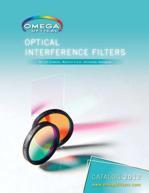
<strong>optical</strong><br />
<strong>interference</strong> <strong>filters</strong><br />
For Life Sciences, Machine Vision, Astronomy, Aerospace<br />
Catalog 2012<br />
www.omega<strong>filters</strong>.com
table of contents<br />
Introduction................................................................................................................ 4<br />
About Us.................................................................................................................... 5<br />
Intellectual Property................................................................................................... 9<br />
Research & Development.......................................................................................... 10<br />
Photonics Teaching Kit.............................................................................................. 11<br />
Descriptions & Nomenclature.................................................................................... 12<br />
Coating Technology................................................................................................... 14<br />
Filter Design............................................................................................................. 21<br />
Coating Process..........................................................................................22<br />
Physical Vapor Deposition Coatings.............................................................22<br />
Crystal Monitors Small Crystals....................................................................22<br />
Optical Monitoring.......................................................................................23<br />
The Quarter-Wave Stack Reflector...............................................................23<br />
Multi-Cavity Passband Coating....................................................................23<br />
Anti-Reflective Coatings...............................................................................24<br />
Partial Reflector..........................................................................................24<br />
Dielectric/Metal Partial Reflector and Neutral Density Metal Filters...............24<br />
Surface Coatings.........................................................................................24<br />
Dielectric Coatings......................................................................................24<br />
Extended Attenuation..................................................................................25<br />
Signal-to-Noise............................................................................................25<br />
Filter Orientation.........................................................................................25<br />
Excessive Light Energy................................................................................26<br />
Angle of Incidence and Polarization.............................................................26<br />
System Speed.............................................................................................26<br />
Temperature Effects....................................................................................27<br />
Transmittance and Optical Density...............................................................27<br />
Transmitted Wavefront Distortion.................................................................28<br />
Image Quality Filters....................................................................................28<br />
Types of Anti-Reflective Treatments and When to Use Them........................................ 29<br />
Filter Design Considerations and Your Light Source.................................................... 33<br />
Optical Interference Filters for Applications Using a LED Light Source......................... 35<br />
Measuring Transmitted Wavefront Distortion............................................................... 36<br />
Stock and Standard Products – Quick Reference Table............................................... 39<br />
Analytical Filters....................................................................................................... 44<br />
Astronomy Filters...................................................................................................... 45<br />
Amateur Astronomy Filters......................................................................................... 48<br />
Bandpass Filters....................................................................................................... 49<br />
Clinical Chemistry and Biomedical Instrumentation Filters.......................................... 53<br />
Laser Diode Clean-Up Filters..................................................................................... 54<br />
Laser Edge Longpass Filters...................................................................................... 55<br />
2<br />
For current product listings, specifications, and pricing:<br />
www.omega<strong>filters</strong>.com • sales@omega<strong>filters</strong>.com<br />
1.866.488.1064 (toll free within USA only) • +1.802.254.2690 (outside USA)
table of contents<br />
Laser Line Filters................................................................................................. 57-60<br />
Laser Rejection Filters.............................................................................................. 58<br />
Machine Vision Filters.............................................................................................. 61<br />
3 rd Millennium Filters................................................................................................ 62<br />
Photolithography Filters............................................................................................ 64<br />
UV Capabilities........................................................................................................ 65<br />
Fluorescence Filters Reference Table......................................................................... 66<br />
Fluorescence Filter Sets Reference Table................................................................... 68<br />
QuantaMAX and Standard Filters for Fluorescence – Application Note.......................... 69<br />
QuantaMAX Stock – Fluorescence Filters................................................................... 72<br />
Standard – Fluorescence Filters................................................................................. 73<br />
Multi-Band Filters..................................................................................................... 77<br />
FISH and M-FISH Filters............................................................................................ 79<br />
FISH and M-FISH <strong>Imaging</strong> – Application Note............................................................. 81<br />
Flow Cytometry Filters.......................................................................................... 85-87<br />
Flow Cytometry – Application Note............................................................................. 85<br />
FRET Filters.............................................................................................................. 88<br />
FRET – Application Note............................................................................................ 89<br />
Pinkel Filters............................................................................................................ 91<br />
Quantum Dot Filters................................................................................................... 93<br />
Sedat Filters............................................................................................................. 95<br />
Ratio <strong>Imaging</strong> Filters................................................................................................. 96<br />
IR Blocking and IR-DIC Filters.................................................................................... 96<br />
Polarizing Filters...................................................................................................... 96<br />
Neutral Density (ND) Filters....................................................................................... 97<br />
Beamsplitters & Mirrors............................................................................................ 97<br />
Multi-Photon Filters.................................................................................................. 97<br />
Fluorescence Reference Slides.................................................................................. 97<br />
Microscope Filter Holders......................................................................................... 98<br />
Optimize Your System with the Right Filter Set – Application Note............................... 99<br />
Figure of Merit........................................................................................................ 103<br />
Typical Epi-Fluorescence Configuration.................................................................... 104<br />
Fluorophore Reference Chart................................................................................... 105<br />
Emission Color Chart............................................................................................... 108<br />
Light Sources and Detector Reference Charts........................................................... 109<br />
Glossary................................................................................................................. 110<br />
Frequently Asked Questions & Answers.................................................................... 112<br />
Cleaning Optical Interference Filters........................................................................ 113<br />
Online Tools........................................................................................................... 114<br />
General Information................................................................................................ 115<br />
For current product listings, specifications, and pricing:<br />
www.omega<strong>filters</strong>.com • sales@omega<strong>filters</strong>.com<br />
1.866.488.1064 (toll free within USA only) • +1.802.254.2690 (outside USA)<br />
3
introduction<br />
Founded in 1969 by<br />
Robert Johnson D. Sc.,<br />
President and Technical<br />
Director, Omega Optical is a<br />
leader in photonics, exploring new areas with fresh ideas, an<br />
eager team, and the latest technology to produce the best in<br />
<strong>optical</strong> <strong>interference</strong> <strong>filters</strong>.<br />
Our products encompass many markets including; Industrial,<br />
Commercial, Life Science, Clinical, Astronomy (amateur and<br />
professional), as well as Defense and Aerospace. We design<br />
and produce the most diverse offering of <strong>interference</strong> <strong>filters</strong> in<br />
the industry. With over 40 years of experience partnering with<br />
researchers and instrument designers to meet their requirements,<br />
we have the experience you need. Along with our experience, we<br />
bring a corporate commitment to cooperatively explore, understand<br />
and ultimately refine solutions. This support originates with our<br />
team of Scientists, Engineers, and Industry experts from various<br />
scientific fields. We want to be your partner on every project...<br />
challenging or simple. Our guiding philosophy has always been to<br />
find solutions. If you need us, call. We will be happy to assist. Toll<br />
free within the U.S. 866-488-1064 or +1-802-254-2690, sales@<br />
omega<strong>filters</strong>.com<br />
Our headquarters resides on the Delta Campus in Brattleboro<br />
Vermont USA. We encourage you to visit! Our location is in the<br />
heart of the New England business community, conveniently<br />
located off Interstate 91; a two-hour drive from Albany New York,<br />
Boston Massachusetts and Hartford Connecticut.<br />
If you are currently a customer of Omega<br />
Optical, thank you!<br />
If you are new to Omega Optical,<br />
we look forward to working with you.<br />
This catalog is representative of only a small portion of products we<br />
have to offer. The <strong>filters</strong> within are stock (off-the-shelf) or standard<br />
(common specifications that are typical of industry standards).<br />
What’s unique, and not represented in this catalog, is our ability<br />
to provide custom solutions in a reasonable time frame at typical<br />
catalog prices from our component inventory. Contact your sales<br />
representative, or use our online tool, for your filter<br />
solution.<br />
Original Equipment Developers and<br />
Manufacturers<br />
Our expertise not only lies in the design and manufacturing<br />
of <strong>optical</strong> coatings, but in the support we can offer you in the<br />
development phase of your project. Based on your input, our<br />
engineering team will design a cost effective solution for the life<br />
cycle of your instrument. We urge you to contact us in the early<br />
development stage of your project. Our goal is to assist you in<br />
finding a solution that will achieve maximum system efficiency at<br />
the lowest cost. We will work closely with you through all steps,<br />
proof-of-concept, bread-boarding and prototyping to ensure the<br />
development of an <strong>optical</strong> solution that is consistent with your<br />
expectations.<br />
We regard our relationship with you as a long-term partnership.<br />
Our support will continue into the production phase of your project.<br />
Research Scientists and Engineers<br />
Whether your lab or research project requires one or several<br />
<strong>interference</strong> <strong>filters</strong> we invite you to contact our technical sales<br />
team. We will assist in finding the right solution whether it is an<br />
off-the-shelf product, a semi-custom solution, or a filter custom<br />
manufactured to your requirements.<br />
Stock <strong>interference</strong> <strong>filters</strong> are available off the shelf at competitive<br />
prices.<br />
Semi-custom solutions from our extensive inventory of overstock<br />
<strong>filters</strong> or plate stock configured to your requirements can be<br />
processed and shipped to you in 5 business days.<br />
Custom solutions are specifically produced to your requirements.<br />
Our sales team will work with you to develop the most cost effective<br />
solution for your application.<br />
4<br />
For current product listings, specifications, and pricing:<br />
www.omega<strong>filters</strong>.com • sales@omega<strong>filters</strong>.com<br />
1.866.488.1064 (toll free within USA only) • +1.802.254.2690 (outside USA)
about us<br />
Collaboration<br />
In any instrument development project, collaboration is key.<br />
Involving Omega early in the system design process results in<br />
optimized filter design before the system specifications become<br />
fixed. The result is reduced costs and improved performance.<br />
For these reasons, free flow of information is critical. To protect<br />
trade secrets, we ensure confidentiality throughout the life of the<br />
project. As the process unfolds, crucial performance features are<br />
identified, proof-of-concept <strong>filters</strong> are supplied for breadboarding<br />
needs, and beta parts are produced meeting the established<br />
requirements. With the completion of the development phase,<br />
we have demonstrated and provided a manufacturing plan<br />
that can be repeatedly executed for your specified production<br />
requirements.<br />
System/Instrument Development<br />
From many years of partnership experience with the world’s leading<br />
OEMs, we have developed a comprehensive understanding of the<br />
needs of instrument developers and one of the largest ranges<br />
of capabilities and product lines in the thin-film industry. A<br />
collaborative engineering approach results in high signal-to-noise,<br />
application optimization, responsive prototyping, and rapid timeto-market<br />
cycles.<br />
Throughout the design process our engineering and sales staff<br />
works with your development team to optimize total system<br />
performance within time and budgetary guidelines.<br />
Following “proof-of-concept,” breadboarding, and prototyping, a<br />
developed design is translated into an optimized manufacturing<br />
plan for production. An effective plan takes into account<br />
performance specifications, as well as yield maximization, product<br />
uniformity, and cost targets. Projections are then used to create<br />
delivery schedules to address critical inventory requirements.<br />
Review of manufacturing plans on a regular basis results in the<br />
integration of continuous improvements for your project.<br />
Custom <strong>Solutions</strong><br />
Standard catalog products can provide a high velocity filter<br />
solution with reasonable performance and, as a result, can<br />
be used for R&D, proof-of-concept, and breadboarding. For<br />
optimum system performance and significantly reduced cost we<br />
strongly recommend collaborative engineering and customized<br />
filter solutions for your specific instrument and application.<br />
Custom Filters Overview<br />
Custom <strong>filters</strong> are available in wavelengths from 185nm in the UV<br />
to 2500nm in the IR. There are a variety of filter types including<br />
bandpass, narrowband, wideband, longpass, shortpass, edge,<br />
rejection band, beamsplitters, mirrors, and absorption glass. Filters<br />
can be manufactured to almost any physical configuration up to<br />
200mm round.<br />
Omega has developed a number of programs to service the custom<br />
filter needs and requirements of OEM instrumentation customers<br />
and researchers.<br />
Engineering Services Overview<br />
Omega Optical’s engineering services are founded on years<br />
of technical experience, proprietary software, and custom<br />
modified <strong>optical</strong> measurement instruments. Our engineers play<br />
a collaborative role in design teams, assembled to develop<br />
prototype instruments, and are experienced at optimizing system<br />
performance. For sub-assembly engineering and manufacturing,<br />
our design and manufacturing services include <strong>interference</strong> <strong>filters</strong>;<br />
<strong>optical</strong> components; and customized rings, holders, and mounting<br />
hardware. Further, the R&D group develops both new coatings,<br />
and novel applications of <strong>optical</strong> <strong>filters</strong>. These applications include<br />
biomedical scanning, pathogen detection, and photovoltaic stacks.<br />
Partnership<br />
For more than 40 years we have been the filter supplier of choice<br />
to hundreds of system manufacturers. This stands as testament to<br />
our high technical standards, the ability to produce thousands of<br />
parts to identical specifications, and timely delivery. Throughout<br />
these long-term partnerships we build your confidence to become<br />
your sole supplier. A relationship is based on intimate knowledge<br />
of your instrument, and team that leads to increased efficiencies<br />
and instrument performance over time.<br />
For current product listings, specifications, and pricing:<br />
www.omega<strong>filters</strong>.com • sales@omega<strong>filters</strong>.com<br />
1.866.488.1064 (toll free within USA only) • +1.802.254.2690 (outside USA)<br />
5
about us<br />
MARKETS & APPLICATIONS<br />
Life Science<br />
Omega Optical is a leading supplier worldwide of custom <strong>filters</strong><br />
for research, clinical, and point-of-care fluorescence based<br />
instruments and applications. We service the world’s leading<br />
system manufacturers and have developed one of the largest<br />
ranges of capabilities and product lines in the industry. Our <strong>filters</strong><br />
are used extensively in research and clinical applications in the<br />
biomedical, biotech, and drug discovery markets, with <strong>filters</strong> being<br />
engineered into the next generation of life science instruments.<br />
Representative Markets include:<br />
• Microplate and MicroArray Readers and Scanners<br />
• DNA Sequencers and Analyzers<br />
• Lab-on-a-Chip and Gene Chip Readers<br />
• Flow Cytometers and Cell Sorters<br />
• Real-time PCR Analyzers<br />
• Gel Documentation Readers<br />
• Scanners and <strong>Imaging</strong> Systems<br />
• High-Throughput and High-Content Systems<br />
• Genomics and Proteomics Systems<br />
• Fluorescence and Raman Spectroscopes<br />
• Confocal and Multiphoton Microscopes<br />
Fluorescence Microscopy<br />
We have played a pioneering role in the developments of filter<br />
technology for fluorescence microscopy and are one of the world’s<br />
leading suppliers in this market. We offer an extensive product line<br />
of dye-specific filter sets for single and multi-label fluorescence<br />
microscopy applications and work collaboratively with researchers,<br />
labs, and microscope manufacturers on the development of sets<br />
for new cutting-edge applications. Filter sets, individual <strong>filters</strong>, and<br />
holders are available for all major microscope manufacturers and<br />
models, including Leica, Nikon, Olympus, and Zeiss.<br />
Representative Applications:<br />
• Confocal<br />
• Multiphoton<br />
• Fluorescent Proteins<br />
• Quantum Dots<br />
• M-FISH<br />
• FRET<br />
• Ratio <strong>Imaging</strong><br />
• Caged Compounds<br />
Astronomy/Aerospace<br />
We are one of the most respected suppliers of <strong>optical</strong> <strong>filters</strong> in the<br />
world for space-based and observational astronomy and aerospace<br />
projects. We work in collaboration with NASA, JPL, AURA,<br />
ESO as well as a variety of international consortia, government<br />
agencies, and researchers. We have years of experience designing<br />
and manufacturing custom and standard prescription <strong>filters</strong> to<br />
the highest imaging quality standards. Our capabilities include<br />
solar observation, photometric sets encompassing Bessel, SDSS,<br />
Stromgren, and other <strong>filters</strong>.<br />
Our <strong>filters</strong> have helped probe deep space as part of the Hubble<br />
Space Telescope’s Widefield Planetary Camera and served as the<br />
eyes of the Mars Exploration Rovers. See pages 45-47.<br />
Photolithography<br />
Our i-line <strong>filters</strong> for semiconductor lithographic tools, such as LSI<br />
and LCD Steppers, surpass the performance of standard OEM <strong>filters</strong>.<br />
These high performance and environmentally stable bandpass <strong>filters</strong><br />
resolve monochromatic wavelengths from the high power Metal<br />
Halide/Mercury lamps reaching the photomask substrate, so that<br />
optimum resolution is achievable. We also supply superior maskaligner<br />
<strong>filters</strong> for the lithographic process. See page 64.<br />
Color <strong>Imaging</strong><br />
Color imaging systems benefit from the use of precision <strong>optical</strong><br />
<strong>filters</strong> which control the spectral properties of light and color<br />
separation to exacting tolerances. Image capture and reproduction<br />
are enhanced when the prime colors of light are precisely separated<br />
or trimmed on capture and then recombined before reaching the<br />
detector. Image quality and performance improves when system<br />
optics deliver precise color separation, high color signal-to-noise,<br />
and a wide dynamic range. Omega offers a variety of products to<br />
this market, including a patented color enhancement filter, as well<br />
as color separation, color correction, and color temperature <strong>filters</strong>.<br />
See pages 16-18. For detailed product specifications, please visit<br />
our website.<br />
Raman Spectroscopy<br />
Raman spectroscopy is employed in many applications, including<br />
mineralogy, pharmacology, corrosion studies, analysis of<br />
semiconductors and catalysts, in situ measurements on biological<br />
systems, and single molecule detection. While this technique<br />
provides positive material identification of unknown specimens to a<br />
degree that is unmatched by other spectroscopies, it also requires<br />
rigorous filter specifications for the detection and resolution of<br />
narrow bands of light with very low intensity and minimal frequency<br />
shift relative to the source. To meet these requirements Omega<br />
supplies a variety of products, including laser line <strong>filters</strong> for<br />
“cleaning up” laser signals and high performance edge <strong>filters</strong> that<br />
out-perform holographic notch <strong>filters</strong>.<br />
Industrial Instrumentation<br />
Industrial instrumentation requires precision <strong>filters</strong> for control,<br />
analysis, and detection. We provide a wide variety of filter solutions<br />
for various industrial applications that includes some of the following:<br />
Process Control and Monitoring; End Point Determination; Closed<br />
Loop and Real-time Instruments; Materials Analysis; and others.<br />
6<br />
For current product listings, specifications, and pricing:<br />
www.omega<strong>filters</strong>.com • sales@omega<strong>filters</strong>.com<br />
1.866.488.1064 (toll free within USA only) • +1.802.254.2690 (outside USA)
Capabilities<br />
Design<br />
• Thin Film DesignSoftware<br />
• TF CALC<br />
• Optilayer (Leybold)<br />
• FilmStar<br />
• The Essential Macleod<br />
• Optical Raytrace Software<br />
• Mechanical CAD Packages<br />
• Instrumentation Interface Tools such as LabView and Python<br />
• Chemical modeling with Hyperchem<br />
Optical Testing<br />
• Spectrally Resolved Measurements of Transmission,<br />
Reflectance, and Absorption:<br />
- Multiple Spectrophotometers<br />
- A Spectrophotometric Mapping System for large substrates<br />
- Attachments for off-axis R&T Measurements including<br />
Polarization Effects<br />
• Optical Density Measurements:<br />
- Visible Laser Radiometers<br />
- NIR Laser Radiometers<br />
• Surface Quality (total wavelength distortion, flatness,<br />
wedge, roughness, and pinhole density):<br />
- Broadband Achromatic Twyman-Green Interferometer<br />
- Shack-Hartmann Wavefront Tester<br />
- Autocollimator<br />
- Integrating Sphere<br />
- Angle Resolved Scatter Test Set<br />
- Differential Interference Contrast (DIC) Microscopy<br />
• Fiber Optic Testing at Visible and Near Infrared<br />
Wavelengths<br />
• Fluorescence and Autofluorescence:<br />
- Spectrofluorimeters<br />
- Multispectral Fluorescence <strong>Imaging</strong><br />
• Environmental Testing:<br />
- Low and High Temperature Testing<br />
- Humidity Testing<br />
• Photovoltaic Testing:<br />
- IV/CV Profiles<br />
- Kelvin Probe<br />
Coating Systems<br />
Of our numerous vacuum coating systems, we have the capability<br />
for coating a full range of dielectric metal and insulation materials.<br />
We achieve physical vapor deposition (PVD) (evaporated coatings)<br />
with or without ion assist (IAD) of refractory oxides, as well as<br />
thermal evaporation of metal salts and metal alloys. All of our<br />
coating systems have been designed to enhance our proprietary<br />
coating processes.<br />
Optical Fabrication<br />
• CNC Metal Machining<br />
• Scribe & Break<br />
• Laser Scribing, Welding, and Ablation<br />
Our glass fabrication shop is equipped with a Speedfam grind and<br />
polish machine, along with diamond-tooled machines, including<br />
CNC drills, shapers, and saws.<br />
Scribe and break<br />
For the best competitive price and reduced lead times, our<br />
scribe and break capabilities make use of a unique diamond<br />
wheel cutting technology. Scribe and break is a clean process<br />
that does not require oils, blocking waxes, or exposure to heat.<br />
Additionally there is significantly less handling of the <strong>optical</strong> coated<br />
plate. Fundamentally, we scribe the exact shape of the finished<br />
product penetrating through the <strong>optical</strong> coating on the substrate<br />
material. Scribes may be generated with a depth up to 90% of<br />
the material thickness greatly reducing a required breaking force.<br />
This technology is useful over a wide range of substrate material<br />
thicknesses from .05 mm to upwards of 3 mm.<br />
The end results of this capability include consistent outcome,<br />
higher yield, increased edge strength, rapid dicing, and a<br />
reduction of potential edge chipping and cracks. Cutting accuracy<br />
is very high enabling the production of very small finished<br />
product. Additionally, the ability to hold very tight tolerances as<br />
well as produce more unusual, irregular, or non-standard shapes<br />
becomes available.<br />
Optical Assembly<br />
Our fully equipped machine shop has the capability of producing<br />
jigs and fixtures along with a variety of custom filter rings, wheels,<br />
and holders.<br />
Filter components are cleaned ultrasonically and assembled under<br />
laminar flow hoods.<br />
Glass Substrates<br />
We stock nearly all scientific glasses, fused silica, and specialty<br />
glass substrates.<br />
For current product listings, specifications, and pricing:<br />
www.omega<strong>filters</strong>.com • sales@omega<strong>filters</strong>.com<br />
1.866.488.1064 (toll free within USA only) • +1.802.254.2690 (outside USA)<br />
7
about us<br />
Quality Assurance, Testing, and Certification<br />
The Quality Management System of Omega Optical is modeled<br />
on the foundations of the ISO 9001:2000 quality management<br />
standards.<br />
The overall company goal is to enhance product quality with<br />
standardized and systematic methods.<br />
Filters are tested and evaluated at every stage of production.<br />
Spectrometers and <strong>optical</strong> measuring instruments are tested,<br />
controlled, calibrated, and maintained to meet the requirements<br />
of our quality system.<br />
• Filter surface durability and quality is in accordance with MIL-<br />
C-48497A.<br />
• Environmental durability, testing documentation and certification<br />
can be provided at the customer’s request.<br />
• When appropriate, we follow sampling procedures defined by<br />
MIL-STD-105E.<br />
• REACH, PFOS and RoHS statements can be found on our<br />
website.<br />
We have an in-house capability for making automated spatiallyresolved<br />
spectral measurements of coated plates up to 200 mm<br />
in diameter. These high-resolution spatial-spectral measurements<br />
quantify in-spec regions of each plate; the result is fed directly<br />
to downstream part<br />
configuring operations.<br />
Plate regions that do<br />
not meet spec are<br />
inventoried for future<br />
sale requiring no<br />
"Omega Optical will deliver quality<br />
product on time, which meets or<br />
exceeds customer expectations,<br />
through continual improvement<br />
and effective partnerships with<br />
suppliers and customers."<br />
additional spectral<br />
measurements. This<br />
one-stop measurement of the entire plate eliminates redundant<br />
measurement and drastically increases efficiency both in plate<br />
utilization to meet immediate orders and future data mining<br />
operations to locate surplus stock.<br />
Personnel<br />
A technical staff of engineers, industry specialists, scientists, PhDs,<br />
and technicians combine years of experience, a broad knowledge<br />
base, and a command of the craft involved in producing precision<br />
<strong>interference</strong> <strong>filters</strong>.<br />
8<br />
For current product listings, specifications, and pricing:<br />
www.omega<strong>filters</strong>.com • sales@omega<strong>filters</strong>.com<br />
1.866.488.1064 (toll free within USA only) • +1.802.254.2690 (outside USA)
intellectual property<br />
3 RD Millennium <strong>filters</strong> are available as high-performance commodity <strong>filters</strong> for OEM instrumentation or for research and lab applications.<br />
Patent #6,918,673<br />
SpectraPlus for accurate hue, enhanced saturation, increased color signal-to-noise, and a resulting improved Modulation Transfer<br />
Function (MTF). SpectraPLUS coating technology is the deposition of multiple layers of thin film coatings on glass and acrylic lenses for the<br />
enhancement of viewing color images to address two primary areas. This technology benefits color imaging systems as well as applications<br />
where the eye is the detector. The coating allows transmission of the three bands of pure color—red, green, and blue—while blocking those<br />
intermediate wavelengths that distort the perception or recording of color. It also eliminates wavelengths in the ultraviolet and near infrared<br />
which are detrimental to an accurate color rendering and visual record. Patent #5,646,781<br />
Multispectral stereographic display system Patent pending<br />
Multispectral stereographic display system with additive and subtractive techniques Patent pending<br />
ALPHA coating technology<br />
Omega Optical’s proprietary ALPHA coating technology for extremely steep slopes resulting in precise edge location, the ability to place<br />
transmission and rejection regions exceptionally close together, and high attenuation between the passband and the rejection band. ALPHA<br />
coating technology pushes the limits of fluorescence and Raman signal detection, producing extremely high signal-to-noise and brighter<br />
images for demanding imaging applications.<br />
Multi-band Technology<br />
Omega Optical holds the 1992 patent on all <strong>filters</strong> with multiple passband and rejection bands, including dual-band, triple-band, and quadband<br />
<strong>filters</strong>. These filter types have usefulness in a variety of life science applications for visualizing multiple fluorophores simultaneously, as<br />
well as in a range of other applications. Patent #5,173,808<br />
Multispectral <strong>Imaging</strong><br />
Omega Optical licenses and owns IP related to high speed systems for multispectral imaging of tissue. Our <strong>filters</strong> are used within a device,<br />
which has many applications in the biomedical optics field.<br />
Organic Photovoltaics<br />
Omega Optical owns IP related to organic photovoltaic devices. Our thin film expertise is leveraged to fabricate these devices, which have<br />
significant potential in the alternative energy field.<br />
For current product listings, specifications, and pricing:<br />
www.omega<strong>filters</strong>.com • sales@omega<strong>filters</strong>.com<br />
1.866.488.1064 (toll free within USA only) • +1.802.254.2690 (outside USA)<br />
9
esearch & development<br />
We embrace a vision that goes beyond designing and fabricating state-of-the-art <strong>interference</strong> <strong>filters</strong>. Most bandpass,<br />
longpass and shortpass <strong>interference</strong> <strong>filters</strong> are based on the real component of the refractive index of dielectric materials.<br />
At Omega Optical, our R&D team is developing novel thin films where the refractive index has both a real and a complex component.<br />
Examples include semiconductors (such as p-type organics, & n-<br />
type organics), and transparent conductive oxides (such as indiumtin-oxide,<br />
& aluminum-zinc-oxide). The complex component of the<br />
index of these materials can lead to absorption and/or reflectance<br />
in specific spectral bands. In addition, we are depositing dielectric<br />
stacks on unusual substrates, such as the tips of <strong>optical</strong> fibers. Our<br />
team includes expertise in <strong>optical</strong> sciences, physics, chemistry,<br />
materials science, electrical engineering, mechanical engineering,<br />
bioengineering, and software (3 PhDs, 1 MS, and 3 undergraduate<br />
degrees). We focus on leveraging our expertise to create products<br />
that rely on advanced thin films. Currently, we are addressing two<br />
key areas: solar conversion and multispectral scanning.<br />
Omega Optical’s Solar Conversion program employs organic<br />
thin film absorbers, and electrodes composed of transparent<br />
conductive oxides. Our solar goal centers on creating a solar<br />
cell prototype enabling significant reductions in module cost and<br />
significant increases in module efficiency, leading to acceptable<br />
payback times. This objective will be addressed by integrating<br />
photovoltaic (PV) and/or photothermal (PT) collection mechanisms<br />
while avoiding both scarce and toxic materials. The potential of low<br />
cost organic PV materials has not been widely realized because of<br />
low efficiency relating to electronic mobility and excitonic diffusion<br />
lengths. We believe that organic thin film deposition parameters<br />
can be adjusted to optimize these parameters and maximize PV<br />
efficiency. Further, organic materials can be configured to harvest<br />
multiple spectral bands. We plan to separate these bands via costeffective<br />
spectral splitting for efficient collection by the appropriate<br />
material. Ultimately, we plan to integrate our designs with residential<br />
and commercial building materials. Targeted products include<br />
semitransparent solar windows.<br />
This effort has been co-funded by Omega Optical Inc. and<br />
the United States Department of Energy.<br />
Left to Right: Dr. Robert Johnson – President and Technical Director -<br />
Omega Optical; Patrick Leahy - United States Senator, Vermont; Dr. Gary<br />
Carver - Director of R&D - Omega Optical.<br />
fast fiber based spectrometer. This project leverages several of our<br />
<strong>interference</strong> filter designs deployed in the fluorescence market<br />
since the last 1980’s.<br />
Ultimately, biomedical researchers will use this new technology to<br />
catalog extensive libraries of multispectral images showing tumor<br />
angiogenesis and subsequent metastases. These enhanced libraries<br />
will lead to several applications in pathology labs, oncology<br />
labs, and clinics. Clinicians will use the technology to take <strong>optical</strong><br />
biopsies, perform treatments, and monitor long-term results.<br />
Patients will have access to real-time diagnosis and treatment. Surgeons<br />
will be able to optimize surgical margins, extending the lives<br />
of many cancer victims. Targeted products include disease-specific<br />
fiber cassettes for use in customized confocal scanning systems.<br />
This project is funded by a Phase II SBIR grant from the National<br />
Cancer Institute within the National Institutes of Health in Bethesda<br />
Maryland USA.<br />
Omega’s Multispectral scanning program project integrates<br />
<strong>interference</strong> <strong>filters</strong>, fiber Bragg gratings, and <strong>optical</strong> fibers. This<br />
fiber based design enables high speed spectral management,<br />
providing medical diagnoses in real-time. Our biomedical goal<br />
centers on developing a high-speed fiber optic based <strong>optical</strong><br />
spectrum analyzer (OSA) that can enable real time multispectral<br />
imaging of cancer at the cellular level. Existing technologies have<br />
not combined sufficient spatial, spectral, and temporal resolution<br />
in one instrument. Standard spectrometer acquisition speeds are<br />
not fast enough to generate multispectral data at rates that avoid<br />
spatial impairments due to the movements of living biological<br />
samples. The central innovation in this effort is that spectra can<br />
be acquired for each pixel in a confocal spatial scan by using our<br />
Technical Outgrowths<br />
The above projects are generating results that are finding additional<br />
applications including customized transparent conductive oxides,<br />
and thin film spectral blocking layers with low wavefront distortion.<br />
We also see potential in applications in such as food & water testing,<br />
pharmaceutical product screening, multispectral microscopy,<br />
and flow cytometry. Further, we have developed a suite of <strong>optical</strong><br />
testing capabilities that are available on a consulting basis.<br />
Optical solutions can be employed in a multitude of applications<br />
from creating alternative energy solutions to new methods for treating<br />
cancer. We encourage you to inquire regarding other novel <strong>optical</strong><br />
methods that will improve the quality of life throughout the world.<br />
10<br />
For current product listings, specifications, and pricing:<br />
www.omega<strong>filters</strong>.com • sales@omega<strong>filters</strong>.com<br />
1.866.488.1064 (toll free within USA only) • +1.802.254.2690 (outside USA)
photonics teaching kit<br />
Involved in the design, fabrication, or production of optics or<br />
<strong>optical</strong> devices?<br />
Teaching or learning about photonics?<br />
Learn principles of photonics and how the interaction of<br />
light with matter plays a role in our everyday lives.<br />
Get a head-start on the exciting careers of tomorrow.<br />
Hands-on labs examine a wide variety of topics within<br />
photonics.<br />
One Photonics Kit accommodates 6 small groups.<br />
Photonics now and in the future begins with the educational systems of our society.<br />
The Omega Optical Photonics Kit – Teach Photonics!<br />
For Science Educators – Help students to explore the environment around them, discovering the principles on the interactions of light<br />
and matter and how to manipulate these interactions.<br />
For Professionals – Finding workers with a fundamental understanding of <strong>optical</strong> principles is a challenge. The need for cost-effective<br />
employee training and education that delivers real-time benefits is a priority as organizations continuously adapt to changing marketplaces,<br />
and external competition.<br />
Our Photonics Teaching kit includes 12 lab activities based on various topics within the field of photonics including solar cells, reflection,<br />
refraction, wave <strong>interference</strong>, LEDs, light detection, complementary colors, fluorescence, and phosphorescence.<br />
The comprehensive labs are organized and supported<br />
with all required hardware for the following:<br />
wave/particle duality of light<br />
interactions of light and matter including scattering, reflection,<br />
refraction, fluorescence and phosphorescence<br />
relationship between the electronic structure of an atom or<br />
molecule and its emission and absorption spectra<br />
how light can be used to encode information by changing<br />
intensity, spectral characteristics or polarization<br />
how information about the structure of a molecule can be<br />
elucidated using spectroscopy<br />
principles behind <strong>optical</strong> computing<br />
human and animal perception of color<br />
principles behind the operation of LEDs, solar cells, and fiber<br />
optic cables are explored<br />
For current product listings, specifications, and pricing:<br />
www.omega<strong>filters</strong>.com • sales@omega<strong>filters</strong>.com<br />
1.866.488.1064 (toll free within USA only) • +1.802.254.2690 (outside USA)<br />
11
Descriptions & Nomenclature<br />
Bandpass Filters<br />
Dichroic Filters<br />
555XX30<br />
CWL (center wavelength) Filter Design FWHM/Bandwidth<br />
3RD550-580<br />
Cut-on Cut-off<br />
505DRLP<br />
Cut-on Filter Design<br />
675DCSPXR<br />
Cut-off Filter Design<br />
Note: Full Width Half Max (FWHM) is defined<br />
by the region of the passband where the transmission<br />
of the filter is 50% of the maximum transmission.<br />
Filter Design – Our nomenclature and descriptors define the<br />
performance characteristics of filter designs.<br />
• BP – Bandpass filter: Bandpass <strong>filters</strong> transmit light within a<br />
defined spectral band. Coating designs range from 2 to 6 cavities.<br />
• QM – QuantaMAX: Surface coated, single substrate designs<br />
provide steep edges, very high transmission and minimal<br />
registration shift.<br />
• 3RD – 3 RD Millennium: Filters are manufactured using<br />
proprietary ALPHA coating technology and Omega’s patented,<br />
hermetic assembly, and defined by the critical cut-on and cut-off<br />
requirement.<br />
• AF – ALPHA Filter: Alpha filter designs are manufactured using<br />
Omega’s proprietary technology resulting in extremely steep<br />
edges, precise edge placement, and theoretical attenuation<br />
>OD10. Defined by the critical cut-on and cut-off requirement.<br />
• DF – Discriminating Filter: These filter designs have 6 or more<br />
interfering cavities, resulting in a rectangular bandpass shape,<br />
very steep edges, and very deep blocking up to <strong>optical</strong> density<br />
(OD) 6 outside the passband.<br />
• WB – Wideband Filter: Wideband <strong>filters</strong> are 4 & 5 cavity<br />
designs with FWHM greater than 30nm, up to several hundred<br />
nanometers.<br />
• NB – Narrowband: Narrowband <strong>filters</strong> are 2-cavity designs with<br />
FWHM typically between 0.2 and 8nm.<br />
Note: Cut-on or cut-off wavelength is defined<br />
as the wavelength at which the dichroic is at 50%<br />
of its maximum transmission.<br />
Filter Design – Dichroics are <strong>filters</strong> that highly reflect one specified<br />
spectral region while optimally transmitting another. These <strong>filters</strong><br />
are often used at non-normal angles of incidence, typically 45<br />
degrees.<br />
• DC – Dichroic: These <strong>filters</strong> provide wide regions of both<br />
transmission and reflection, exhibiting a high degree of<br />
polarization along with a somewhat shallow transition slope.<br />
• DR – Dichroic Reflector: These designs provide a steeper<br />
slope than typical DC <strong>filters</strong>, low polarization, a wide range of<br />
transmission and a limited region of reflection.<br />
• DCXR – Dichroic Extended Reflector: A design that provides<br />
extended reflection regions.<br />
• DCSP / DCLP / DRSP / DRLP: These designations dictate those<br />
portions of the spectrum that will be transmitted and reflected.<br />
The “SP” (shortpass) nomenclature means the filter will be<br />
transmitting wavelengths below the defined cut-off region. The<br />
“LP” (longpass) nomenclature defines the region of transmission<br />
as wavelengths above the defined cut-on region.<br />
12<br />
For current product listings, specifications, and pricing:<br />
www.omega<strong>filters</strong>.com • sales@omega<strong>filters</strong>.com<br />
1.866.488.1064 (toll free within USA only) • +1.802.254.2690 (outside USA)
Longpass & Shortpass Filters<br />
515ALP<br />
Cut-on Filter Design<br />
680 ASP<br />
Cut-off Filter Design<br />
3RD 650LP<br />
Filter Design Cut-on<br />
Note: Cut-on or cut-off wavelength is defined<br />
as the wavelength at which the filter is at 50%<br />
of its maximum transmission.<br />
Filter Product Line Codes<br />
XA – Analytical Filters<br />
XB – Bandpass Filters<br />
XC – Microscope Filter Holders<br />
XCC – Clinical Chemistry<br />
XCY – Flow Cytometry Filters<br />
XF – Fluorescence Filters<br />
XL – Laser Line Filters (not blocked)<br />
XLD – Laser Diode Clean-up<br />
XLK – Laser Line Filters (fully blocked)<br />
XLL – Laser Line Filters<br />
XMV – Machine Vision<br />
XND – Neutral Density Filters<br />
XRLP – Raman Longpass Filters<br />
XUV – UV Filters<br />
• LP – Longpass: These <strong>filters</strong> transmit wavelengths longer than<br />
the cut-on and reflect a range of wavelengths shorter than the<br />
cut-on.<br />
• SP – Shortpass: These <strong>filters</strong> transmit wavelengths shorter than<br />
the cut-off and reflect a range of wavelengths longer than the<br />
cut-off.<br />
Multi-band Filters<br />
• DB – Dual Band: Filters are designed to have two passbands<br />
and two rejection bands.<br />
• TB – Triple Band: Filters are designed to have three passbands<br />
and three rejection bands.<br />
• QB – Quad Band: Filters are designed to have four passbands<br />
and four rejection bands.<br />
For current product listings, specifications, and pricing:<br />
www.omega<strong>filters</strong>.com • sales@omega<strong>filters</strong>.com<br />
1.866.488.1064 (toll free within USA only) • +1.802.254.2690 (outside USA)<br />
13
Coating Technology<br />
QuantaMAX – for high performance <strong>interference</strong><br />
<strong>filters</strong><br />
Outstanding spectral characteristics on a wide variety of<br />
substrate materials utilizing our state-of-the-art deposition<br />
technology, Dual Magnetron Reactive Sputtering (DMRS).<br />
Transmission<br />
For today’s most sensitive instruments,<br />
QuantaMAX <strong>optical</strong> coatings provide<br />
exceptional throughput. As seen in Figure 1, a<br />
standard 510-560 <strong>interference</strong> filter achieves<br />
transmission in excess of 97%. Combined with<br />
deep out of band attenuation, QuantaMAX<br />
<strong>optical</strong> coatings make every photon count.<br />
Transmission (%)<br />
Wavelength (nm)<br />
Optical Density<br />
For many applications, the out of band<br />
blocking at the detector is as important as the<br />
overall transmission. Figure 2 shows the out<br />
of band blocking from 300-1000nm and the<br />
<strong>optical</strong> density average of > 6.0. A filter with<br />
these characteristics operating in a system<br />
with an ideal light source and detector could<br />
be expected to have a signal/noise ratio of<br />
exceeding 10,000:1, while collecting all<br />
available signal.<br />
Optical Density<br />
Wavelength (nm)<br />
14<br />
For current product listings, specifications, and pricing:<br />
www.omega<strong>filters</strong>.com • sales@omega<strong>filters</strong>.com<br />
1.866.488.1064 (toll free within USA only) • +1.802.254.2690 (outside USA)
Lot to Lot Reproducibility<br />
With the Dual Magnetron Reactive Sputtering<br />
(DMRS) process, QuantaMAX <strong>optical</strong> coatings<br />
employ the latest methods in <strong>optical</strong> thin-film<br />
design and deposition control. Utilizing the<br />
DMRS technology we achieve very precise<br />
individual layer thickness, along with forward and<br />
backward “proof-reading” of layer execution,<br />
leading to a high degree of predictability and<br />
reproducibility lot-to-lot. As depicted in Figure 3,<br />
the edge of the 650-670 bandpass filter varies<br />
only 1 nm in either the cut-on or cut-off edges<br />
across a sampling of 5 individual deposition lots.<br />
Transmission Transmission (%) Transmission (%) (%)<br />
Wavelength (nm)<br />
Wavelength (nm)<br />
Wavelength (nm)<br />
Minimized Transmission<br />
Band Distortion<br />
The ability to precisely deposit a layer of coating<br />
material of optimized <strong>optical</strong> thicknesses in<br />
a stable and highly reproducible manner<br />
throughout the deposition cycle provides<br />
excellent transmission characteristics with<br />
minimal pass-band rippling. Figure 4 and 5<br />
show the typical performance of long-pass and<br />
short-pass <strong>interference</strong> <strong>filters</strong>.<br />
Transmission Transmission (%) (%) (%)<br />
Wavelength (nm)<br />
Wavelength (nm)<br />
Wavelength (nm)<br />
Transmission (%) (%)<br />
Wavelength Wavelength (nm) (nm)<br />
Wavelength (nm)<br />
For current product listings, specifications, and pricing:<br />
www.omega<strong>filters</strong>.com • sales@omega<strong>filters</strong>.com<br />
1.866.488.1064 (toll free within USA only) • +1.802.254.2690 (outside USA)<br />
15
Coating Technology<br />
Viewing Enhancement Coatings<br />
SpectraPlus for accurate hue, enhanced saturation, increased<br />
color signal-to-noise, and a resulting improved Modulation Transfer<br />
Function (MTF). SpectraPLUS coating technology is the deposition<br />
of multiple layers of thin film coatings on glass and acrylic lenses for<br />
the enhancement of viewing color images to address two primary<br />
areas. This technology benefits color imaging systems as well<br />
as applications where the eye is the detector. The coating allows<br />
transmission of the three bands of pure color—red, green, and<br />
blue—while blocking those intermediate wavelengths that distort the<br />
perception or recording of color. It also eliminates wavelengths in the<br />
ultraviolet and near infrared which are detrimental to an accurate<br />
color rendering and visual record.<br />
Two of the more recent and unique technical capabilities developed<br />
at Omega have been employed in developing these products. They<br />
offer the ability to deposit complex coatings on curved surfaces with<br />
control of the thickness distribution over the full usable aperture of<br />
the curved optic that makes these features possible. The control<br />
of thickness can be either to create uniform thickness where the<br />
normal distribution is thinner away from the center, or it can be<br />
applied and adjusted to create a thickening coating profile toward<br />
the edge to compensate for viewed angular effects that would cause<br />
band shifting.<br />
Other enhancements can be integrated into viewing systems.<br />
Coatings such as photochromics, or anti-scratch, or hydophobic<br />
can be added to produce the highest technology, and performing<br />
eyewear world-wide. Applications where these coatings can make<br />
the difference between success and failure exist everywhere that<br />
excellent vision is a benefit. Typical of these would be dentistry,<br />
surgery, sports, high speed maneuvering and viewing in poorly lite<br />
situation.<br />
Omega Optical is prepared and anxious to work closely to refine this<br />
product line to bring your offer to be the last considered.<br />
SpectraPLUS is protected by U.S. patent #5,646,781.<br />
Depth Defining ® series is a totally new approach to displaying and<br />
viewing an image with an X and Y impression as well as a clear Z<br />
element. The ultra-complex spectral function divides the visible into<br />
two visually identical white mixtures which are mutually exclusive.<br />
The left and right viewing eye see distinct images that have been<br />
projected spatially or temporally independent. The result is an image<br />
with depth that the viewer can experience with clarity.<br />
Both of these product developments open many possibilities for<br />
new areas of <strong>optical</strong> device improvement and development.<br />
Photo courtesy of Leybold Optics. Syrus Pro 1510 LION Assisted Electron<br />
Beam Custom Opthalmic Coater. Our engineers have worked closely<br />
with Leybold Optics of Germany to refine the performance of this large<br />
coating tool for the precise deposition of complex multi-layers for Image<br />
Enhancement coatings under the SpectraPlus brand.<br />
16<br />
For current product listings, specifications, and pricing:<br />
www.omega<strong>filters</strong>.com • sales@omega<strong>filters</strong>.com<br />
1.866.488.1064 (toll free within USA only) • +1.802.254.2690 (outside USA)
ColorMAX series is intended for spectral refinement with the<br />
intended purpose of improving color rendition through saturation and<br />
hue. Curved lenses are coated with a complex multi-layer coating<br />
that removes harmful UV rays, as well as IR. These coatings further<br />
eliminate the colors of light that stimulate multiple cones that result in<br />
color confusion. The final product is eyewear that forces all colors to<br />
explode from their background.<br />
We offer two ColorMAX <strong>filters</strong> with SpectraPLUS coatings; XB29 is<br />
optimized for digital imaging sensors and XB30 is optimized for the<br />
human eye and film. All <strong>filters</strong> are finished to the highest imaging<br />
quality standards and are available in stock and custom sizes.<br />
XB29 for Digital <strong>Imaging</strong> Systems and CCD based cameras blocks<br />
the crossover regions between blue/green and green/red centered at<br />
490nm and 600nm respectively. To prevent IR saturation of siliconbased<br />
sensors, the coating provides a high degree of attenuation in<br />
the near infrared region, from 750nm to 1100nm. XB29 also offers<br />
complete attenuation of ultraviolet A and B, and deep blue up to<br />
430nm.<br />
For Digital <strong>Imaging</strong> Systems:<br />
- Commercial Printing Industry:<br />
Pre-press Scanners<br />
- Machine Vision Industry:<br />
Camera and Lens Systems<br />
- Office and Home Small Equipment Industry: Desktop Scanners, Color<br />
Copiers, Digital Copiers.<br />
- Photography/Video/Film Industry:<br />
Video & Digital Cameras and Lenses, Photo Scanners<br />
- Remote Sensing: Camera Systems<br />
XB29 for Eye and Film is optimized for applications where the human<br />
eye or photographic film is the detector. Color imaging is enhanced<br />
with increased saturation, accurate hue, and improved contrast and<br />
resolution. This version of the SpectraPLUS filter has two stop band<br />
regions centered at 490nm and 580nm for blocking the prime color<br />
"crossover" wavelengths between blue/green and green/red in the<br />
visible spectrum. The XB30 offers high attenuation of ultraviolet A &<br />
B. It also attenuates the near infrared in a band centered at 725nm<br />
For Human Eye and Photographic Film Detection:<br />
- Sports Eyewear Industry: Sunglasses,<br />
Ski Goggles, Active Sports Glasses<br />
- Lighting Industry: Medical and Dental Lights, Bulb and Reflector coatings<br />
- Photography/Video/Film Industry:<br />
Camera Lens, Video, Film and Slide Projectors, Color and Black&White Film<br />
Printers, Enlarger Lens<br />
- Sports Optics Industry: Binoculars and spotting scopes, Rifle Scopes<br />
All sensors - human eye, film, and electro-<strong>optical</strong> - have limitations in<br />
how they "see" and record color. Their receptors significantly overlap,<br />
as do the wavelengths for the three prime colors of light: red, green,<br />
and blue. A photon of light from within this overlap region can leave an<br />
incorrect signal on the receptor so that a green photon, for example,<br />
can be perceived or recorded as blue or red.<br />
For current product listings, specifications, and pricing:<br />
www.omega<strong>filters</strong>.com • sales@omega<strong>filters</strong>.com<br />
1.866.488.1064 (toll free within USA only) • +1.802.254.2690 (outside USA)<br />
17
Coating Technology<br />
Transparent Conductive Oxides Overview<br />
Transparent Conductive Oxides (TCOs) are a special class of<br />
materials that exhibit both transparency and electronic conductivity<br />
simultaneously. These materials have widespread applications in<br />
flat-panel displays, thin film photovoltaics, low-e windows, and<br />
flexible electronics. The requirements of the these materials are not<br />
just limited to transparency and conductivity but also include work<br />
function, processing and patterning requirements, morphology,<br />
long term stability, lower cost and abundance of materials involved.<br />
Spectral edges can be generated with the intrinsic properties of one<br />
layer of TCOs. This happens with materials like Indium Tin Oxide<br />
(ITO) and Aluminum Zinc Oxide (AZO) that have much stronger k<br />
values in one spectral band than another band.<br />
Transmission (%)<br />
Description<br />
Currently, ITO is far superior in performance compared to other<br />
TCOs and many efforts are being made worldwide to find suitable<br />
alternatives. ITO intrinsically has high transparency in the visible<br />
and high reflectance in the infrared region. It is commonly used in<br />
LCDs and thin film photovoltaic devices. Characteristics of these<br />
materials can be widely altered with making changes in deposition<br />
parameters. These materials can be integrated with dielectrics to<br />
provide wide band IR blocking with thinner layers and low wavefront<br />
distortion.<br />
Types<br />
Addressing the wide concern about scarcity and high cost of<br />
Indium, Omega is also investigating several other Indium free<br />
TCOs, namely,<br />
• Aluminum doped Zinc Oxide<br />
• Fluorine doped Tin Oxide<br />
• Zinc Tin Oxide<br />
• Nickel Oxide and other combinations.<br />
Documentation: Spectrophotometric trace of the attenuation, cuton,<br />
and transmission regions provided. Electronic characteristics<br />
such as work function, resistivity and surface roughness are<br />
provided upon request.<br />
Figure X: Typical ITO Spectral Curve<br />
Curve shows the intrinsic characteristic of ITO to transmit in the visible and<br />
reflect like a metal in the IR region. The cross-over frequency (near the<br />
plasma frequency) can be moved with changes in deposition parameters.<br />
Specifications<br />
Average Transmission<br />
> 80 % in the visible<br />
Reflectance<br />
High in the IR region<br />
Temperature of Measured Performance 20°C<br />
Operating Temperature Range - 60°C to + 80°C<br />
Humidity Resistance<br />
Per Mil-STD-810E, Method 507.3 Procedure I<br />
Coating Substrates<br />
Optical quality glass<br />
Surface Quality<br />
80/50 scratch/dig per Mil-O-13830A<br />
Sheet Resistance<br />
5-1000 ohms/sq<br />
Surface Roughness<br />
Compatible with the Application<br />
Sizes<br />
Custom dimensions<br />
Barrier Layer<br />
Silicon Dioxide<br />
Process<br />
Ion Assisted Magnetron Sputtering<br />
Work Function<br />
Variable over 4-6eV<br />
In addition to standard specifications, we also<br />
produce customized TCO coatings on various kinds<br />
of surfaces for many applications.<br />
18<br />
For current product listings, specifications, and pricing:<br />
www.omega<strong>filters</strong>.com • sales@omega<strong>filters</strong>.com<br />
1.866.488.1064 (toll free within USA only) • +1.802.254.2690 (outside USA)
Organic Semiconductor Overview<br />
Organic materials have been used as standard pigments for over<br />
100 years in dyes, inks, food colors and many plastics. One class<br />
of organic materials, aromatic hydrocarbons, are known for their<br />
stability, insolubility in water and reduces tendency to migrate into<br />
other materials. These compounds also exhibit semiconductive<br />
properties. Spectral edges can also be generated with the intrinsic<br />
properties of organic semiconductors. This is achieved with<br />
materials like Copper Phthalocyanine (CuPc) that have a strong k<br />
peak in the visible region caused by the so-called Q-band.<br />
Description<br />
Organic materials are commonly used in OLEDs, Organic<br />
Photovoltaic Devices and Organic FETs. Research is being done<br />
worldwide to make these devices commercially available. These<br />
materials have significant absorption peaks in the visible and have<br />
high transmission in the infrared region. As a result, they can be<br />
integrated with other materials to provide blocking with thin layers in<br />
<strong>optical</strong> <strong>filters</strong>. Other forms of metal-phthalocyanines and perylene<br />
derivatives have absorption peaks in different regions of UV, Visible<br />
and NIR regions.<br />
Transmission (%)<br />
Figure Y: Copper Phthalocyanine Transmission<br />
Typical transmission of CuPc that has significant absorption peak in visible<br />
and transmits in IR region.<br />
Specifications<br />
Blocking<br />
100-150nm wide peaks in visible region<br />
Average Transmission<br />
> 80 % in the IR region<br />
Temperature of Measured Performance 20°C<br />
Operating Temperature Range - 60°C to + 80°C<br />
Humidity Resistance<br />
Per Mil-STD-810E, Method 507.3 Procedure I<br />
Coating Substrates<br />
Optical quality glass<br />
Surface Quality<br />
80/50 scratch/dig per Mil-O-13830A<br />
For current product listings, specifications, and pricing:<br />
www.omega<strong>filters</strong>.com • sales@omega<strong>filters</strong>.com<br />
1.866.488.1064 (toll free within USA only) • +1.802.254.2690 (outside USA)<br />
19
Coating Technology<br />
ALPHA coating technology<br />
ALPHA coating technology is the culmination of Omega’s ongoing research and development regarding filter design and<br />
deposition techniques. Employing a proprietary method of controlling the coating process, this technology yields <strong>filters</strong> with<br />
exceptionally high signal-to-noise, as well as, steep transition slopes suitable for the most demanding applications. With ALPHA<br />
coating technology , <strong>optical</strong> systems achieve the highest level of spectral discrimination – images are brighter, contrast is<br />
enhanced and instruments perform to the limits of detection. Whenever an <strong>optical</strong> design demands the utmost level of precision,<br />
ALPHA coating technology is the obvious choice.<br />
Features/Benefits/Critical Specifications:<br />
• Extremely sharp transitions from stopband to passband<br />
• Precise, repeatable location of cut-on/cut-off wavelengths, tolerances<br />
within +/-0.01 to +/-0.005 of the edge 0.3OD - wavelength (50%)<br />
• Transmission 85% avg., 80% minimum, up to 8% gain with anti-reflection coatings<br />
• Tightly controlled ripple at cut-on<br />
• Nearly uniform transmittance across the passband<br />
• Exceptional attenuation of out-of-band signal<br />
• Single surface coatings suitable for PMT and silicon detectors<br />
• Optical quality transmitted wavefront<br />
• Longpass, shortpass and bandpass spectral profiles<br />
20<br />
For current product listings, specifications, and pricing:<br />
www.omega<strong>filters</strong>.com • sales@omega<strong>filters</strong>.com<br />
1.866.488.1064 (toll free within USA only) • +1.802.254.2690 (outside USA)
Filter design<br />
All boundaries between media are divided into reflected and transmitted portions of the electromagnetic<br />
wave. Those portions of the wave not reflected are transmitted across the boundary to a new medium with dissimilar <strong>optical</strong><br />
properties. These differences cause refraction, or a change in the speed and angle of the wave. A material’s refractive index is<br />
defined as the ratio of the velocity of light in a vacuum to the velocity of light in that medium. The amount of light reflected is<br />
related to the difference between the refractive indices of the media on either side of the boundary; greater differences create<br />
greater reflectivity. For non-absorbing media, if there is an increase in refractive index across the boundary, the reflected wave<br />
undergoes a phase change of 180º. If there is a decrease no phase change would occur. An <strong>optical</strong> thin-film coating is a stack<br />
of such boundaries, each producing reflected and transmitted components that are subsequently reflected and transmitted<br />
at other boundaries. If each of these boundaries is located at a precise distance from the other, the reflected and transmitted<br />
components are enhanced by <strong>interference</strong>.<br />
Unlike “solid” particles, two or more electromagnetic waves can<br />
occupy the same space. When occupying the same space, they interfere<br />
with each other in a manner determined by their difference<br />
in phase and amplitude. Consider what happens when two waves<br />
of equal wavelength interfere: when two such waves are exactly out<br />
of phase with each other, by 180°, they interfere destructively. If<br />
their amplitudes are equal, they cancel each other by producing a<br />
wave of zero amplitude. When two such waves are exactly in phase<br />
with each other, they interfere constructively, producing a wave of<br />
amplitude equal to the sum of the two constituent waves.<br />
An <strong>optical</strong> thin-film coating is designed so that the distances<br />
between the boundaries will control the phase differences of the<br />
multiple reflected and transmitted components.<br />
c) The polarization effects at non-normal angles of incidence.<br />
These characteristics are influenced by the number of boundaries,<br />
the difference in refractive index across each boundary and<br />
the various distances between the boundaries within a coating.<br />
When light does not strike an <strong>interference</strong> filter at normal (normal<br />
is orthogonal to the plane of the filter), the situation becomes a bit<br />
more complicated. We now must consider the transmission and<br />
reflection of light depending on the orientation of the electric field<br />
to the plane of incidence. This orientation of the light’s electric field<br />
to the plane of incidence is called the polarization of the light. The<br />
polarization of incident light can be separated into two perpendicular<br />
components called “s” and “p”. For a complete treatment of<br />
the behavior of light of different polarization, we recommend the<br />
classic textbook “Optics” by Eugene Hecht. For now, we’ll present<br />
Fresnel equations that describe the behavior of the two polarizations<br />
of light when they interact with a surface.<br />
The diagram below shows the relevant rays to our discussion. We’ll<br />
keep the notation used in the diagram for the Fresnel equations<br />
below: θ i<br />
is the angle of incidence, θ r<br />
is the angle of reflection and<br />
θ t<br />
is the refracted angle of transmission.<br />
Source: Thin Film Optical Filters by Angus Macleod<br />
When this “stack of boundaries” is placed in a light path, constructive<br />
<strong>interference</strong> is induced at some selected wavelengths, while<br />
destructive <strong>interference</strong> is induced at others.<br />
With the aid of thin-film design software, we apply <strong>optical</strong> thin-film<br />
theory to optimize various coating performance characteristics<br />
such as:<br />
a) The degree of transmission and reflection<br />
b) The size of the spectral range over which transmission, reflection<br />
and the transition between them occur<br />
First, we can use Snell’s Law to determine θ t<br />
from θ i<br />
:<br />
To find the amount of transmitted and reflected light, we use the<br />
Fresnel equations:<br />
For current product listings, specifications, and pricing:<br />
www.omega<strong>filters</strong>.com • sales@omega<strong>filters</strong>.com<br />
1.866.488.1064 (toll free within USA only) • +1.802.254.2690 (outside USA)<br />
21
filter design<br />
With most of our coatings, absorption is negligible, so transmittance<br />
can be found by:<br />
1-R = T.<br />
The following graph shows how the s and p portions of reflectance<br />
change as a function of angle of incidence for an air / glass interface:<br />
indistinguishable spectral function. Furthermore, the precise monitor<br />
of dense films make designs of extreme phase thickness a<br />
straight-forward process, and the resulting transmission within a<br />
small fraction of a percent from theoretical.<br />
Additional deposition chambers include the Leybold SYRUSPro<br />
1510. With 1.5 meters in possible capacity using a LION source for<br />
assisted condensation, these chambers provide both complexity<br />
and precision in a single system.<br />
These high capacity systems identify Omega Optical as not only the<br />
ideal supplier to the labs and research communities, but allow for<br />
unlimited production of resulting product developments.<br />
Complementing the energetic process systems are nearly thirty<br />
Physical Vapor Deposition (PVD) systems relying on evaporation by<br />
resistance or electron beam heating.<br />
THE COATING PROCESS<br />
We select coating materials for their refractive and absorptive characteristics<br />
at those wavelengths critical to the <strong>optical</strong> <strong>filters</strong> application.<br />
The coating process requires that materials be selected for<br />
their evaporation and condensation properties as well as for their<br />
environmental durability.<br />
Our Range of Deposition Chambers includes energetic<br />
process systems that rely on sputtering to release the solid to its gas<br />
phase (manufactured by Leybold Optics: www.leybold-optics.com).<br />
Subsequent to release from the solid, the deposition materials are<br />
converted from metal to dielectric in a plasma reaction. These<br />
reacted dielectric molecules are then densified in a high power<br />
ionic bombardment chamber. This process is repeated in a few<br />
milliseconds, so layers are deposited with virtually no defects, and<br />
with extreme precision. These Leybold Helios systems are claimed<br />
to be the most deterministic in the industry.<br />
Our close work with Leybold Optics has led to enhancements and<br />
improvements in the resulting coatings. Additional controls have<br />
been added to better define the uniformity of the deposition by both<br />
physical and magnetic confinements. Other features have been developed<br />
to allow a variety of materials, and precise direct control at<br />
nearly any wavelength of light.<br />
With large sputtering targets, and a 1 to 2 meter diameter platen,<br />
these deposition chambers have capacity that is unsurpassed. The<br />
combination of a vast coating region and extremely precise layer<br />
control results in the capability to produce any quantity with nearly<br />
Physical Vapor Deposition Coatings are produced in vacuum<br />
chambers at pressure typically less than 10-5 torr. The coating<br />
materials are vaporized by a resistive heating source, sputter gun<br />
(accelerated Ar ions) or an electron beam. With careful control of<br />
conditions such as vaporization rate, pressure, temperature and<br />
chamber geometry, the vapor cloud condenses uniformly onto<br />
substrates, then returning to their solid state. As a layer of material<br />
is deposited, its increasing thickness is typically monitored <strong>optical</strong>ly.<br />
For example, when zinc sulfide is deposited onto bare glass, the<br />
transmission will fall as zinc sulfide builds a layer on the glass.<br />
Based on the magnitude of this transmittance level, the precise<br />
thickness of the zinc sulfide layer is known. Once the transmittance<br />
falls to the point corresponding with the desired layer thickness, the<br />
chamber shutter is closed to prevent further deposition of the zinc<br />
sulfide. At this point, a second material will typically be added and<br />
monitored in a similar fashion. A multi-layer coating is produced<br />
by alternating this cycle (typically 20 to 70 times) with two or more<br />
materials.<br />
Successful production of a thin film <strong>interference</strong> filter relies on accurate<br />
and precise deposition of the thin film layers. There are a few<br />
different methods available to monitor the thickness of deposited<br />
layers. The two most commonly employed at Omega are crystal monitors<br />
and <strong>optical</strong> monitors and can be either automated or manual.<br />
Crystal Monitoring Small Crystals (usually quartz) have<br />
a natural resonant frequency of vibration. The crystal monitor is<br />
placed in the deposition cloud so that the crystal and substrate see<br />
directly proportional amounts of deposition regardless of deposition<br />
rate, temperature or other factors. As material deposits on the<br />
crystal, the vibration of the crystal slows down just like adding mass<br />
to an oscillating spring lowers the frequency of oscillation of the<br />
spring. Armed with the knowledge of the density of the material<br />
we are depositing, we can determine the thickness of the layer<br />
deposited.<br />
22<br />
For current product listings, specifications, and pricing:<br />
www.omega<strong>filters</strong>.com • sales@omega<strong>filters</strong>.com<br />
1.866.488.1064 (toll free within USA only) • +1.802.254.2690 (outside USA)
With Optical Monitoring, the intensity of a single color of<br />
light passing through the substrate is continually monitored.<br />
As the thickness of a layer increases, the transmission of the<br />
substrate will change predictably. Even with many tens of layers,<br />
the transmission and reflection off a thin film stack is predictable<br />
and easily calculable with the benefit of a computer. While we<br />
usually <strong>optical</strong>ly monitor using transmitted light, it is also possible<br />
to <strong>optical</strong>ly monitor with reflected light<br />
Several of our deposition chambers have been outfitted for automated<br />
manufacturing. The use of a custom written application<br />
in “LabView” tells us when to precisely cut layers at the optimal<br />
thickness; using <strong>optical</strong> monitoring of real-time signal.<br />
For optimization of transmission and reflection regions, we employ<br />
a number of proprietary commercial packages. These tools<br />
allow for the best compromise in performance at all wavelengths<br />
in question.<br />
The Quarter-Wave Stack Reflector is a basic building block<br />
of <strong>optical</strong> thin-film products. It is composed of alternating layers of<br />
two dielectric materials in which each layer has an <strong>optical</strong> thickness<br />
corresponding to one-quarter of the principal wavelength. This<br />
coating has the highest reflection at the principal wavelength, and<br />
transmits at wavelengths both higher and lower than the principal<br />
wavelength. At the principal wavelength, constructive <strong>interference</strong><br />
of the multiple reflected rays maximizes the overall reflection of<br />
the coating; destructive <strong>interference</strong> among the transmitted rays<br />
minimizes the overall transmission.<br />
Figure 1 illustrates the spectral performance of a quarter-wave<br />
stack reflector. Designed for maximum reflection of 550nm light<br />
waves, each layer has an <strong>optical</strong> thickness corresponding to one<br />
quarter of 550nm. This coating is useful for two types of <strong>filters</strong>:<br />
edge <strong>filters</strong> and rejection band <strong>filters</strong>.<br />
% Transmission<br />
100<br />
50<br />
0<br />
400 500 600 700 800 900<br />
Wavelength (nm)<br />
Figure 1<br />
Quarter-Wave Stack<br />
Reflector<br />
The Fabry-Perot Interferometer, or a single-cavity coating, is formed<br />
by separating two thin-film reflectors with a thin-film spacer.<br />
In an all-dielectric cavity, the thin-film reflectors are quarter-wave<br />
stack reflectors made of dielectric materials.<br />
% Transmission<br />
100<br />
90<br />
80<br />
70<br />
60<br />
50<br />
40<br />
30<br />
20<br />
10<br />
0<br />
825 830 835 840 845 850 855<br />
Figure 2 Single-Cavity Coating<br />
Wavelength (nm)<br />
The spacer, which is a single layer of dielectric material having an<br />
<strong>optical</strong> thickness corresponding to an integral-half of the principal<br />
wavelength, induces transmission rather than reflection at the principal<br />
wavelength. Light with wavelengths longer or shorter than the<br />
principal wavelength will undergo a phase condition that maximizes<br />
reflectivity and minimizes transmission. The result is a passband<br />
filter. The size of the passband region, the degree of transmission<br />
in that region, and the degree of reflection outside that region is<br />
determined by the number and arrangement of layers. A narrow<br />
passband region is created by increasing the reflection of the quarter-wave<br />
stacks as well as increasing the thickness of the thin-film<br />
spacer. In a metal-dielectric-metal (MDM) cavity, the reflectors of<br />
the solid Fabry-Perot interferometer are thin-films of metal and the<br />
spacer is a layer of dielectric material with an integral half-wave<br />
thickness. These are commonly used to filter UV light that would<br />
be absorbed by all-dielectric coatings.<br />
The Multi-Cavity Passband Coating is made by coupling two<br />
or more single-cavities with a matching layer. The transmission at<br />
any given wavelength in and near the band is roughly the product<br />
of the transmission of the individual cavities. Therefore, as the<br />
number of cavities increases, the cut-off edges become steeper<br />
and the degree of reflection becomes greater.<br />
When this type of coating is made of all-dielectric materials, out-ofband<br />
reflection characteristically ranges from about (.8 x CWL) to<br />
(1.2 x CWL). If thin films of metal, such as silver, are substituted for<br />
some of the dielectric layers, the metal’s reflection and absorption<br />
properties extend the range of attenuation far into the IR. These<br />
properties cause loss in the transmission efficiency of the band.<br />
As mentioned previously, the choice of materials to be used in a<br />
multilayer design is very wide, ranging from metals to the oxides<br />
of metals, to the salts and more complex compounds, to the<br />
small molecule organics. General features required to be practical<br />
include environmental stability, stress, deposition, temperature,<br />
transparency, etc. Most of the industry limits the selection to refrac-<br />
For current product listings, specifications, and pricing:<br />
www.omega<strong>filters</strong>.com • sales@omega<strong>filters</strong>.com<br />
1.866.488.1064 (toll free within USA only) • +1.802.254.2690 (outside USA)<br />
23
filter design<br />
tory oxides. We have experience with a much wider selection. With<br />
our wide range of potential materials, coatings of many varieties are<br />
possible. We like to use the expression “there is no end in light.” By<br />
this, we mean we will attempt to satisfy any spectral function as one<br />
we can produce, until we have proven otherwise.<br />
List of coating materials:<br />
niobium (V) oxide - Nb 2<br />
O 5<br />
germanium - Ge<br />
magnesium fluoride - MgF 2<br />
tantalum (V) oxide - Ta 2<br />
O 5<br />
hafnium (IV) oxide - HfO 2<br />
zirconium (IV) oxide - ZrO 2<br />
aluminum oxide - AI 2<br />
O 3<br />
titanium (IV) oxide – TiO 2<br />
% Transmission<br />
100<br />
90<br />
50<br />
45<br />
0<br />
T peak = 90%<br />
T peak = 45%<br />
2<br />
Figure 3 Multi-Cavity Passband Coating<br />
571.3<br />
zinc sulfide - ZnS<br />
cryolite - Na 3<br />
AIF 6<br />
aluminum - AI<br />
yttrium (III) fluoride - YF 3<br />
silver - Ag<br />
nickel chromium alloy - Inconel<br />
silicon dioxide - SiO 2<br />
gold - Au<br />
Figure 3 illustrates the spectral performance of a 3-cavity bandpass<br />
filter. Three features used to identify bandpass <strong>filters</strong> are center<br />
wavelength (CWL), full width at half maximum transmission<br />
(FWHM), which characterizes the width of the passband, and peak<br />
transmission (%T).<br />
Anti-Reflective Coatings do the opposite of a reflector. At<br />
the principal wavelength, it creates destructive <strong>interference</strong> for<br />
the multiple reflected waves, and constructive <strong>interference</strong> for the<br />
multiple transmitted waves. This type of coating is commonly applied<br />
to the surfaces of <strong>optical</strong> components such as lenses, mirrors, and<br />
windows. When deposited on the surface of an <strong>interference</strong> filter,<br />
the anti-reflective coating increases net transmission and reduces<br />
the intensity of ghost images. It should be noted that a properly<br />
designed longpass or shortpass filter is anti-reflective by nature at<br />
the relevant wavelengths and doesn’t need a second, additional<br />
anti-reflective coating.<br />
See Application Note: Types of Anti-Reflective Treatments and<br />
When to Use Them on page 29<br />
576.1<br />
CWL<br />
1 2<br />
FWHM<br />
550 560 570 580 590 600<br />
Wavelength (nm)<br />
580.9<br />
A Partial Reflector, when manufactured from all dielectric<br />
materials, is similar to the quarter-wave stack reflector except<br />
that fewer layers are employed so that the reflectance is less<br />
than complete. Since virtually none of the light is absorbed the<br />
portion not transmitted is reflected. Partial beamsplitters often use<br />
this partial reflector stack. Here are a couple examples: A 50/50<br />
beamsplitter will reflect 50% and transmit 50% of the incident light<br />
over a given spectral range. A 60/40 will reflect 60% and transmit<br />
40%.<br />
Dielectric/Metal Partial Reflector and Neutral Density<br />
Metal Filters are two additional types of partial reflectors we<br />
offer. The dielectric/metal partial reflector is manufactured with a<br />
combination of metal and dielectric materials and absorbs some<br />
portion of the incident light. A neutral density filter, coated with the<br />
metal alloy “inconel” is a common metal partial reflector.<br />
Front Surface Coatings are employed when light must interact<br />
with the coating before passing through the substrate. Reflective<br />
surface coatings eliminate multiple reflections in products such as<br />
mirrors and dichroic beamsplitters. They also reduce the amount of<br />
energy absorbed by the substrate in some products. Anti-reflective<br />
coatings that reduce the degree of difference in admittance at the<br />
boundary of a filter and its medium are effective on both the front<br />
and back surfaces of a filter.<br />
Refractive oxides, fluorides and metals are surface coating materials<br />
chosen for their durability. Many <strong>optical</strong> components are<br />
protected by durable surface coatings. Common surface coatings<br />
have undergone testing that simulates many years of environmental<br />
stress with no observable signs of cosmetic deterioration and<br />
only minimal shift in spectral performance. Metal coatings are often<br />
over-coated with a layer of oxide or fluoride material to enhance<br />
their durability.<br />
Refractive oxide surface coatings are inherently unstable. The<br />
reactive coating process for oxides is critically dependent on deposition<br />
parameters. Methods such as ion beam sputtering and<br />
plasma coating have been developed to improve coating stability<br />
through energetic bombardment to produce a more dense coating.<br />
Surface coatings are typically more expensive than dielectric<br />
coatings due to lengthy manufacturing cycles, but provide extreme<br />
durability, excellent transmitted wavefront characteristics and can<br />
survive high temperature applications.<br />
Dielectric coatings may be protected by a cover glass laminated<br />
with <strong>optical</strong> grade cement. This allows use of materials which have<br />
wide ranging indices of refraction that result in increasing spectral<br />
control at a reasonable cost. A glass-to-glass lamination around the<br />
perimeter of the assembly provides moisture protection.<br />
The dielectric materials used to produce these coatings yield the<br />
24<br />
For current product listings, specifications, and pricing:<br />
www.omega<strong>filters</strong>.com • sales@omega<strong>filters</strong>.com<br />
1.866.488.1064 (toll free within USA only) • +1.802.254.2690 (outside USA)
highest spectral performance. Research has shown that, although<br />
more fragile than refractive oxides, a single pair of dielectric materials<br />
permits the most complicated and highest performing <strong>interference</strong><br />
designs. The benefits of this material include deep out-ofband<br />
blocking, very high phase thickness coatings with low residual<br />
stress, minimal crazing and substrate deformation, consistent and<br />
stable spectral performance, and simplicity of deposition which<br />
results in affordable cost.<br />
Extended Attenuation it is often necessary when using a light<br />
source or a detector that performs over a broad spectral range to<br />
extend the range of attenuation provided by a single-coated surface.<br />
Additionally, an increased level of attenuation might be necessary<br />
if a high-intensity source or a very sensitive detector is used. While<br />
some <strong>optical</strong> systems may be able to provide space for separate<br />
reflectors or absorbers, these attenuating components can often be<br />
combined with the principal coating in a single assembly.<br />
Adding attenuating components always results in some loss in<br />
transmission at the desired wavelengths. Therefore, <strong>optical</strong> density<br />
blocking strategies are devised for an optimum balance of transmission<br />
and attenuation. For example, if a detector has no sensitivity<br />
beyond 1000 nm, the filter’s <strong>optical</strong> density blocking is designed<br />
only to that limit, conserving a critical portion of the throughput.<br />
Extended attenuation sometimes is achieved by selecting thin film<br />
coating materials that absorb the unwanted wavelengths but transmit<br />
the desired wavelengths. Absorptive color glasses are commonly<br />
used as coating substrates or included in filter assemblies for<br />
extended attenuation. Dyes can also be added to <strong>optical</strong> cement<br />
to provide absorption. The choices of absorbing media are many,<br />
yet all face their own set of unique limitations. Absorbing media<br />
are<br />
100<br />
ideal for some blocking requirements such as the “short wavelength<br />
side” of a visible bandpass filter. However, these materials<br />
don’t provide the best levels of transmission, levels of absorption,<br />
or transition slopes in all situations. Furthermore, the temperature<br />
50<br />
increase caused by absorption can be great enough to cause significant<br />
wavelength shift or material damage.<br />
Dielectric thin-film coatings, either longpass or shortpass or very<br />
0<br />
wide bandpass, are also commonly used to extend attenuation<br />
400 450 500 550 600 650 700 750 800 850 900<br />
throughout the required spectral Wavelength region. (nm) Deposited onto substrates<br />
% Transmission % Transmission<br />
100<br />
50<br />
0<br />
Assembled<br />
Bandpass<br />
filter<br />
Interference<br />
coated blocking<br />
element #1<br />
400 450 500 550 600 650 700 750 800 850 900<br />
Wavelength (nm)<br />
Figure 4 Bandpass With Extended Attenuation<br />
Longpass<br />
absorption<br />
glass<br />
Interference<br />
coated blocking<br />
element #2<br />
they are highly transmissive in the desired spectral region and highly<br />
reflective where the principal coating “leaks” unwanted wavelengths.<br />
Figures 4 illustrate how several blocking components increase the<br />
attenuation of a principal filter component.<br />
Metal thin-film bandpass coatings extend attenuation to the far IR<br />
(>100 microns). This approach is simpler than the all dielectric<br />
method in that a single component attenuates a greater range.<br />
Metal layers are absorptive however and can reduce transmission<br />
at desired wavelengths to levels between 10% and 60%. A comparable<br />
all dielectric filter, blocked to the desired wavelength, would<br />
allow transmission to 95% in theory, in practice would fall short and<br />
not achieve the necessary attenuation range.<br />
Our two most common strategies for extending the attenuation of<br />
a single coated surface are referred to as “optimized blocking,” for<br />
<strong>filters</strong> used with detectors sensitive only in a limited region, and<br />
“complete blocking” for <strong>filters</strong> used with detectors sensitive to all<br />
wavelengths. An optimized blocked filter combines a color absorption<br />
glass for the short wavelength side of the passband with a<br />
dielectric reflector for the long wavelength side of the passband. A<br />
completely blocked filter includes a metal thin-film bandpass coating,<br />
which is often combined with a color absorption glass to boost<br />
short-wavelength attenuation.<br />
Signal-to-Noise (S/N) ratio is often the most important<br />
consideration in designing an <strong>optical</strong> system. It is determined by:<br />
S/N = S / (N1 + N2 + N3) where:<br />
S = desired energy reaching the detector<br />
N1 = unwanted energy transmitted by the filter<br />
N2 = other light energy reaching the detector<br />
N3 = other undesired energy affecting the output (e.g., detector<br />
and amplifier noise)<br />
The optimum <strong>interference</strong> filter is one that reduces unwanted<br />
transmitted energy (N1) to a level below the external noise level<br />
(N2 and N3), while maintaining a signal level (S) well above the<br />
external noise.<br />
Filter Orientation in most applications is with the most<br />
reflective, metallic looking surface toward the light source. The<br />
opposite surface is typically distinguished by it’s more colored<br />
or opaque appearance. When oriented in this way, the thermal<br />
stress on the filter assembly is minimized. Spectral performance<br />
is unaffected by filter orientation. When significant, our <strong>filters</strong> are<br />
labeled with an arrow on the edge, indicating the direction of the<br />
light path. Special markings are made for those customers who<br />
require consistency with instrument design.<br />
For current product listings, specifications, and pricing:<br />
www.omega<strong>filters</strong>.com • sales@omega<strong>filters</strong>.com<br />
1.866.488.1064 (toll free within USA only) • +1.802.254.2690 (outside USA)<br />
25
filter design<br />
Excessive Light Energy can destroy a filter by degrading the<br />
coating or by fracturing the glass. Heat-induced glass damage can<br />
be avoided by proper substrate selection and by ensuring that<br />
the filter is mounted in a heat conducting sink. Coating damage<br />
is more complicated and a coating’s specific damage threshold<br />
is dependent on a number of factors including coating type,<br />
wavelength of the incident energy, angle of incidence and pulse<br />
length.<br />
Due to the ability to dissipate heat, a surface oxide coating will be<br />
the most damage resistant. A protected dielectric coating will be<br />
the most susceptible to damage. Surface fluoride, surface metal,<br />
and protected metal coatings will fall between these two extremes.<br />
Extensive experience with laser applications guides the selection of<br />
substrate materials and coating design best suited to meet specific<br />
spectrophotometric and energy handling requirements.<br />
Angle of Incidence and Polarization are important<br />
considerations when designing a filter. Most <strong>interference</strong> coatings<br />
are designed to filter collimated light at a normal angle of incidence<br />
where the coated surface is perpendicular to the light path.<br />
However, <strong>interference</strong> coatings have certain unique properties that<br />
can be used effectively at off-normal angles of incidence. Dichroic<br />
beamsplitters and tunable bandpass <strong>filters</strong> are two common<br />
products that take advantage of these properties.<br />
The primary effect of an increase in the incident angle on an <strong>interference</strong><br />
coating is a shift in spectral performance toward shorter<br />
wavelengths. In other words, the principal wavelength of all types of<br />
<strong>interference</strong> <strong>filters</strong> decreases as the angle of incidence increases.<br />
For example, in Figure 5 the 665LP longpass filter (50% T at<br />
665nm) becomes a 605LP filter at a 45° angle of incidence.<br />
Where:<br />
ϕ = angle of incidence<br />
λϕ = principal wavelength at angle of incidence φ<br />
λ 0 = principal wavelength at 0º angle of incidence<br />
N = effective refractive index of the coating<br />
The effective admittance of a coating is determined by the coating<br />
materials used and the sequence of thin-film layers in the coating,<br />
both of which are variables in the design process. For <strong>filters</strong> with<br />
common coating materials such as zinc sulfide and cryolite, effective<br />
refractive index values are typically 1.45 or 2.0, depending<br />
upon which material is used for the spacer layer. This relationship<br />
is plotted in Figure 6. The actual shifts will vary slightly from calculations<br />
based solely on the above equation (alternating SiO 2<br />
and<br />
Nb 2<br />
O 5<br />
have values of 1.52 and 2.35).<br />
A secondary effect of angle of incidence is polarization. At angles<br />
greater than 0º, the component of lightwaves vibrating parallel to<br />
the plane of incidence (P-plane) will be filtered differently than<br />
the component vibrating perpendicular to the plane of incidence<br />
(S-plane). The plane of incidence is geometrically defined by a<br />
line along the direction of lightwave propagation and an intersecting<br />
line perpendicular to the coating surface. Polarization effects<br />
increase as the angle of incidence increases. Figures 5 and 7 illustrate<br />
the effects of polarization on a longpass and a bandpass filter.<br />
Coating designs can minimize polarization effects when necessary.<br />
1.00<br />
0.98<br />
0.96<br />
N = 2.0<br />
100<br />
0.94<br />
CWL<br />
CWL 0<br />
0.92<br />
N = 1.45<br />
% Transmission<br />
P-plane at 45º<br />
50<br />
0º incidence<br />
S-plane at 45º<br />
45º incidence<br />
unpolarized light<br />
0<br />
450 500 550 600 650 700 750<br />
Wavelength (nm)<br />
0.90<br />
0.88<br />
0.86<br />
0 5 10 15 20 25 30 35 40 45 50 55 60<br />
Angle of Incidence (º)<br />
Figure 6<br />
Angle of Incidence Effects<br />
Figure 5 Angle of Incidence Polarization Effects – Longpass Filter<br />
The relationship between this shift and angle of incidence is described<br />
approximately as:<br />
System Speed can have a significant effect on transmission<br />
and bandwidth as well as shifting peak wavelength. Faster system<br />
speeds result in a loss in peak transmission, an increase in<br />
bandwidth and a blue-shift in peak wavelength. These effects can<br />
be drastic when narrow-band <strong>filters</strong> are used in fast systems, and<br />
need to be taken into consideration during system design.<br />
When filtering a converging rather than collimated beam of light,<br />
the spectrum results from the integration of the rays at all angles<br />
26<br />
For current product listings, specifications, and pricing:<br />
www.omega<strong>filters</strong>.com • sales@omega<strong>filters</strong>.com<br />
1.866.488.1064 (toll free within USA only) • +1.802.254.2690 (outside USA)
exposure to light, particularly short UV wavelengths, results in solarization<br />
and reduced transmission.<br />
Figure 7 Angle of Incidence Polarization Effects – Bandpass Filters<br />
within the cone. At system speeds of f/2.5 and slower (full cone<br />
angle of 23° or less), the shift in peak wavelength can be approximately<br />
predicted from the filter’s performance in collimated light<br />
(i.e., the peak wavelength shifts about one-half the value that it<br />
would shift in collimated light at the cone’s most off-axis angle).<br />
Temperature Effects the performance of an <strong>interference</strong><br />
filter. Wavelength will shift with temperature changes due<br />
to the expansion and contraction of the coating materials.<br />
Unless otherwise specified, <strong>filters</strong> are designed for an operating<br />
temperature of 20°C. They will withstand repeated thermal cycling<br />
assuming temperature transitions are less than 5°C per minute.<br />
An operating temperature range between -60°C and +60°C is<br />
recommended. For the refractory oxides temperature ranges from<br />
-60°C to 120°C. Filters must be specifically designed for use at<br />
temperatures above 120°C or below -100°C. Although the shift is<br />
dependent upon the design of the coating, coefficients in Figure 8<br />
provide a good approximation.<br />
For applications where the change in performance divided by the<br />
change in temperature is to be minimized, the densified refractory<br />
oxide materials are preferred. Consideration must be given to<br />
maximize temperature as refractory oxides, even when densified<br />
through energetic process, will experience a one-time shift in <strong>optical</strong><br />
thickness. The magnitude of this is
filter design<br />
Transmitted Wavefront Distortion is measured at the filter’s<br />
principal wavelength on a Broadband Achromatic Twyman-Green<br />
Interferometer or a Shack-Hartmann interferometer. Although many<br />
interferometers can measure transmitted wavefront distortion,<br />
most are fixed at a single wavelength (often 633nm). For <strong>filters</strong> that<br />
don’t transmit this wavelength, these instruments must produce<br />
reflected, rather than transmitted, interferograms.<br />
Figure 9<br />
Transmitted wavefront<br />
interferogram of a narrow<br />
band filter used for<br />
telephotometry.<br />
Although reflected interferograms are often used to represent the<br />
quality of a transmitted image, there are no reliable means for such<br />
interpretation.<br />
See Application Note: Measuring Transmitted Wavefront<br />
Distortion on page 34<br />
Image Quality Filters: An <strong>optical</strong> filter’s effect on the quality<br />
of an image results from the degree it distorts the transmitted<br />
wavefront.<br />
In high-resolution imaging systems, <strong>filters</strong> require multiple layering<br />
of various materials (i.e., glasses, coating materials, <strong>optical</strong><br />
cements, etc.) for high spectral performance. These materials, if<br />
used indiscriminately, can degrade a filter’s <strong>optical</strong> performance.<br />
This effect can be significantly diminished through material selection,<br />
design, process, and testing.<br />
To preserve image quality we select <strong>optical</strong> grade materials with<br />
the highest degree of homogeneity and the best match in refractive<br />
index at contacted boundaries. Special coating designs minimize<br />
the required number of contacted surfaces that cause internal<br />
reflection and fringe patterns. Before coating and assembly, all<br />
glasses are polished to requisite flatness and wedge specifications.<br />
Our coating and assembly techniques assure uniformity in material<br />
as well as spectral properties. With sputtering and other energetic<br />
process coatings, very high <strong>optical</strong> quality can be maintained on<br />
monolithic surfaces of fused silica. Multiple substrates of this type<br />
may also be assembled to produce a desired spectrum function.<br />
After the filter is assembled, transmitted wavefront distortion can<br />
be improved further through a cycle of polishing, evaluating and<br />
re-polishing both outer surfaces. Durable anti-reflective coatings<br />
are then deposited onto the outer surfaces, reducing the intensity<br />
of ghost images while boosting transmission. See Figure 9. The<br />
resulting level of performance depends on size, thickness, spectral<br />
region and spectral demands of each filter. This approach has<br />
been used for <strong>filters</strong> of the highest standard such as the Space<br />
Telescope.<br />
28<br />
For current product listings, specifications, and pricing:<br />
www.omega<strong>filters</strong>.com • sales@omega<strong>filters</strong>.com<br />
1.866.488.1064 (toll free within USA only) • +1.802.254.2690 (outside USA)
Types of Anti-Reflective<br />
Treatments and When to Use Them<br />
Application Note<br />
While no single solution fits all needs, by appropriately selecting the right anti-reflective technique, nearly any optic can be antireflected<br />
to meet the needs of the user.<br />
– by Dr. Michael Fink, Project Scientist, Omega Optical<br />
From the benign annoyance of a reflection off your car’s instrument<br />
panel window to the image-destroying reflections off of multiple<br />
<strong>optical</strong> components in a microscope, unwanted reflections plague<br />
our lives. Minimizing reflections has become a multimillion dollar<br />
industry. Scientific instruments with several <strong>optical</strong> components,<br />
such as modern confocal microscopes and, more commonly, television<br />
cameras, would be far less useful without the benefit of<br />
anti-reflective coatings.<br />
Discovery<br />
More than 70 years have passed since the first anti-reflective coating<br />
was discovered by a Ukrainian scientist working for Zeiss in Germany.<br />
While the anti-reflective coating was first implemented on binoculars<br />
in the German military, the new finding quickly expanded to a<br />
wide variety of <strong>optical</strong> elements in the research laboratory.<br />
On Reflections<br />
First, it is probably worthwhile to consider why reflections occur.<br />
Reflection of light occurs at any surface between two mediums with<br />
different indices of refraction. The closer the two indices of refraction,<br />
the less light will be reflected. If an optic could be made out of<br />
a material with the same index of refraction as air, then there would<br />
be no reflections at all. Of course, lenses would not focus light if<br />
they didn’t have an index of refraction that differed from that of air<br />
(or whatever medium they’re immersed in).<br />
Figure 1 Percent reflectance of s and p-polarized light off silicon and fused<br />
silica surfaces depending on angle of incidence.<br />
( n<br />
Si = 4.01, n<br />
fused silica = 1.46).<br />
In general, the reflection of light off of a surface will increase as<br />
the angle of incidence varies further from normal. However, this is<br />
not true for light that is p-polarized. Reflection of p-polarized light<br />
will decrease as the angle of incidence increases from normal (0°)<br />
to some angle at which there is no reflection. This angle at which<br />
there is no reflection of p-polarized light is called Brewster’s angle<br />
and varies depending on the indices of refraction of the two media.<br />
For 1,064 nm light at an interface of air and fused silica, Brewster’s<br />
angle is approximately 55.4°. Brewster’s angle is different depending<br />
on the two media that comprise the interface. Figure 1 compares<br />
the reflection of s- and p-polarized light for air-fused silica<br />
and air-silicon surfaces. At angles of incidence greater than Brewster’s<br />
angle, the reflection of both s- and p-polarized light increases<br />
dramatically as the angle of incidence increases.<br />
Uses and Misuses<br />
of Anti-Reflective Treatments<br />
Often, anti-reflective coatings are used to increase transmission of<br />
an optic. This is often a valid use of an anti-reflective coating, but it<br />
should be noted that this coating does not, by definition, increase<br />
transmission. Rather, it only reduces reflections off the incident side<br />
of the surface. In some cases, absorptive anti-reflective treatments<br />
can actually reduce transmission. In the case of <strong>interference</strong> <strong>filters</strong>,<br />
an anti-reflective treatment is often superfluous. An <strong>interference</strong> filter<br />
is intentionally reflective at wavelengths that are not being passed,<br />
so the total reflection off the optic will not be effectively reduced by<br />
an anti-reflective treatment. Furthermore, exposed <strong>interference</strong> <strong>filters</strong><br />
are often already anti-reflected at the passed wavelengths, so an<br />
extra anti-reflective coating usually has little effect.<br />
In many cases, the enhanced transmission of some anti-reflective<br />
coatings is very necessary. In fact, the advent of anti-reflective optics<br />
has made new <strong>optical</strong> instruments containing many-element apparatuses<br />
feasible. For example, a modern confocal microscope might<br />
have 15 or 20 <strong>optical</strong> elements in the light path. Borosilicate glass<br />
that has not been treated to eliminate reflections typically has a reflectance<br />
of about 4% in visible wavelengths per surface. A piece<br />
of borosilicate glass with a simple multilayer anti-reflective coating<br />
might average 0.7% reflectance per surface. When a single interface<br />
is concerned, the difference between 96% transmission and<br />
99.3% transmission seems miniscule. However, in a multi element<br />
light path, this difference becomes very significant. If an incident<br />
light path crosses 30 air-glass surfaces, the final transmitted light at<br />
the end of the path would only be approximately 29% for non-antireflection<br />
treated optics. An identical path with anti-reflection treated<br />
parts would be 81%.<br />
For current product listings, specifications, and pricing:<br />
www.omega<strong>filters</strong>.com • sales@omega<strong>filters</strong>.com<br />
1.866.488.1064 (toll free within USA only) • +1.802.254.2690 (outside USA)<br />
29
application note Types of Anti-Reflective Treatments and When to Use Them<br />
Anti-Reflective Coatings<br />
The predominant method for causing anti-reflection of an optic is<br />
by depositing a layer or several layers of compounds onto the surface<br />
of the optic. Deposited anti-reflective coatings vary in complexity<br />
from single layer to 10 or more layers. Popular deposition<br />
methods of chemical anti-reflective coatings include sputtering,<br />
chemical vapor deposition, and spin-coating.<br />
Single-Layer Anti-Reflection<br />
Single-layer anti-reflective coatings are the simplest and often the<br />
most sensible solution. With just a single layer of a well-chosen<br />
compound, reflection at a specific wavelength can be reduced<br />
almost to zero. Additionally, unlike multilayer coatings, there is no<br />
wavelength or angle of incidence at which the reflection is greater<br />
than is reflected off an untreated substrate. 1<br />
While the “perfect” compound to make an anti-reflective coating<br />
for visible wavelengths does not yet exist, single layer anti-reflective<br />
coatings still are often implemented in this range.<br />
To anti-reflect a specific wavelength with one layer of coating, ideally<br />
a compound would be used that has an index of refraction that<br />
is midway between the indices for air and the <strong>optical</strong> substrate. Additionally,<br />
the <strong>optical</strong> thickness of the anti-reflective layer is usually<br />
chosen to be one-quarter wave. If both of these criteria can be<br />
met, the theoretical reflection at that specific wavelength is zero.<br />
There are practical considerations that prohibit this in the visible<br />
wavelengths.<br />
Most glasses used in the <strong>optical</strong> laboratory today have indices of<br />
refraction between 1.4 and 1.6. These values would suggest an<br />
optimal anti-reflective coating index of refraction between 1.20 and<br />
1.30. Unfortunately, there are no known suitable compounds that<br />
have an appropriate index of refraction, are suitably durable, and<br />
can withstand the typical laboratory environment.<br />
One compound that is commonly used for single layer anti-reflective<br />
coatings for visible spectrum elements is magnesium fluoride<br />
(MgF2). It has an index of refraction that is close to optimal<br />
(~1.38 at 500 nm) and is easily deposited onto glass. With carefully<br />
controlled process and substrate temperatures of 200° C to 250°<br />
C, a very robust coating can be applied, but otherwise care must<br />
be taken while cleaning magnesium fluoride-coated surfaces, as<br />
the coating can be rubbed off with vigorous cleaning. A theoretical<br />
reflectance curve for a single layer of MgF2 is shown in figure 2.<br />
The reflection gains at off-normal angles of incidence are relatively<br />
small for single-layer coatings, as shown in figure 3.<br />
Single-layer anti-reflective coatings are especially popular when<br />
anti-reflection in the infrared is desired. Because many of the substrates<br />
used in infrared have higher indices of refraction (i.e., silicon,<br />
germanium, gallium arsenide, indium arsenide), there are many<br />
more choices for an optimal anti-reflective coating compound than<br />
for glasses. For example, the above-mentioned infrared substrates<br />
all have indices of refraction close to 4. A single layer of zinc sulfide<br />
can be used to anti-reflect all of these substrates quite effectively. 2<br />
V-Coating (Two-Layer Anti-Reflection)<br />
If very low reflection is needed, but at only one specific wavelength,<br />
v-coating, a two-layer anti-reflective coating, is often the best solution.<br />
By using two layers with contrasting indices of refraction,<br />
it is possible to reduce the reflection at a specific wavelength to<br />
near zero. A drawback of this technique is that it actually increases<br />
reflection at wavelengths other than that for which the coating is<br />
optimized (evident on figure 2). If the actual goal is to minimize<br />
reflections at multiple wavelengths, v-coating will not produce the<br />
desired result.<br />
Figure 2 Theoretical reflectance curves for untreated borosilicate float<br />
glass and borosilicate float glass with three different anti-reflective<br />
coatings.<br />
Figure 3<br />
Reflectance off borosilicate glass<br />
surface treated with a single layer of<br />
MgF2. The reflectance is not as low<br />
as a multi-layer BBAR coating, but<br />
it is lower than untreated glass at all<br />
wavelengths and incident angles.<br />
Multilayer Coatings<br />
For broadband anti-reflection of less than 1% in the visible wavelengths,<br />
multilayer coatings are required. Broadband anti-reflective<br />
(BBAR) coatings have an advantage of producing very low<br />
reflection over a controllable, broad range of wavelengths (figure<br />
2). Beyond the region for which the coating is optimized, such as<br />
the v-coating, reflection off the optic is greater than reflection from<br />
untreated glass. BBAR coatings suffer slightly larger percentage<br />
reflection gains at off-normal angles of incidence when compared<br />
with single-layer anti-reflective coatings. Figure 4 illustrates these<br />
large reflectance gains at off-normal angles of incidence for multilayer<br />
coatings.<br />
30<br />
For current product listings, specifications, and pricing:<br />
www.omega<strong>filters</strong>.com • sales@omega<strong>filters</strong>.com<br />
1.866.488.1064 (toll free within USA only) • +1.802.254.2690 (outside USA)
Figure 4 Multi-layer broadband anti-reflective (BBAR) coatings can achieve<br />
reflections below 1% at a broad range of wavelengths, but at the<br />
expense of higher out-of-band reflectance and large percentage<br />
gains in reflectance at non-normal angles of incidence.<br />
Materials<br />
Anti-reflection in the visible and near-IR wavelengths can be achieved<br />
with a variety of different deposited compounds. Silicon monoxide,<br />
yttrium fluoride, and magnesium fluoride are three popular<br />
low-index-of-refraction materials. Silicon monoxide is used primarily<br />
in the infrared wavelengths, while yttrium fluoride and magnesium<br />
fluoride are used most frequently in the visible region. The<br />
primary drawback of these compounds is their durability. While<br />
anti-reflective coatings utilizing either of these can be cleaned,<br />
care must be taken not to cause damage. Anti-reflective coatings<br />
also can be made using harder oxide compounds that are more<br />
durable, but they tend not to perform quite as well and require that<br />
the optic be subjected to high temperatures during deposition. In<br />
general, the more energetic (higher temperature) the process that<br />
is used to deposit the anti-reflective coating, the more durable the<br />
resultant coating is.<br />
Moth-Eye and Random<br />
Microstructured Anti-Reflection<br />
The physical structure of moths’ eyes gives these insects a unique<br />
means of minimizing reflection. Reduced reflections off of moths’<br />
eyes can make the difference between their being eaten by a<br />
predator or remaining unseen. As a result of this environmental<br />
pressure, moths have evolved a regular repeating pattern of 3-D<br />
prominences on the surface of their eyes that effectively reduce<br />
reflection. With some effort, scientists have been able to duplicate<br />
the “moth-eye” pattern on glass to achieve a similar anti-reflection<br />
effect.<br />
Initially, it seems non-intuitive that simply changing the surface<br />
structure of the glass should reduce reflections off that surface. By<br />
changing the initially smooth, flat surface of the glass to a surface<br />
that has a regular pattern of prominences that are hundreds of<br />
nanometers in size, the surface area has actually increased dramatically.<br />
Increased surface area would seem to suggest higher<br />
reflection rather than lower.<br />
The reason for the reduced reflection off of a moth-eye surface is<br />
that the light no longer has a distinct boundary between the air and<br />
glass (or air and eye of the moth). Where there once was a very<br />
sharp boundary between air and glass, the transition now occurs<br />
over an appreciable fraction of a wavelength. Because reflections<br />
only can occur where there is a change in index of refraction and<br />
there is no longer a sharp boundary between materials, reflections<br />
are drastically reduced. In the visible range on fused silica, motheye<br />
anti-reflection treatment can achieve broadband reflection off<br />
each surface of 0.2% or better.<br />
It is important to note that the size of the microstructures is very important.<br />
The structure on moths’ eyes is a regular repeating pattern<br />
of hexagonal finger-like projections that are spaced roughly 300<br />
nm from each other and rise about 200 nm from the eye’s surface.<br />
This size of microstructure is optimized roughly for anti-reflection<br />
of the visible spectrum. If the structures are made slightly smaller<br />
or larger in size, the surface can be optimized to reflect shorter or<br />
longer wavelengths, respectively.<br />
For example, arsenic triselenide is used in optics in the 5- to<br />
15-micron range. A typical moth-eye structure for this window of<br />
wavelengths might have prominences that rise 3,500 nm from the<br />
substrate surface with an average spacing between prominences<br />
of about 2,400 nm. 3 Moth-eye structures of approximately this size<br />
can be seen in figure 5. Typical transmission improvement of the<br />
optic can be as much as 12% to 14% by treating just one side of<br />
the optic (figure 6).<br />
One major advantage of microstructured antireflective glass is its<br />
ability to withstand high incident energies of nearly 60 J/cm. 4<br />
Figure 5 <br />
SEM image<br />
of zinc selenide<br />
motheye<br />
microstructures.<br />
(Courtesy of<br />
TelAztec, Inc.)<br />
For current product listings, specifications, and pricing:<br />
www.omega<strong>filters</strong>.com • sales@omega<strong>filters</strong>.com<br />
1.866.488.1064 (toll free within USA only) • +1.802.254.2690 (outside USA)<br />
31
Types Of Anti-Reflective<br />
Treatments And When To Use Them<br />
application note Types of Anti-Reflective Treatments and When to Use Them<br />
This is a sizeable improvement over the energy damage threshold<br />
of most thin-film anti-reflective coatings. Because the antireflective<br />
“coating” is made of the glass itself, it will have an energy damage<br />
threshold similar to that of the glass from which the optic is made.<br />
To anti-reflect glass at visible wavelengths, an equally effective<br />
and more cost-effective anti-reflective coating can be created by<br />
etching the glass in a random pattern. An image of the resultant<br />
random spacing of the prominences is shown in figure 7. Treating<br />
a fused silica surface to create this random microstructure pattern<br />
can decrease broadband visible reflections by 80% to 90%.<br />
Cleaning of microstructured anti-reflective surfaces poses a small<br />
problem. Physical cleaning of microstructured surfaces must be<br />
done carefully, if at all. The prominences that give the substrate its<br />
anti-reflective property can be easily broken off if the cleaning is<br />
too vigorous.<br />
Absorptive Anti-Reflective Coatings<br />
Another method for minimizing reflections off an optic is to make<br />
the substrate more absorptive. If the goal is to improve transmission<br />
through the optic, use of an absorptive <strong>optical</strong> coating generally will<br />
not help. However, absorptive coatings can very effectively absorb<br />
light that would otherwise be reflected.<br />
Absorptive coatings are not usually the best solution for high-energy<br />
applications because, rather than transmitting the light that is<br />
being anti-reflected, that light now is being absorbed by molecules<br />
in the <strong>optical</strong> element, inevitably leading to heating and thermal<br />
damage.<br />
Summary<br />
Figure 7 <br />
SEM image of<br />
random AR microstructures<br />
in<br />
glass. (Courtesy<br />
of TelAztec, Inc.)<br />
There are a few different options available for building an anti-reflective<br />
optic. While no single solution fits all needs, by appropriately<br />
selecting the right anti-reflective technique, nearly any optic<br />
now can be anti-reflected to meet the needs of the user.<br />
Dr. Michael Fink studied chemistry as an undergraduate at Bates<br />
College in Lewiston, ME, where he worked in the laboratory of<br />
Dr. Matthew Côté building a scanning tunneling microscope to<br />
determine the feasibility of using two color-distinguished oxidation<br />
states of tungsten oxide as a digital information storage medium. At the<br />
University of Oregon in Eugene, OR, Mike continued his studies, earning<br />
his doctorate in chemistry by improving the sensitivity of molecular<br />
Fourier imaging correlation spectroscopy in Dr. Andrew Marcus’s lab at<br />
the Oregon Center for Optics.<br />
References<br />
• 1. Johnson, Robert. AR coatings application note. 2006.<br />
• 2. Hass G. 1955. Filmed surfaces for reflecting optics. J. Opt. Soc. Am.<br />
45: 945-52.<br />
• 3. Hobbs, Douglas S., Bruce D. MacLeod & Juanita R. Riccobono.<br />
“Update on the Development of High Performance Anti-Reflecting<br />
Surface Relief Micro-Structures.” SPIE 6545-34. April 12, 2007.<br />
• 4. Ibid.<br />
Figure 6 Percent transmission for a ZnSe window untreated and treated with<br />
motheye AR texture on one side. (Courtesy of TelAztec, Inc.)<br />
32<br />
For current product listings, specifications, and pricing:<br />
www.omega<strong>filters</strong>.com • sales@omega<strong>filters</strong>.com<br />
1.866.488.1064 (toll free within USA only) • +1.802.254.2690 (outside USA)
Filter Design Considerations<br />
and Your Light Source<br />
Application Note<br />
Overview<br />
Available to system designers today are a wide array of excitation sources. Among the most frequently used are semiconductor<br />
lasers, LEDs (light emitting diodes), arc lamps, gas and solid state lasers, gas discharge lamps, and filament lamps. Each of these<br />
excitation sources have distinct physical and spectral characteristics which make it an optimum choice for a particular application.<br />
In practically all cases however, regardless of which excitation source is selected, the use of a properly designed excitation filter is<br />
required to enhance system performance and optimize signal-to-noise ratio.<br />
While an excitation <strong>filters</strong> role is the same in every system, that is to deliver the desired excitation wavelengths while attenuating<br />
unwanted energy, the characteristics of the filter that achieve these goals are highly dependant on both the source characteristics<br />
and the overall system environment.<br />
– by Mark Ziter, Senior Applications Engineer, Omega Optical<br />
Filters for Gas and Solid State Lasers<br />
Traditionally, gas lasers have been popular excitation sources.<br />
The most common, Argon ion and Krypton ion, provide lines at<br />
488nm, 514nm, 568nm and 647nm. The laser emissions from<br />
these sources are precisely placed, exhibit narrow bandwidths, and<br />
are not subject to drift. While the output of such lasers are usually<br />
thought of as monochromatic, there are often lower energy transitions,<br />
spontaneous emissions, and plasma glow present in the<br />
output, all contributing to unwanted background. A filter to clean<br />
up the laser output and eliminate this noise will greatly enhance the<br />
system’s signal to noise ratio.<br />
Solid state lasers have properties similar to gas lasers. Along with the<br />
well behaved narrow primary laser emissions, these sources produce<br />
background noise from unwanted transitions and pump energy.<br />
Excitation <strong>interference</strong> <strong>filters</strong> for both gas and solid state lasers<br />
share similar design considerations. The narrow bandwidth and<br />
wavelength predictability of these lasers means that <strong>filters</strong> designed<br />
for these sources can have very narrow passband widths. Deep out<br />
of band blocking to attenuate the background is required to ensure<br />
that no unwanted excitation source error energy reaches the detector<br />
and deteriorates the signal-to-noise figure<br />
QuantaMAX Laser Line Filters (see page 57) are ideally suited<br />
to these applications. These <strong>filters</strong>, designated with an XLL prefix,<br />
have high transmission coupled with narrow pass bands, typically<br />
less than 0.4% of the laser wavelength. Manufactured with hard<br />
oxide surface coatings on monolithic high <strong>optical</strong> quality substrates,<br />
they exhibit exceptional thermal stability, shifting less than<br />
a few 1/100th of an Angstrom per deg C. The dense thin film coatings,<br />
deposited by energetic process, are unaffected by environmental<br />
humidity and their ability to withstand high power densities<br />
is unsurpassed in the marketplace.<br />
Filters for Diode Lasers<br />
The output of diode lasers is not as narrow or as precise as the output<br />
of gas and solid state lasers. These semiconductor devices have<br />
bandwidths in the 2nm to 5nm range. In addition, the actual output<br />
wavelength can vary a few nanometers from laser to laser. Compounding<br />
this lot to lot variation is the tendency these lasers have to drift<br />
with temperature and age. As a consequence, semiconductor lasers<br />
have an output wavelength uncertainty of up to +/- 5nm. Therefore,<br />
a diode laser designated as a 405nm device could have an output<br />
anywhere from 400nm to 410nm. Similarly, a 635nm diode laser<br />
may emit as blue as 630nm or as red as 640nm.<br />
Optical <strong>interference</strong> <strong>filters</strong> designed for semiconductor lasers must<br />
be wide enough to accommodate this uncertainty in output wavelength.<br />
Additionally, since a given diode laser will drift with temperature,<br />
any ripple in the filter’s spectral profile will result in an<br />
apparent variation in laser output intensity as the wavelength drifts<br />
across the filter passband.<br />
Both of these considerations have been taken into account in the design<br />
of our XLD (Laser Diode Clean-Up) Filters. See page 54. Similar to all<br />
QuantaMAX <strong>filters</strong>, these are manufactured using ion beam<br />
sputtering to produce stable, dense surface coatings on high <strong>optical</strong><br />
quality substrates. With wider passbands than our Laser Line<br />
Filters, the XLD <strong>filters</strong> will transmit a designated diode laser’s output<br />
across its range of wavelength uncertainty. Their smooth transmission<br />
profiles, with less than +/- 1.5% transmission ripple across the<br />
passband, will not impart variation in laser intensity as the diode<br />
laser drifts with temperature. These <strong>filters</strong>’ deep out of band blocking<br />
will eliminate the secondary emissions that are typical with<br />
semiconductor lasers.<br />
For current product listings, specifications, and pricing:<br />
www.omega<strong>filters</strong>.com • sales@omega<strong>filters</strong>.com<br />
1.866.488.1064 (toll free within USA only) • +1.802.254.2690 (outside USA)<br />
33
application note Filter Design Considerations and Your Light Source<br />
Filters for LEDs<br />
Light emitting diodes, or LEDs, are semiconductor devices that<br />
emit light as a result of electron-hole recombination across a p-n<br />
junction. Due to the absence of stimulated emission and laser oscillation,<br />
the spectral output of a LED is much broader than that of<br />
a diode laser, typically 30nm to 50nm at the half power points. In<br />
addition, the lot to lot wavelength variation of a given LED can be as<br />
large as 20nm. Spectral profiles of LEDs show long emission tails<br />
with substantial energy that usually extends well into the signal region.<br />
Often, the energy in these tails is the same order of magnitude<br />
as the signal to be detected.<br />
Filters for LED excitation must attenuate the red tail. In order to allow<br />
signal collection as spectrally close as possible to the excitation,<br />
the filter needs a very steep blocking slope on its cut-off edge. Additionally,<br />
the filter needs to accommodate the wide LED bandwidth<br />
and output wavelength variability. Unless system requirements<br />
necessitate deep blocking at wavelengths blue of the LED output,<br />
there are few requirements on the blue cut-on edge. This edge<br />
can have a shallow blocking slope and does not need to be precisely<br />
placed. In fact, a short pass design is often the best choice<br />
to filter an LED excitation source. A steeply sloped short pass filter<br />
will eliminate the LED’s red tail and the open ended transmission<br />
to the blue will pass the wide, variable LED output. The simplicity<br />
of design and high transmission offered by a short pass approach<br />
makes this an attractive alternative.<br />
Filters for Hg Arc Lamps<br />
Arc lamps produce light by passing an electric current through<br />
vaporized material within a fused quartz tube. The mercury arc<br />
lamp is a very popular excitation source for fluorescence microscopy<br />
because its spectral content has a number of very strong<br />
prominences at useful wavelengths throughout the UV and visible<br />
regions. The most commonly used are at 365nm, 405nm, 436nm,<br />
546nm, and 579nm. Fluorescent dyes have been developed with<br />
absorption peaks that correspond with these emission lines. In order<br />
to take full advantage of these intense lines, we offer fluorescence<br />
microscopy sets with excitation <strong>filters</strong> designed specifically<br />
at these wavelengths. These include the XF408 (DAPI), the XF401<br />
(CFP), and the XF406 (mCherry) sets.<br />
Filters for Halogen Lamps<br />
A halogen lamp is a tungsten filament incandescent lamp with the<br />
filament enclosed in an environment consisting of a mixture of inert<br />
gas and a halogen, such as iodine. The presence of the halogen<br />
causes evaporated tungsten to be redeposited back onto the filament,<br />
extending the life of the bulb and allowing it to be operated<br />
at a high temperature. The halogen lamp spectral output is continuous<br />
from the near UV out to the IR.<br />
The continuous output spectrum of the halogen lamp removes all<br />
constraints on the wavelength placement and bandwidth of excitation<br />
<strong>filters</strong> designed to function with these sources. Where <strong>filters</strong><br />
designed for all of the previously discussed sources need to be<br />
placed to take advantage of those sources spectral characteristics,<br />
no such considerations are required for <strong>filters</strong> designed to work<br />
with halogen lamps. The placement of cut-on and cut-off edges are<br />
determined solely by the absorption characteristics of the excited<br />
material and the spectral profile of the emission filter with which the<br />
excitation filter will function.<br />
The characteristic of the halogen lamp which affords this excitation<br />
filter design latitude also increases the filter’s blocking burden. The<br />
lack of prominences or bright lines means that the out of band<br />
energy levels to be blocked are of equal intensity to the desired<br />
wavelengths. Consequently, excitation <strong>filters</strong> for halogen lamps<br />
must block very deeply, especially red of the excitation band where<br />
the emission band is located. Also, since the Stokes shift of most<br />
fluorescence dyes dictates that the excitation and emission filter<br />
passbands be in close spectral proximity, a steep blocking slope on<br />
the red edge of the excitation pass band is required. A 5 decade<br />
slope of 1% or less is usually needed to prevent excitation energy<br />
from leaking into the emission range. For the same reason, the red<br />
edge spectral placement must be tightly toleranced.<br />
Whatever your light source might be, we are always available to<br />
assist in the selection of the right <strong>interference</strong> <strong>filters</strong> for the best<br />
performance. Please contact us.<br />
34<br />
For current product listings, specifications, and pricing:<br />
www.omega<strong>filters</strong>.com • sales@omega<strong>filters</strong>.com<br />
1.866.488.1064 (toll free within USA only) • +1.802.254.2690 (outside USA)
Optical Interference Filters for<br />
Applications Using a LED Light Source<br />
Application Note<br />
Overview<br />
Light Emitting Diodes, or LEDs, are high efficiency sources of electro-magnetic energy with a wide range of available wavelengths<br />
and very high brightness. These devices directly convert electrons to photons, rather than producing photons through blackbody<br />
radiation as a consequence of electron conversion to heat. As a result, there is little associated thermal pollution, or wasted energy.<br />
LED Characteristics<br />
although very effective at producing luminous power for scientific<br />
applications, LEDs have an assortment of limitations that must be<br />
considered. The primary limitation is that although they are very<br />
bright in lumens per unit area, they are quite limited in absolute<br />
power. A related limitation results from the fact that as current is<br />
increased across the light producing junction, the temperature also<br />
increases, causing a thermal shift of output wavelength. Whether<br />
caused by a change in the temperature of the environment, or by<br />
the residual heat of driving the junction to produce more photons,<br />
the consequence is that the output wavelength drifts.<br />
Consistency limitations are exacerbated by the tendency of the<br />
output wavelength to vary from batch to batch. Minor variations<br />
in host impurities result in lot variations of Center Wavelength<br />
(CWL) of as much as 10nm, with occasional lots falling outside this<br />
range. Selection is a possible solution, but may result supply chain,<br />
inconsistencies.<br />
At low levels of output, LEDs exhibit bandwidth (FWHM or HBW)<br />
which is typically 30 nm. At greater power outputs, they produce<br />
coherent emission which has a distinctive spectral power function.<br />
The characteristic of this emission is a region of intense spikes<br />
of energy superimposed on the continuum. These spikes have<br />
bandwidths which are typically 1 nm and can occur in groups of<br />
up to ten bands within a region of 5nm of a central peak.<br />
Although much of the energy of LEDs is emitted in the specified<br />
region, there typically are secondary regions of light output. Usually<br />
these regions of secondary output are at significantly longer<br />
wavelengths, with infrared output at nominally twice the primary<br />
wavelength.<br />
Without filtering, the secondary spectral output of LEDs can<br />
reduce their effectiveness in devices designed for low level photon<br />
conversion, such as fluorescence or Raman scattering. Even if the<br />
secondary output is six orders of magnitude less than the primary,<br />
it would contribute a critical error in these applications, made<br />
even more serious by the enhanced IR sensitivity of silicon based<br />
detectors.<br />
Filter Recommendations<br />
When considering <strong>filters</strong> or filter sets suitable for LED light source,<br />
it is important to verify that the LED peak band is transmitted by the<br />
excitation <strong>filters</strong> and reflected by the dichroic mirror. This can be<br />
accomplished by a quick check of the filter’s spectral description<br />
to that of the LED’s center wavelength.<br />
For most commercial scientific grade LED sources it is probable<br />
that the standard filter sets used with a broad band lightsource,<br />
such as a Mercury burner, will suffice.<br />
When using a custom LED, or LED array, a customized <strong>optical</strong> filter<br />
solution may be acquired.<br />
Please contact us for assistance with filter selection.<br />
See Light Source Reference Charts on page 109<br />
“CoolLED recommends that excitation <strong>filters</strong> are used<br />
with its LED excitation products. Although LEDs produce<br />
a narrowband of excitation, there can be a small "tail" of<br />
excitation to shorter and longer wavelengths which may<br />
be undesirable for some applications.”<br />
For current product listings, specifications, and pricing:<br />
www.omega<strong>filters</strong>.com • sales@omega<strong>filters</strong>.com<br />
1.866.488.1064 (toll free within USA only) • +1.802.254.2690 (outside USA)<br />
35
Measuring Transmitted<br />
Wavefront Distortion<br />
Application Note<br />
Overview<br />
What is Transmitted Wavefront Distortion? If you’ve ever looked through an<br />
old piece of window glass and noticed the image on the other side is distorted,<br />
then you are familiar with the effects of transmitted wavefront distortion<br />
(TWD) (Figure 1). Transmitted wavefront distortion refers to the deformation of<br />
a plane wave of light as it travels through an <strong>optical</strong> element (Figure 2).<br />
Interference <strong>filters</strong> and dichroics for fluorescence and astronomy applications<br />
demand extraordinarily low levels of TWD. The acceptable TWD tolerance for<br />
these applications is often much tighter than can be perceived with the naked<br />
eye. When tight tolerances for TWD are required specialized instrument devices<br />
are necessary. This article focuses on one such device used by Omega<br />
Optical to measure TWD: the Shack-Hartmann wavefront sensor..<br />
– Dr. Michael Fink, Project Scientist, Omega Optical<br />
Figure 1<br />
The effect of severe wavefront distortion is visible in this<br />
photo taken through a piece of cookware glass.<br />
Methods for Quantifying Transmitted Wavefront Distortion<br />
Interferometric Method<br />
The primary alternative to the Shack-Hartmann detector is<br />
interferometry. An interferometric measurement of TWD works by<br />
interfering two plane waves. If the plane waves have traveled the<br />
same path length and are parallel, the resulting interferogram of<br />
the plane waves should be a field with uniform intensity. If we insert<br />
an imperfect optic into one of the two interferometer light paths, the<br />
<strong>optical</strong> path length is no longer constant for all parts of the wave.<br />
Some parts of the wave will be deflected or phase-shifted more<br />
than others due to imperfections of the optic. As a result, when<br />
light from the two light paths is recombined, the resulting pattern<br />
will no longer be uniform. Places where light destructively interferes<br />
will be dark and places where the light constructively interferes<br />
will appear bright. Some commonly resulting patterns can be seen<br />
below in figure 3.<br />
Figure 2<br />
A plane wave travels through a slightly imperfect piece of glass. The<br />
resulting plane wave (red) deviates slightly from the original plane wave<br />
(black – shown as if it had not passed through any optic.)<br />
Figure 3 <br />
Depiction of interferograms a) Relatively uniformly intense field<br />
created by two parallel, plane waves, b) parallel fringes created<br />
by plane waves that are not parallel, c) curved fringes created<br />
by interfering a plane wave (reference leg of the interferometer)<br />
and a plane wave that has been distorted by an intervening optic.<br />
Specialized software is used to translate the fringe pattern into a<br />
quantitative value of TWD.<br />
36<br />
For current product listings, specifications, and pricing:<br />
www.omega<strong>filters</strong>.com • sales@omega<strong>filters</strong>.com<br />
1.866.488.1064 (toll free within USA only) • +1.802.254.2690 (outside USA)
Shack-Hartmann Method<br />
“Shack-Hartmann” derives from the names of two researchers who<br />
were responsible for advancing one of the primary components of<br />
the sensor, the lenslet array. The idea of creating an array of light<br />
points by spatial screening was first implemented by Johannes<br />
Hartmann in Germany in 1900 . Seventy-one years later, Roland<br />
Shack published a paper describing how the screen could be<br />
improved by replacing the apertures with tiny lenses . Shack’s<br />
lenslet array was implemented for the purpose of measuring TWD.<br />
A Shack-Hartmann instrument employs a completely different<br />
method for measuring TWD. The following diagram displays a<br />
simple Shack-Hartmann setup.<br />
Light focused on the camera sensor of a Shack-Hartmann detector<br />
will change position depending on the wavefront of the incoming<br />
light. In the top scenario, the light is a perfect plane wave and<br />
each microlens focuses the light to a point right in the center of<br />
its own region of the camera sensor. In the bottom scenario, the<br />
wavefront is distorted and the spots are no longer focused in the<br />
region directly behind the microlens. Instead, the spots have been<br />
displaced. By measuring the displacement of spots the wavefront<br />
distortion can be calculated. An actual spotfield from a Thor Labs<br />
Shack-Hartmann instrument is shown in Figure 6. A common<br />
useful visualization of the wavefront distortion is shown in Figure 7.<br />
Figure 6<br />
The actual “spotfield” from a Thor<br />
Labs Shack-Hartmann detector.<br />
Each spot is the light focused by an<br />
individual lenslet in a large array of<br />
lenslets.<br />
Figure 4 Shack-Hartmann instrument<br />
To create a simple Shack-Hartmann based wavefront distortion<br />
detection instrument, only a few components are required. In<br />
Figure 4, a light source is passed through a pinhole to create a<br />
point source of light. That point source is collimated into a beam<br />
using a lens. It is in this collimated beam region that the sample will<br />
be placed. The light then passes into the Shack-Hartmann sensor.<br />
There are two important components of the Shack-Hartmann<br />
sensor: a “lenslet” array (or a “microlens” array) and a camera<br />
sensor. The lenslet array is a regular, periodic distribution of tiny<br />
lenses. Usually, the lenslets are arranged into square or rectangular<br />
array. Behind this array sits the camera sensor. Often this sensor is<br />
a CCD array, but in principle, a Shack-Hartmann instrument could<br />
work with any camera – even a film camera.<br />
Figure 7<br />
A depiction of TWD data taken from a Thor Labs Shack Hartmann sensor.<br />
The z-axis shows magnitude of TWD in waves at 633 nm. The axis of x and y<br />
demonstrates spatial position on the sensor.<br />
Figure 5<br />
Light is focused onto a camera sensor inside the Shack-Hartmann detector. Each microlens<br />
focuses light to a point on the sensor, creating an array of points. In the top diagram, the incident<br />
light is a perfect plane wave. In the bottom diagram, the wavefront has been distorted.<br />
For current product listings, specifications, and pricing:<br />
www.omega<strong>filters</strong>.com • sales@omega<strong>filters</strong>.com<br />
1.866.488.1064 (toll free within USA only) • +1.802.254.2690 (outside USA)<br />
37
application note Measuring Transmitted Wavefront Distortion<br />
Figure 8<br />
Adding a telescope allows the measured area to be much<br />
larger than the sensor.<br />
In a commercial instrument, there are typically refinements made to a basic Shack-Hartmann design. One of the most common refinements<br />
is to add a telescope after the beam is collimated.<br />
Adding a telescope (Figure 8) allows the measured area to be much larger than the size of the Shack-Hartmann sensor. Because the price of<br />
a sensor goes up very quickly with a larger size, it is much more economical to add a telescope than to buy a larger Shack-Hartmann sensor.<br />
Unfortunately, the addition of a telescope results in a loss in spatial resolution of data points. For example, if the collimated beam width at<br />
the measured sample is twice as large as the beam width at the sensor, then the data point density is only one-fourth its density without the<br />
larger collimated beam. However, with high quality optics even a moderate loss in data point density shouldn’t result in severe data corruption<br />
problems such as aliasing.<br />
Measuring TWD<br />
The two most commonly recorded wavefront distortion statistics<br />
are peak-to-valley wavefront distortion and root-mean-square<br />
(RMS) wavefront distortion. Peak-to-valley distortion is the difference<br />
between the most positive and most negative values in the field of<br />
view. While peak-to-valley distortion only measures the difference<br />
between two data points, RMS distortion includes all data points in<br />
its calculation. If our data points are x1, x2, etc., this is computed as:<br />
We currently employ two Shack Hartmann sensors with capability<br />
to measure peak-to-valley distortions as small as 1/15th of a 633<br />
nm wave or RMS distortions as small as 1/50th of a 633 nm wave.<br />
Another benefit of using a Shack-Hartmann sensor is its ability<br />
to separate distortion into unique “Zernike coefficients”. Each<br />
Zernike coefficient corresponds with a specific type of aberration.<br />
For example, if the sample piece of glass is shaped slightly like<br />
a bi-concave lens it will exhibit a high value for the “defocus”<br />
coefficient ( ). The Shack-Hartmann software can distinguish<br />
aberration corresponding to different coefficients like astigmatism,<br />
coma, and tilt or spherical. Knowing the relative values of Zernike<br />
coefficients allows for specific correction of an optic by targeted<br />
polishing. For example, a common cause of “tilt” is glass that is<br />
wedge-shaped when viewed on edge. With additional polishing<br />
it is easy to remedy. Figure 9 shows a graphical depiction of the<br />
different Zernike coefficients.<br />
Applications of the<br />
Shack-Hartmann Instrument<br />
There two main applications of the Shack-Hartmann at Omega<br />
Optical; to validate finished product and provide verification that<br />
specifications have been met, and for performing in process<br />
manufacturing checks. A product can be measured at various<br />
points during production pinpointing steps that cause any<br />
additional wavefront distortion. Once these wavefront adding steps<br />
are discovered the material can be polished to correct for the<br />
introduced distortion.<br />
TWD is one of the most critical <strong>interference</strong> filter specifications<br />
for anyone who is concerned with the integrity of the transmitted<br />
image. Biology and astronomy applications in particular are very<br />
concerned with image integrity. A TWD error that is imperceptible to<br />
the human eye in an <strong>interference</strong> filter could result in an inaccurate<br />
distance measurement between the moon and a<br />
planet or between organelles in a cell. With the<br />
help of a Shack-Hartmann we are certain of<br />
the quality of the images a filter will produce.<br />
Figure 9<br />
A graphical depiction of the Zernike coefficients.<br />
Applied to an <strong>optical</strong> piece; red<br />
indicates a region of positive wavefront<br />
distortion and blue indicates a region of<br />
negative wavefront distortion.<br />
38<br />
For current product listings, specifications, and pricing:<br />
www.omega<strong>filters</strong>.com • sales@omega<strong>filters</strong>.com<br />
1.866.488.1064 (toll free within USA only) • +1.802.254.2690 (outside USA)
Stock and<br />
Standard<br />
products<br />
For a quick reference to all<br />
products that can be found in<br />
this catalog. For application<br />
specific products, dichroic<br />
beamsplitters, excitation and<br />
emission <strong>filters</strong> see<br />
pages 66-67.<br />
The majority of the products we produce are custom manufactured<br />
to your specifications.<br />
This capabilities catalog includes our stock products as well as a representation<br />
of <strong>filters</strong> assembled from our component inventory defined by industry standard<br />
specifications. The catalog does not reflect our complete line of products and<br />
capabilities.<br />
Stock products are labeled as such throughout the catalog, and are available for<br />
immediate delivery.<br />
Standard products are available to ship in 5 business days or less utilizing our<br />
component inventory.<br />
UV<br />
185BP19 XUV185-19 65<br />
185BP20 XB32 49<br />
190BP20 XB33 49<br />
195BP20 XUV195-20 65<br />
200BP10 XB36 49<br />
200BP20 XB34 49<br />
200BP25 XB35 49<br />
210BP10 XB37 49<br />
214BP10 XB38 49<br />
214BP11 XUV214-11 65<br />
214BP21 XUV214-21 65<br />
220BP10 XB39 49<br />
225BP30 XB01 Visit Website<br />
228BP10 XB40 49<br />
230BP10 XB200 Visit Website<br />
232BP10 XB41 49<br />
234.8NB7 XA01 44<br />
234.9NB7 XA02 44<br />
239BP10 XB42 49<br />
240BP10 XB201 Visit Website<br />
249.7NB7 XA03 44<br />
250BP10 XB43 49<br />
250BP30 XB02 65<br />
253.7BP10 XB44 49<br />
253.7BP12 XUV253.7-12 65<br />
253.7BP25 XUV253.7-25 65<br />
255NB7 XA04 44<br />
260BP10 XB45 49<br />
265.9NB7 XA05 44<br />
265BP10 XB47 49<br />
265BP13 XUV265-13 65<br />
265BP25 XB46 49<br />
265BP26 XUV265-26 65<br />
266BP15 XL01 59<br />
270BP10 XB48 49<br />
280BP10 XB50 49<br />
280BP14 XUV280-14 65<br />
280BP25 XB49 49<br />
280BP28 XUV280-28 65<br />
282NB7 XA06 44<br />
287.8NB7 XA07 44<br />
288.2NB7 XA08 44<br />
289BP10 XB51 49<br />
290BP10 XB202 Visit Website<br />
296.7BP10 XB52 49<br />
300BP10 XB53 49<br />
300BP30 XB03 65<br />
303.9NB3 XA09 44<br />
306.8NB7 XA10 44<br />
310BP10 XB54 49<br />
313BP10 XB55 49<br />
320BP10 XB203 Visit Website<br />
322.1NB2 XA11 44<br />
325NB2 XL02 59<br />
325NB3 XLK02 60<br />
326.5NB4 XA12 44<br />
330BP10 XB204 Visit Website<br />
330WB80 XF1001 73,94<br />
330WB80 XB04 Visit Website<br />
331.1NB2 XA13 44<br />
334BP10 XB56 49<br />
337BP10 XB57 49<br />
337NB3 XLK30 60<br />
340AF15 XF1093 96<br />
340BP10 XB58 49<br />
350BP10 XB59 49<br />
351NB3 XL31 59<br />
351NB3 XLK31 60<br />
355NB3 XL03 59<br />
355NB3 XLK03 60<br />
360BP10 XB60 49<br />
360BP50 XB05 65<br />
364NB4 XL32 59<br />
364NB4 XLK32 60<br />
365BP20 XB07 Visit Website<br />
365QM35 XF1409 72,79<br />
365WB50 XF1005 73,76,80,88,94, 95<br />
370BP10 XB61 49<br />
375BP6 XLD375 54<br />
376BP3 XCC376-3 53<br />
376BP8 XCC376-8 53<br />
377NB3 XL30 59<br />
379.8NB2 XA14 44<br />
380AF15 XF1094 91,96<br />
380BP10 XB62 49<br />
380BP3 XCC380-3 53<br />
380BP8 XCC380-8 53<br />
380QM50 XF1415 72,79<br />
385-485-560TBDR XF2050 78,92<br />
385-485-560TBEX XF1057 78<br />
385-502DBDR XF2041 78,91<br />
386-485-560TBEX XF1059 78<br />
387AF28 XF1075 73<br />
390-486-577TBEX XF1458 77<br />
390-486-577TBEX XF1052 77<br />
390-486-577TBEX XF1058 78<br />
390BP10 XB63 49<br />
396.1NB2 XA15 44<br />
VISIBLE<br />
395-540DBDR XF2047 91<br />
400-477-575TBDR XF2048 78,92<br />
400-477-580TBEX XF1055 78<br />
400-485-558-640QBDR XF2046 78,92,95<br />
400-485-580TBDR XF2045 77,78,79,91,92,95<br />
400-495-575TBDR XF2051 78,92<br />
400-495-575TBEX XF1098 78<br />
400-500DBEX XF1048 78<br />
400AF30 XF1076 73<br />
400ALP XF3097 73,94<br />
400BP10 XB66 49<br />
For current product listings, specifications, and pricing:<br />
www.omega<strong>filters</strong>.com • sales@omega<strong>filters</strong>.com<br />
1.866.488.1064 (toll free within USA only) • +1.802.254.2690 (outside USA)<br />
39
400DCLP XF2001 72,73,76,79,80,88,94<br />
400DF15 XF1006 91,92,95<br />
400DF25 XB65 49<br />
400DF50 XB64 49<br />
403.3NB2 XA16 44<br />
405.4NB3 XB68 49<br />
405.8NB2 XA17 44<br />
405-490-555-650QBEX XF1053 78<br />
405BP10 XB67 49<br />
405BP3 XCC405-3 53<br />
405BP6 XLD405 54<br />
405BP8 XCC405-8 53<br />
405DF40 XF1008 73,76<br />
405NB5 XL33 59<br />
405NB5 XLK33 60<br />
405QM20 XF1408 79,91<br />
407.9NB2 XA18 44<br />
410BP40 XMV410 Visit Website<br />
410DF10 XB69 49<br />
410DRLP XF2004 73<br />
410DRLP XF2085 72,79<br />
413.8NB2 XA19 44<br />
415BP3 XCC415-3 53<br />
415BP8 XCC415-8 53<br />
415DCLP XF2002 96<br />
415WB100 XF1301 93<br />
417.2NB2 XA20 44<br />
420DF10 XB70 49<br />
422.7NB2 XA21 44<br />
424DF44 XCY-424DF44 86<br />
425DF45 XF1009 73,93,94<br />
426.5NB4 XA22 44<br />
426.7NB2 XA23 44<br />
430DF10 XB71 49<br />
430NB2 XL34 59<br />
430NB2 XLK34 60<br />
432NB2 XA24 44<br />
435.8BP10 XB72 49<br />
435.8NB2 XA25 44<br />
435-546-633 XB29 Visit Website<br />
435ALP XF3088 73<br />
435DRLP XF2040 73<br />
436-510DBDR XF2065 78,92<br />
436-510DBEX XF1078 78<br />
436AF8 XF1201 80,92<br />
436DF10 XF1079 92<br />
437.9NB2 XA26 44<br />
439.7NB2 XA27 44<br />
440AF21 XF1071 73,88,96<br />
440BP8 XLD440 54<br />
440DF10 XB73 49<br />
440QM21 XF1402 72,79<br />
441.6BP1.9 XLL441.6 57<br />
442NB2 XA28 44<br />
442NB2 XL04 59<br />
442NB2 XLK04 60<br />
444QMLP XRLP444 55<br />
445 -535 -658 XB30 Visit Website<br />
445-510-600TBDR XF2090 92<br />
445-525-650TBEM XF3061 78,92<br />
449BP38 XCY-449BP38 86<br />
450AF65 XF3002 73,80,88,95<br />
450BP3 XCC450-3 53<br />
450BP8 XCC450-8 53<br />
450DCLP XF2006 76<br />
450DF10 XB76 50<br />
450DF25 XB75 50<br />
450DF50 XB74 50<br />
450QM60 XF3410 72,79<br />
450WB80 XB08 58<br />
451.2NB2 XA29 44<br />
452.5NB2 XA30 44<br />
455.4NB2 XA31 44<br />
455DF70 XF1012 73<br />
455DRLP XF2034 72,73,79,80,88<br />
457.9BP2 XLL457.9 57<br />
457/488/514 XB09 Visit Website<br />
457-528-600TBEM XF3458 77,79,91<br />
457-528-633TBEM XF3058 78,92<br />
457NB2 XL05 59<br />
457NB2 XLK05 60<br />
458NB5 XA32 44<br />
460-520-602TBEM XF3063 78,92<br />
460-520-603-710QBEM XF3059 78,92<br />
460-550DBEM XF3054 78,91<br />
460ALP XF3091 73<br />
460DF10 XB77 50<br />
463QMLP XRLP463 55<br />
465-535-640TBEM XF3118 92<br />
465AF30 XF3078 73<br />
467NB2 XA33 44<br />
470-530-620TBEM XF3116 78,92<br />
470-590DBEM XF3060 91<br />
470AF50 XF1087 74,84<br />
470BP10 XLD470 54<br />
470DF10 XB78 50<br />
470QM40 XF1416 72<br />
470QM50 XF1411 72<br />
473NB8 XL35 59<br />
473NB8 XLK35 60<br />
475-550DBEM XF3099 78,92<br />
475-625DBDR XF2401 77,91<br />
475-625DBEX XF1420 77<br />
475AF20 XF1072 74,88<br />
475AF40 XF1073 73,74,88<br />
475BP40 XMV475 Visit Website<br />
475DCLP XF2007 73,93,94,<br />
475QM20 XF1410 72<br />
477.2NB2 XA34 44<br />
477QMLP XRLP477 55<br />
480AF30 XF3075 73,80,88<br />
480ALP XF3087 73<br />
480BP3 XCC480-3 53<br />
480BP8 XCC480-8 53<br />
480DF10 XB79 50<br />
480DF60 XF1014 76<br />
480QM20 XF1404 91<br />
480QM30 XF3401 72,79<br />
481.4NB2 XA35 44<br />
484-575DBEX XF1451 77<br />
485-555-650TBDR XF2054 78,92<br />
485-555-650TBEX XF1063 78<br />
485-555DBDR XF2039 97<br />
485-560DBDR XF2443 77,91<br />
485-560DBEX XF1450 77<br />
485AF20 XF1202 80<br />
485DF15 XF1042 91,92,95<br />
485DF22 XF1015 74,76<br />
485DRLP XF2027 88<br />
486.1DF10 XB80 50<br />
488BP2.1 XLL488 57<br />
488DF10 XB81 50<br />
488NB3 XL06 59<br />
488NB3 XLK06 60<br />
490-550DBDR XF2043 78,91,95<br />
490-550DBEX XF1050 78<br />
490-575DBDR XF2044 77,78,91<br />
490-577DBEX XF1051 78<br />
490BP40 XMV490 Visit Website<br />
490DF10 XB82 50<br />
490DF20 XF1011 95,96<br />
490QM20 XF1406 79,91<br />
492BP3 XCC492-3 53<br />
492BP8 XCC492-8 53<br />
492QMLP XRLP492 55<br />
495DF20 XF3005 88<br />
498.7NB2 XA36 44<br />
500AF25 XF1068 74,88<br />
500CFLP XB10 Visit Website<br />
500DF10 XB85 50<br />
500DF25 XB84 50<br />
500DF50 XB83 50<br />
500DRLP XF2037 74<br />
500DRLP XF2077 72,74,88<br />
500QM25 XF1412 72<br />
500RB100 XB18 Visit Website<br />
505BP3 XCC505-3 53<br />
505BP8 XCC505-8 53<br />
505DRLP XF2010 72,73,74,76,79,80,88<br />
505DRLPXR XF2031 97<br />
505DRLPXR XCY-505DRLPXR 86<br />
509BP21 XCY-509BP21 86<br />
510AF23 XF3080 74,88<br />
510ALP XF3086 73,94<br />
510BP10 XB86 50<br />
40<br />
For current product listings, specifications, and pricing:<br />
www.omega<strong>filters</strong>.com • sales@omega<strong>filters</strong>.com<br />
1.866.488.1064 (toll free within USA only) • +1.802.254.2690 (outside USA)
Stock and Standard products<br />
510BP3 XCC510-3 53<br />
510BP8 XCC510-8 53<br />
510DF25 XF1080 92,96<br />
510QMLP XF3404 72<br />
510WB40 XF3043 96<br />
514.5BP2.1 XLL514.5 57<br />
514.5DF10 XB87 50<br />
515-600-730TBEM XF3067 78,92<br />
515ALP XF3093 73<br />
515DRLP XF2008 73<br />
515DRLPXR XF2058 96<br />
515NB3 XL07 59<br />
515NB3 XLK07 60<br />
518NB2 XA37 44<br />
518QM32 XF3405 72<br />
519QMLP XRLP519 55<br />
520-580DBEM XF3056 78,91<br />
520-610DBEM XF3456 77,91<br />
520AF18 XF1203 80<br />
520BP10 XB88 50<br />
520DF40 XF3003 76<br />
525-637DBEM XF3457 77,91<br />
525AF45 XF1074 74,88<br />
525BP30 XCY-525BP30 86<br />
525DRLP XF2030 72,74,88<br />
525QM45 XF1403 72<br />
525WB20 XF3301 86,93<br />
528-633DBEM XF3057 78,91<br />
530ALP XF3082 74<br />
530BP10 XB89 50<br />
530DF30 XF3017 80,88<br />
530QM20 XF3415 79<br />
530QM40 XF1417 72<br />
532 /1064 XB11 58<br />
532/694/1064 XB12 58<br />
532BP10 XB90 50<br />
532BP2.2 XLL532 57<br />
532NB3 XL08 59<br />
532NB3 XLK08 60<br />
535.1NB2 XA38 44<br />
535-710DBEM XF3470 77,91<br />
535AF26 XF3079 88<br />
535AF30 XF1103 74<br />
535AF45 XF3084 74,88,95<br />
535BP10 XLD535 54<br />
535BP40 XMV535 Visit Website<br />
535DF25 XF3011 96<br />
535DF35 XF1019 76<br />
535DF35 XF3007 74,76,88<br />
535DF45 XCY-535DF45 86<br />
535QM30 XF1422 79<br />
535QM50 XF3411 72<br />
537QMLP XRLP537 55<br />
540AF30 XF1077 74,76<br />
540BP10 XB91 50<br />
540DCLP XF2013 96<br />
543.5BP2.4 XLL543.5 57<br />
543NB3 XL09 59<br />
543NB3 XLK09 60<br />
545AF35 XF3074 74,88<br />
545AF75 XF3105 73,74<br />
545BP40 XCY-545BP40 86<br />
545DRLP XF2203 80<br />
545QM35 XF3407 72<br />
545QM75 XF3406 72<br />
546.1BP10 XB92 50<br />
546.1NB3 XB93 50<br />
546.6NB2 XA39 44<br />
546AF10 XF1204 80<br />
546BP3 XCC546-3 53<br />
546BP8 XCC546-8 53<br />
546DF10 XF1020 76<br />
550-640DBEX XF1062 78<br />
550BP40 XMV550 Visit Website<br />
550CFSP XF85 96<br />
550DCLP XF2009 76<br />
550DF10 XB96 50<br />
550DF25 XB95 50<br />
550DF30 XCY-550DF30 86<br />
550DF50 XB94 50<br />
550WB80 XB21 Visit Website<br />
555-640DBDR XF2053 78<br />
555DF10 XF1043 91,92,95<br />
555DRLP XF2062 76,80<br />
555QM30 XF1405 91<br />
555QM50 XF1418 72<br />
560AF55 XF1067 74<br />
560BP10 XB97 50<br />
560DCLP XF2016 74,76<br />
560DF15 XF1045 91,92,95<br />
560DF40 XF1022 74<br />
560DRLP XF2017 72,74,79,88<br />
560DRSP XCY-560DRSP 86<br />
560QM55 XF1413 72<br />
561.4BP2.5 XLL561.4 57<br />
565ALP XF3085 74<br />
565DRLPXR XF2032 97<br />
565QMLP XF3408 72<br />
565WB20 XF3302 80,86,88,93<br />
568.2BP2.6 XLL568.2 57<br />
568.2NB3 XB98 50<br />
568NB3 XL36 59<br />
568NB3 XLK36 60<br />
570BP3 XCC570-3 53<br />
570BP8 XCC570-8 53<br />
570DF10 XB99 50<br />
570DRLP XF2015 74,76,<br />
572AF15 XF1206 80<br />
573QMLP XRLP573 55<br />
574BP26 XCY-574BP26 86<br />
575ALP XF3089 72<br />
575DCLP XCY-575DCLP 86<br />
575DF25 XF1044 76,91,92<br />
575QM30 XF1407 79,91<br />
577DF10 XB100 50<br />
577QM25 XF3416 79<br />
578BP3 XCC578-3 53<br />
578BP8 XCC578-8 53<br />
580AF20 XF1207 80<br />
580DF10 XB101 50<br />
580DF30 XF3022 76,80,88,96<br />
580DRLP XF2086 72<br />
580QM30 XF1424 79<br />
585DF22 XCY-585DF22 86<br />
585QM30 XF3412 72<br />
585WB20 XF3303 86,93<br />
589.5NB2 XA40 44<br />
590BP40 XMV590 Visit Website<br />
590DF10 XB102 50<br />
590DF35 XF3024 76,95<br />
590DRLP XF2019 74,80<br />
594NB3 XL10 59<br />
594NB3 XLK10 60<br />
595-700DBEM XF3066 78<br />
595AF60 XF3083 74,88<br />
595DRLP XF2029 72,74,79,88<br />
595QM60 XF3403 72<br />
600BP3 XCC600-3 53<br />
600BP8 XCC600-8 53<br />
600CFSP XB22 50<br />
600DF10 XB105 50<br />
600DF25 XB104 50<br />
600DF50 XB103 50<br />
600DRLP XF2020 74,76,80<br />
605DF50 XF3019 88<br />
605WB20 XF3304 86,93<br />
607AF75 XF1082 75<br />
610ALP XF3094 74<br />
610DF10 XB106 50<br />
610DF20 XF1025 76<br />
610DF30 XCY-610DF30 86<br />
610DRLP XF2014 96<br />
612NB3 XL11 59<br />
612NB3 XLK11 60<br />
614BP21 XCY-614BP21 86<br />
615DF45 XF3025 95<br />
620BP3 XCC620-3 53<br />
620BP8 XCC620-8 53<br />
620DF10 XB107 50<br />
620DF35 XF3020 80<br />
625DF20 XF3309 86,93<br />
625QM50 XF3413 72<br />
627.8NB2 XA41 44<br />
630AF50 XF1069 75<br />
630BP3 XCC630-3 53<br />
For current product listings, specifications, and pricing:<br />
www.omega<strong>filters</strong>.com • sales@omega<strong>filters</strong>.com<br />
1.866.488.1064 (toll free within USA only) • +1.802.254.2690 (outside USA)<br />
41
630BP8 XCC630-8 53<br />
630DF10 XB108 50<br />
630DF22 XCY-630DF22 86<br />
630DF30 XF3028 76,80<br />
630DRLP XF2021 76<br />
630QM36 XF3418 79<br />
630QM40 XF1421 91<br />
630QM50 XF1414 72<br />
632.8BP3 XLL632.8 57<br />
633 XB23 58<br />
633NB3.0 XF1026 76<br />
633NB4 XL12 59<br />
633NB4 XLK12 60<br />
635DF55 XF3015 76<br />
635NB4 XL37 59<br />
635NB4 XLK37 60<br />
635QM30 XF1419 72<br />
636.2NB2 XA42 44<br />
638QMLP XRLP638 55<br />
640AF20 XF1208 80,95<br />
640BP10 XLD640 54<br />
640BP40 XMV640 Visit Website<br />
640DF10 XB109 50<br />
640DF20 XF1027 76<br />
640DF35 XF3023 96<br />
640DRLP XF2022 76<br />
640DRLP XCY-640DRLP 86<br />
640QM20 XF1425 79<br />
643.9NB2 XA43 44<br />
645AF75 XF3081 74,76<br />
645QM75 XF3402 72<br />
647.1BP3 XLL647.1 57<br />
647NB4 XL13 59<br />
647NB4 XLK13 60<br />
650BP3 XCC650-3 53<br />
650BP8 XCC650-8 53<br />
650DF10 XB112 50<br />
650DF25 XB111 50<br />
650DF50 XB110 50<br />
650DRLP XF2035 72,75,76,80<br />
650DRLP XF2072 75<br />
650NB5 XL38 59<br />
650NB5 XLK38 60<br />
650WB80 XB24 Visit Website<br />
653QMLP XRLP653 55<br />
655AF50 XF1095 75<br />
655DF30 XF1046 92<br />
655WB20 XF3305 86,93<br />
655WB25 XLK15 60<br />
660BP20 XCY-660BP20 86<br />
660BP3 XCC660-3 53<br />
660BP40 XMV660 Visit Website<br />
660BP8 XCC660-8 53<br />
660DF10 XB113 50<br />
660DF35 XCY-660DF35 86<br />
660DF50 XF3012 76<br />
660DRLP XF2087 72,79<br />
665WB25 XL15 59<br />
670.8NB2 XA44 44<br />
670DF10 XB114 50<br />
670DF20 XF1028 75<br />
670DF40 XF3030 76<br />
670QMLP XRLP670 55<br />
671BP3 XLL671 57<br />
675DCSPXR XF2033 97<br />
676NB4 XL14 59<br />
676NB4 XLK14 60<br />
677QM25 XF3419 79<br />
680ASP XF1085 75<br />
680DF10 XB115 50<br />
680DRLP XCY-680DRLP 86<br />
682DF22 XF3031 76,80<br />
685AF30 XF1096 66,75<br />
690ALP XF3104 75<br />
690DF10 XB116 50<br />
690DRLP XF2024 75<br />
690DRLP XF2075 75<br />
690DRLP XCY-690DRLP 86<br />
692DRLP XF2082 75<br />
694NB4 XL16 59<br />
694NB4 XLK16 60<br />
695AF55 XF3076 75,88,95<br />
695QM55 XF3409 72<br />
700ALP XF3095 75<br />
700BP3 XCC700-3 53<br />
700BP8 XCC700-8 53<br />
700CFSP XF86 96<br />
700DF10 XB119 50<br />
700DF25 XB118 50<br />
700DF50 XB117 50<br />
708DRLP XF2083 75<br />
710AF40 XF3113 75,86,93<br />
710ASP XF3100 97<br />
710DF10 XB120 50<br />
710DF20 XCY-710DF20 86<br />
710DF40 XCY-710DF40 86<br />
710DMLP XCY-710DMLP 86<br />
710QM80 XF3414 72<br />
720DF10 XB121 51<br />
730AF30 XF3114 75<br />
730DF10 XB122 51<br />
740ABLP XCY-740ABLP 86<br />
740DF10 XB123 51<br />
748LP XCY-748LP 86<br />
750BP3 XCC750-3 53<br />
750BP8 XCC750-8 53<br />
750DF10 XB126 51<br />
750DF25 XB125 51<br />
750DF50 XB124 51<br />
IR<br />
760DF10 XB127 51<br />
760DRLP XCY-760DRLP 86<br />
765DF10 XB128 51<br />
766.5NB2 XA45 44<br />
770DF10 XB129 51<br />
775WB25 XL17 59<br />
775WB25 XLK17 60<br />
780BP3.1 XLL780 57<br />
780DF10 XB130 51<br />
780DF35 XF117 96<br />
780NB2 XA46 44<br />
785BP10 XLD785 54<br />
785BP3.2 XLL785 57<br />
785NB4 XL29 59<br />
785NB4 XLK29 60<br />
787DF18 XF1211 75<br />
787DF43 XCY-787DF43 86<br />
787QMLP XRLP787 55<br />
790BP40 XMV790 Visit Website<br />
790DF10 XB131 51<br />
792QMLP XRLP792 55<br />
794.7DF1.5 XB134 51<br />
794.7DF10 XB132 51<br />
794.7DF3 XB133 51<br />
800DF10 XB137 51<br />
800DF25 XB136 51<br />
800DF50 XB135 51<br />
800WB80 XF3307 86,93<br />
805DRLP XF2092 75<br />
808BP3.7 XLL808 57<br />
808WB25 XL39 59<br />
808WB25 XLK39 60<br />
810DF10 XB138 51<br />
816QMLP XRLP816 55<br />
820DF10 XB139 51<br />
825WB25 XL18 59<br />
825WB25 XLK18 60<br />
830BP3.7 XLL830 57<br />
830DF10 XB140 51<br />
830WB25 XL40 59<br />
830WB25 XLK40 60<br />
838QMLP XRLP838 55<br />
840DF10 XB141 51<br />
840WB80 XF3308 86,93<br />
843AF35 XF3121 75<br />
850DF10 XB144 51<br />
850DF25 XB143 51<br />
850DF50 XB142 51<br />
850WB25 XL19 59<br />
42<br />
For current product listings, specifications, and pricing:<br />
www.omega<strong>filters</strong>.com • sales@omega<strong>filters</strong>.com<br />
1.866.488.1064 (toll free within USA only) • +1.802.254.2690 (outside USA)
Stock and Standard products<br />
850WB25 XLK19 60<br />
860DF10 XB145 51<br />
870DF10 XB146 51<br />
875WB25 XL20 59<br />
875WB25 XLK20 60<br />
880DF10 XB147 51<br />
890DF10 XB148 51<br />
900DF10 XB151 51<br />
900DF25 XB150 51<br />
900DF50 XB149 51<br />
910DF10 XB152 51<br />
920DF10 XB153 51<br />
930DF10 XB154 51<br />
940DF10 XB155 51<br />
950DF10 XB158 51<br />
950DF25 XB157 51<br />
950DF50 XB156 51<br />
960DF10 XB159 51<br />
970DF10 XB160 51<br />
976BP4 XLL976 57<br />
980BP4 XLL980 57<br />
980DF10 XB161 51<br />
980WB25 XL41 59<br />
980WB25 XLK41 60<br />
989QMLP XRLP989 55<br />
990DF10 XB162 51<br />
1000DF10 XB165 52<br />
1000DF25 XB164 52<br />
1000DF50 XB163 52<br />
1010DF10 XB166 52<br />
1020DF10 XB167 52<br />
1030BP10 XB168 52<br />
1040BP10 XB169 52<br />
1047.1BP1.7 XLL1047.1 57<br />
1050BP10 XB170 52<br />
1060BP10 XB171 52<br />
1060NB8 XL21 59<br />
1060NB8 XLK21 60<br />
1064BP1.7 XLL1064 57<br />
1064NB8 XL22 59<br />
1064NB8 XLK22 60<br />
1070BP10 XB172 52<br />
1076QMLP XRLP1076 55<br />
1080BP10 XB173 52<br />
1090BP10 XB174 52<br />
1100BP10 XB175 52<br />
1152NB10 XL23 59<br />
1152NB10 XLK23 60<br />
1200BP10 XB176 52<br />
1300BP10 XB177 52<br />
1310BP10 XB178 52<br />
1310WB40 XL24 59<br />
1310WB40 XLK24 60<br />
1320NB10 XL25 59<br />
1320NB10 XLK25 60<br />
1330BP10 XB179 52<br />
1335QMLP XRLP1335 55<br />
1350WB40 XL42 59<br />
1350WB40 XLK42 60<br />
1400BP10 XB180 52<br />
1500BP10 XB181 52<br />
1523NB10 XL26 59<br />
1523NB10 XLK26 60<br />
1550NB10 XL28 59<br />
1550NB10 XLK28 60<br />
1550WB50 XL27 59<br />
1550WB50 XLK27 60<br />
1600BP10 XB182 52<br />
1650BP10 XB183 52<br />
1700BP10 XB184 52<br />
1800BP10 XB185 52<br />
1900BP10 XB186 52<br />
2000BP12 XB187 52<br />
2100BP12 XB188 52<br />
2200BP12 XB189 52<br />
2300BP12 XB190 52<br />
2400BP12 XB191 52<br />
2500BP12 XB192 52<br />
ND 0.05 XND0.05 97<br />
ND 0.1 XND0.1 97<br />
ND 0.2 XND0.2 97<br />
ND 0.3 XND0.3 97<br />
ND 0.4 XND0.4 97<br />
ND 0.5 XND0.5 97<br />
ND 0.6 XND0.6 97<br />
ND 0.7 XND0.7 97<br />
ND 0.8 XND0.8 97<br />
ND 1.0 XND1.0 97<br />
ND 2.0 XND2.0 97<br />
ND 3.0 XND3.0 97<br />
OG530 XF3018 76<br />
OG590 XF3016 76<br />
For current product listings, specifications, and pricing:<br />
www.omega<strong>filters</strong>.com • sales@omega<strong>filters</strong>.com<br />
1.866.488.1064 (toll free within USA only) • +1.802.254.2690 (outside USA)<br />
43
STANDARD – ANALYTICAL FILTERS<br />
Narrowband elemental emission line <strong>filters</strong><br />
Designed to work in both arc and spark conditions<br />
Specific lines chosen for optimal separation from co-existing elements<br />
Available in 25 diameter<br />
Custom configurations available upon request<br />
Analytical Filters<br />
Element CWL CWL Tolerance FWHM<br />
FWHM<br />
Tolerance<br />
Peak T %<br />
Average<br />
Blocking<br />
Minimum<br />
Blocking<br />
Product SKU<br />
Description<br />
Beryllium / Be 234.8 +1.1 -.7 nm 7 ± 1.4 nm 15% OD6 OD3 XA01 234.8NB7<br />
Arsenic / As 234.9 +1.1 -.7 nm 7 ± 1.4 nm 15% OD6 OD3 XA02 234.9NB7<br />
Boron / B 249.7 +1.1 -.7 nm 7 ± 1.4 nm 15% OD6 OD3 XA03 249.7NB7<br />
Phosphorus / P 255 +1.1 -.7 nm 7 ± 1.4 nm 15% OD6 OD3 XA04 255NB7<br />
Platinum / Pt 265.9 +1.1 -.7 nm 7 ± 1.4 nm 15% OD6 OD3 XA05 265.9NB7<br />
Hafnium / Ht 282 +1.1 -.7 nm 7 ± 1.4 nm 15% OD6 OD3 XA06 282NB7<br />
Antimony / Sb 287.8 +1.1 -.7 nm 7 ± 1.4 nm 15% OD6 OD3 XA07 287.8NB7<br />
Silicon / Si 288.2 +1.1 -.7 nm 7 ± 1.4 nm 15% OD6 OD3 XA08 288.2NB7<br />
Germanium / Ge 303.9 +.6 -.4 nm 3 ± .4 nm 15% OD5 OD3 XA09 303.9NB3<br />
Bismuth / Bi 306.8 +1.1 -7 nm 7 ± 1.4 nm 15% OD5 OD3 XA10 306.8NB7<br />
Iridium / Ir 322.1 +.5 -.2 nm 2 ± .4 nm 25% OD5 OD3 XA11 322.1NB2<br />
Copper / Cu 326.5 +.6 -.4 nm 4 ± .8 nm 30% OD5 OD3 XA12 326.5NB4<br />
Tantalum / Ta 331.1 +.5 -.2 nm 2 ± .4 nm 25% OD5 OD3 XA13 331.1NB2<br />
Molybdenum / Mo 379.8 +.3 -.2 nm 2 ± .5 nm 25% OD5 OD3 XA14 379.8NB2<br />
Aluminum / Al 396.1 +.3 -.2 nm 2 ± .4 nm 20% OD OD4 XA15 396.1NB2<br />
Manganese / Mn 403.3 +.3 -.2 nm 2 ± .4 nm 30% OD5 OD4 XA16 403.3NB2<br />
Lead / Pb 405.8 +.3 -.2 nm 2 ± .4 nm 30% OD5 OD4 XA17 405.8NB2<br />
Niobium / Nb 407.9 +.3 -.2 nm 2 ± .4 nm 35% OD5 OD4 XA18 407.9NB2<br />
Cerium / Ce 413.8 +.3 . nm 2 ± .4 nm 35% OD5 OD4 XA19 413.8NB2<br />
Gallium / Ga 417.2 +.3 -.2 nm 2 ± .4 nm 35% OD5 OD4 XA20 417.2NB2<br />
Calcium / Ca 422.7 +.3 -.2 nm 2 ± .4 nm 35% OD5 OD4 XA21 422.7NB2<br />
Chromium / Cr 426.5 +.6 -.4 nm 4 ± .8 nm 45% OD5 OD4 XA22 426.5NB4<br />
Carbon / C 426.7 +.3 -.2 nm 2 ± .4 nm 35% OD5 OD4 XA23 426.7NB2<br />
Tungsten / W 432 +.3 -.2 nm 2 ± .4 nm 40% OD5 OD4 XA24 432NB2<br />
Mercury / Hg 435.8 +.3 -.2 nm 2 ± .4 nm 40% OD5 OD4 XA25 435.8NB2<br />
Vanadium / V 437.9 +.3 -.2 nm 2 ± .4 nm 40% OD5 OD4 XA26 437.9NB2<br />
Iron / Fe 439.7 +.3 -.2 nm 2 ± .4 nm 40% OD5 OD4 XA27 439.7NB2<br />
Nickel / Ni 442 +.3 -.2 nm 2 ± .4 nm 40% OD5 OD4 XA28 442NB2<br />
Indium / In 451.1 +.3 -.2 nm 2 ± .4 nm 40% OD5 OD4 XA29 451.2NB2<br />
Tin / Sn 452.5 +.3 -.2 nm 2 ± .4 nm 40% OD5 OD4 XA30 452.5NB2<br />
Barium / Ba 455.4 +.3 -.2 nm 2 ± .4 nm 40% OD5 OD4 XA31 455.4NB2<br />
Cesium / Cs 458 +.8 -.5 nm 5 ± 1 nm 55% OD5 OD4 XA32 458NB5<br />
Strontium / Sr 467 +.3 -.2 nm 2 ± .4 nm 45% OD5 OD4 XA33 467NB2<br />
Zirconium / Zr 477.2 +.3 -.2 nm 2 ± .4 nm 45% OD5 OD4 XA34 477.2NB2<br />
Cobalt / Co 481.4 +.3 -.2 nm 2 ± .4 nm 40% OD5 OD4 XA35 481.4NB2<br />
Titanium / Ti 498.7 +.3 -.2 nm 2 ± .4 nm 50% OD5 OD4 XA36 498.7NB2<br />
Magnesium / Mg 518 +.3 -.2 nm 2 ± .4 nm 50% OD5 OD4 XA37 518NB2<br />
Thallium / Tl 535.1 +.3 -.2 nm 2 ± .4 nm 50% OD5 OD4 XA38 535.1NB2<br />
Silver / Ag 546.6 +.3 -.2 nm 2 ± .4 nm 50% OD5 OD4 XA39 546.6NB2<br />
Sodium / Na 589.5 +.3 -.2 nm 2 ± .4 nm 50% OD5 OD4 XA40 589.5NB2<br />
Gold / Au 627.8 +.3 -.2 nm 2 ± .4 nm 50% OD5 OD4 XA41 627.8NB2<br />
Zinc / Zn 636.2 +.3 -.2 nm 2 ± .4 nm 50% OD5 OD4 XA42 636.2NB2<br />
Cadmium / Cd 643.9 +.3 -.2 nm 2 ± .4 nm 50% OD5 OD4 XA43 643.9NB2<br />
Lithium / Li 670.8 +.3 -.2 nm 2 ± .4 nm 50% OD5 OD4 XA44 670.8NB2<br />
Potassium / K 766.5 +.3 -.2 nm 2 ± .4 nm 50% OD5 OD4 XA45 766.5NB2<br />
Rubidium / Rb 780 +.3 -.2 nm 2 ± .4 nm 50% OD5 OD4 XA46 780NB2<br />
44<br />
For current product listings, specifications, and pricing:<br />
www.omega<strong>filters</strong>.com • sales@omega<strong>filters</strong>.com<br />
1.866.488.1064 (toll free within USA only) • +1.802.254.2690 (outside USA)
Astronomy <strong>filters</strong><br />
Throughout our history, we have designed and manufactured custom <strong>filters</strong> and standard prescription <strong>filters</strong> to the highest<br />
imaging quality standards for astronomers, atmospheric scientists, and aerospace instrumentation companies worldwide. Applications<br />
include both terrestrial and space-based observational instruments. We are the supplier of choice for a wide variety<br />
of prestigious universities, observatories, government agencies, and international consortia. As instrument technologies and<br />
applications evolve, we work collaboratively with our customers to develop solutions for the spectral, <strong>optical</strong>, and environmental<br />
demands that will define observational astronomy and aerospace applications in the future.<br />
Hubble Space Telescope (HST)<br />
We have played a key role as the supplier of <strong>interference</strong> <strong>filters</strong> throughout the existence of the Wide Field Planetary Camera 2 and 3 (WFPC2,<br />
WFPC3), in service from 1993 – to date. Our contribution of broad-band and medium band <strong>filters</strong>, covering the ultraviolet to near infrared<br />
spectrum, helped extend the world’s view to the furthest reaches of space through observations of the Hubble Deep and Ultra-Deep Fields.<br />
Closer to home, the now iconic “Pillars of Creation” in the Eagle Nebula, demonstrating star birth in stellar nurseries, was a major achievement<br />
in astronomical imaging. We are pleased to have been instrumental in the investigation of countless phenomena from galactic super clusters<br />
to intricate nebulas and the first direct observation of an extra-solar planet. As a supplier of <strong>filters</strong> for the next generation WFPC3 we are proud<br />
to continue our support as NASA extends its reach to the edge of the visible universe.<br />
Mars Rovers<br />
Our <strong>filters</strong> continue to explore the Martian landscape on the recently launched Curiosity as well as both the Spirit and Opportunity Rovers.<br />
The original launch of Spirit and Opportunity utilized a total of 3 sensor systems sending images of Mars in unprecedented clarity. Since 2004<br />
the "Pancam" has delivered high resolution multispectral images using a total of 16 <strong>filters</strong> divided between two detectors. Among the many<br />
mineralogical discoveries, our <strong>filters</strong> helped prove that water was present on the surface of Mars, furthering the consideration that life may<br />
have once existed on the red planet.<br />
Custom Filters & Sets<br />
Our ability to customize <strong>filters</strong> for imaging systems sets us apart<br />
from other filter companies. With over 25 deposition chambers in<br />
service employing a range of coating technologies from reactive<br />
sputtering and ion-assisted refractory oxide to physical vapor deposition,<br />
we have the most important capacity for a filter supplier,<br />
design flexibility. Below are general guidelines of our capabilities:<br />
Wavelength Range: 185nm – 2500nm<br />
Bandwidths: minimum 0.15nm to several hundred nm<br />
Design Considerations: Critical throughput,<br />
band-shape and bandwidth requirements<br />
Size: 2mm – 210mm<br />
Sets: Matching physical and <strong>optical</strong><br />
performance attributes<br />
Materials: Space-flight compatible<br />
High Spectral Performance<br />
We achieve maximum throughput while adhering to critical bandshape<br />
tolerances from the UV to NIR. Placement of cut-on/cut-off<br />
edges are carefully controlled and <strong>optical</strong> densities in excess of<br />
OD6 ensure that adjacent spectral regions do not impart noise on<br />
one another through crosstalk.<br />
Optical Performance<br />
As critical to the spectral performance of our <strong>filters</strong> is the preparation<br />
and care taken in the choice of substrates. Each filter is polished<br />
to guarantee optimum image quality.<br />
Large format <strong>filters</strong><br />
The use of CCD and other large format<br />
imaging detectors has revolutionized<br />
the study of astronomy. As both the<br />
size and sensitivity of these sensors<br />
have increased, Omega has<br />
pushed the envelope of coating<br />
technology to meet the<br />
need for large format <strong>filters</strong><br />
up to 210mm. Our designs<br />
achieve the highest<br />
level of uniformity while<br />
maintaining the critical<br />
surface quality and<br />
transmitted wave-front<br />
requirements so critical<br />
to precision imaging.<br />
Martian surface.<br />
Photo courtesy of NASA/JPL/Cornell<br />
For current product listings, specifications, and pricing:<br />
www.omega<strong>filters</strong>.com • sales@omega<strong>filters</strong>.com<br />
1.866.488.1064 (toll free within USA only) • +1.802.254.2690 (outside USA)<br />
45
Astronomy <strong>filters</strong><br />
Photometric Sets<br />
Common to the astronomy community is the need for precision photometric sets. Omega manufactures a wide range of <strong>interference</strong> <strong>filters</strong> for<br />
color imaging from Bessel, SDSS, and Johnson/Cousins in custom configurations to accommodate specific detector sensitivities. In addition<br />
to the materials and construction of our photometric sets, filter matching is an important consideration. Consistency between <strong>filters</strong> in relation<br />
to band shape, cut-on/cut-off, placement of adjacent spectral regions, throughput, attenuation, sensitivity to system focal ratio, as well as<br />
operating temperature, is controlled within strict tolerances.<br />
Bessel Sets<br />
Omega Optical Bessel Photometric Sets are manufactured to the<br />
highest <strong>optical</strong> standards as defined by M. Bessel. In addition to<br />
our stock Bessel sets, custom <strong>filters</strong> are available to compensate<br />
for such aberrations as atmospheric light pollution and dedicated<br />
imaging applications.<br />
TWD ¼ wave (or better) per inch<br />
Wedge
Astronomy <strong>filters</strong><br />
Projects<br />
Omega Optical has many years of experience designing and<br />
manufacturing imaging system <strong>filters</strong> critical to astronomy and<br />
aerospace applications for organizations such as:<br />
AURA - Association of Universities<br />
for Research in Astronomy<br />
Canadian-France-Hawaii Telescope<br />
ESA Giotto Mission<br />
European Southern Observatory Very Large Telescope<br />
- CONICA - COudé Near Infrared Camera (VLT)<br />
- OSIRIS<br />
Canadian Space Agency<br />
- BRITE- BRIght Target Explorer Constellation<br />
GRANTECAN<br />
NASA JPL Star Dust Project<br />
NASA JPL Hubble Space Telescope<br />
WFPC2 & WFPC3<br />
NASA JPL Martian Rovers<br />
Spirit and Opportunity<br />
Observatories of the Carnegie Institute<br />
of Washington<br />
US Naval Observatory<br />
Optical Filter Capabilities<br />
Our <strong>filters</strong> are used for a wide range of astronomy studies. Following<br />
is a partial list of products utilized by researchers, universities,<br />
observatories and government agencies.<br />
Solar Observation:<br />
H-alpha<br />
H-beta<br />
Nebula and Cometary Studies:<br />
OII<br />
OIII<br />
SII<br />
CII<br />
CIII<br />
IR Astronomy:<br />
J, H, K Bands<br />
Photometric Sets<br />
Bessel (UBVRI)<br />
Johnson/Cousins (UBVRI)<br />
Stromgren (UBVY) – Beta Wide & Narrow<br />
SDSS (u’, g’, r’, l’, z’)<br />
Thuan-Gunn<br />
V+R Dual Band Bessel Filter with Light Pollution Supression<br />
Other<br />
Detector Compensation<br />
Harris R<br />
Mould R-I<br />
Brian W. Allan, MSc., PhEng.<br />
shot the M42 nebula using Omega<br />
Optical’s VHT filter, TeleVue 102 with<br />
0.8 reducer (700 mm) and<br />
Canon 50D camera.<br />
For current product listings, specifications, and pricing:<br />
www.omega<strong>filters</strong>.com • sales@omega<strong>filters</strong>.com<br />
1.866.488.1064 (toll free within USA only) • +1.802.254.2690 (outside USA)<br />
47
Amateur Astronomy <strong>filters</strong><br />
Designed to benefit both visual and CCD imaging, each filter is crafted with the knowledge that every photon<br />
counts. With this principle in mind, our coatings achieve transmission in excess of 90%, while tightly controlled parallelism and<br />
transmitted wavefront keep the image crisp and distortion free. Each design also attenuates the critical 540-590nm range where<br />
light pollution is most prevalent. In eliminating these wavelengths, the contrast between intricate nebulas, faint galaxies and the<br />
background of space is more apparent.<br />
Amateur Astronomy <strong>filters</strong> are available in both 1-1/4” and 2” diameter threaded rings and are housed in a protective case for storage.<br />
Interference coatings are single-surface, ion beam sputtered for maximum resistance to environmental stress.<br />
100<br />
100<br />
90<br />
90<br />
80<br />
80<br />
70<br />
70<br />
Transmission %<br />
60<br />
50<br />
40<br />
Transmission %<br />
60<br />
50<br />
40<br />
30<br />
30<br />
20<br />
20<br />
10<br />
10<br />
0<br />
400 450 500 550 600 650 700<br />
Wavelength (nm)<br />
0<br />
400 450 500 550 600 650 700<br />
Wavelength (nm)<br />
Measured spectral data for typical VHT filter<br />
Measured spectral data for typical NPB filter<br />
100<br />
Customer Reviews<br />
Transmission %<br />
80<br />
60<br />
40<br />
20<br />
0<br />
400 450 500 550 600 650<br />
Wavelength (nm)<br />
Measured spectral data for typical HPOIII filter<br />
Please see our website for all options.<br />
I recently purchased GCE, NPB and VHT <strong>filters</strong> from<br />
you. I have used the VHT filter to shoot Orion nebula<br />
(M42) and it has been my best shot ever!<br />
Brian, Sundre, Alberta, Canada<br />
The filter just works. It really does enhance the galactic<br />
structure and shape. It just does the job. The galaxies I<br />
looked at really “popped” and did not look like a subtle<br />
fuzz against bright sky.<br />
Howard, Cleveland, Ohio<br />
I am still loving the VHT and NPB <strong>filters</strong>... they are the<br />
best...<br />
Darren, Brisbane, Australia<br />
48<br />
For current product listings, specifications, and pricing:<br />
www.omega<strong>filters</strong>.com • sales@omega<strong>filters</strong>.com<br />
1.866.488.1064 (toll free within USA only) • +1.802.254.2690 (outside USA)
Our line of standard <strong>interference</strong> <strong>filters</strong> is representative<br />
of typical industry specifications. Available to ship in 5 business days.<br />
Need sooner? Please contact us.<br />
Standard – Bandpass Filters<br />
Bandpass Filters - UV<br />
Center Wavelength (nm) FWHM Peak T% Minimum Optical Density Product SKU Description<br />
185 20 12% 4 XB32 185BP20<br />
190 20 12% 4 XB33 190BP20<br />
200 20 12% 4 XB34 200BP20<br />
200 25 12% 3 XB35 200BP25<br />
200 10 12% 3 XB36 200BP10<br />
210 10 12% 3 XB37 210BP10<br />
214 10 12% 3 XB38 214BP10<br />
220 10 12% 3 XB39 220BP10<br />
228 10 12% 3 XB40 228BP10<br />
232 10 12% 3 XB41 232BP10<br />
239 10 12% 3 XB42 239BP10<br />
250 10 12% 3 XB43 250BP10<br />
253.7 10 12% 3 XB44 253.7BP10<br />
260 10 12% 3 XB45 260BP10<br />
265 25 20% 3 XB46 265BP25<br />
265 10 12% 3 XB47 265BP10<br />
270 10 12% 3 XB48 270BP10<br />
280 25 20% 3 XB49 280BP25<br />
280 10 12% 3 XB50 280BP10<br />
289 10 12% 3 XB51 289BP10<br />
296.7 10 12% 3 XB52 296.7BP10<br />
300 10 12% 3 XB53 300BP10<br />
310 10 12% 3 XB54 310BP10<br />
313 10 12% 3 XB55 313BP10<br />
334 10 25% 3 XB56 334BP10<br />
337 10 25% 3 XB57 337BP10<br />
340 10 25% 3 XB58 340BP10<br />
350 10 25% 3 XB59 350BP10<br />
360 10 25% 3 XB60 360BP10<br />
370 10 25% 3 XB61 370BP10<br />
380 10 25% 3 XB62 380BP10<br />
390 10 25% 3 XB63 390BP10<br />
Bandpass Filters - Visible<br />
Center Wavelength (nm) FWHM Peak T% Minimum Optical Density Product SKU Description<br />
400 50 40% 4 XB64 400DF50<br />
400 25 40% 4 XB65 400DF25<br />
400 10 35% 4 XB66 400BP10<br />
405 10 35% 4 XB67 405BP10<br />
405.4 3 30% 4 XB68 405.4NB3<br />
410 10 50% 4 XB69 410DF10<br />
420 10 50% 4 XB70 420DF10<br />
430 10 50% 4 XB71 430DF10<br />
435.8 10 50% 4 XB72 435.8BP10<br />
440 10 60% 4 XB73 440DF10<br />
For current product listings, specifications, and pricing:<br />
www.omega<strong>filters</strong>.com • sales@omega<strong>filters</strong>.com<br />
1.866.488.1064 (toll free within USA only) • +1.802.254.2690 (outside USA)<br />
49
Standard – Bandpass Filters<br />
Our line of standard <strong>interference</strong> <strong>filters</strong> is representative<br />
of typical industry specifications. Available to ship in 5 business days.<br />
Need sooner? Please contact us.<br />
Bandpass Filters - Visible Continued<br />
Center Wavelength (nm) FWHM Peak T% Minimum Optical Density Product SKU Description<br />
450 50 60% 4 XB74 450DF50<br />
450 25 60% 4 XB75 450DF25<br />
450 10 60% 4 XB76 450DF10<br />
460 10 60% 4 XB77 460DF10<br />
470 10 60% 4 XB78 470DF10<br />
480 10 70% 4 XB79 480DF10<br />
486.1 10 70% 4 XB80 486.1DF10<br />
488 10 70% 4 XB81 488DF10<br />
490 10 70% 4 XB82 490DF10<br />
500 50 70% 4 XB83 500DF50<br />
500 25 70% 4 XB84 500DF25<br />
500 10 70% 4 XB85 500DF10<br />
510 10 70% 4 XB86 510BP10<br />
514.5 10 70% 4 XB87 514.5DF10<br />
520 10 70% 4 XB88 520BP10<br />
530 10 70% 4 XB89 530BP10<br />
532 10 70% 4 XB90 532BP10<br />
540 10 70% 4 XB91 540BP10<br />
546.1 10 70% 4 XB92 546.1BP10<br />
546.1 3 70% 4 XB93 546.1NB3<br />
550 50 65% 4 XB94 550DF50<br />
550 25 65% 4 XB95 550DF25<br />
550 10 65% 4 XB96 550DF10<br />
560 10 65% 4 XB97 560BP10<br />
568.2 3 65% 4 XB98 568.2NB3<br />
570 10 65% 4 XB99 570DF10<br />
577 10 65% 4 XB100 577DF10<br />
580 10 65% 4 XB101 580DF10<br />
590 10 65% 4 XB102 590DF10<br />
600 50 65% 4 XB103 600DF50<br />
600 25 65% 4 XB104 600DF25<br />
600 10 65% 4 XB105 600DF10<br />
610 10 65% 4 XB106 610DF10<br />
620 10 65% 4 XB107 620DF10<br />
630 10 65% 4 XB108 630DF10<br />
640 10 65% 4 XB109 640DF10<br />
650 50 65% 4 XB110 650DF50<br />
650 25 65% 4 XB111 650DF25<br />
650 10 65% 4 XB112 650DF10<br />
660 10 65% 4 XB113 660DF10<br />
670 10 65% 4 XB114 670DF10<br />
680 10 65% 4 XB115 680DF10<br />
690 10 65% 4 XB116 690DF10<br />
700 50 75% 4 XB117 700DF50<br />
700 25 75% 4 XB118 700DF25<br />
700 10 75% 4 XB119 700DF10<br />
710 10 75% 4 XB120 710DF10<br />
50<br />
For current product listings, specifications, and pricing:<br />
www.omega<strong>filters</strong>.com • sales@omega<strong>filters</strong>.com<br />
1.866.488.1064 (toll free within USA only) • +1.802.254.2690 (outside USA)
Our line of standard <strong>interference</strong> <strong>filters</strong> is representative<br />
of typical industry specifications. Available to ship in 5 business days.<br />
Need sooner? Please contact us.<br />
Standard – Bandpass Filters<br />
Bandpass Filters - Visible Continued<br />
Center Wavelength (nm) FWHM Peak T% Minimum Optical Density Product SKU Description<br />
720 10 75% 4 XB121 720DF10<br />
730 10 75% 4 XB122 730DF10<br />
740 10 75% 4 XB123 740DF10<br />
750 50 75% 4 XB124 750DF50<br />
750 25 75% 4 XB125 750DF25<br />
750 10 75% 4 XB126 750DF10<br />
Bandpass Filters - IR<br />
Center Wavelength (nm) FWHM Peak T% Minimum Optical Density Product SKU Description<br />
760 10 75% 4 XB127 760DF10<br />
765 10 75% 4 XB128 765DF10<br />
770 10 75% 4 XB129 770DF10<br />
780 10 75% 4 XB130 780DF10<br />
790 10 75% 4 XB131 790DF10<br />
794.7 10 75% 4 XB132 794.7DF10<br />
794.7 3 75% 4 XB133 794.7DF3<br />
794.7 1.5 75% 4 XB134 794.7DF1.5<br />
800 50 75% 4 XB135 800DF50<br />
800 25 75% 4 XB136 800DF25<br />
800 10 75% 4 XB137 800DF10<br />
810 10 75% 4 XB138 810DF10<br />
820 10 75% 4 XB139 820DF10<br />
830 10 75% 4 XB140 830DF10<br />
840 10 75% 4 XB141 840DF10<br />
850 50 75% 4 XB142 850DF50<br />
850 25 75% 4 XB143 850DF25<br />
850 10 75% 4 XB144 850DF10<br />
860 10 75% 4 XB145 860DF10<br />
870 10 75% 4 XB146 870DF10<br />
880 10 75% 4 XB147 880DF10<br />
890 10 75% 4 XB148 890DF10<br />
900 50 75% 4 XB149 900DF50<br />
900 25 75% 4 XB150 900DF25<br />
900 10 75% 4 XB151 900DF10<br />
910 10 75% 4 XB152 910DF10<br />
920 10 75% 4 XB153 920DF10<br />
930 10 75% 4 XB154 930DF10<br />
940 10 75% 4 XB155 940DF10<br />
950 50 75% 4 XB156 950DF50<br />
950 25 75% 4 XB157 950DF25<br />
950 10 75% 4 XB158 950DF10<br />
960 10 75% 4 XB159 960DF10<br />
970 10 75% 4 XB160 970DF10<br />
980 10 75% 4 XB161 980DF10<br />
990 10 75% 4 XB162 990DF10<br />
For current product listings, specifications, and pricing:<br />
www.omega<strong>filters</strong>.com • sales@omega<strong>filters</strong>.com<br />
1.866.488.1064 (toll free within USA only) • +1.802.254.2690 (outside USA)<br />
51
Standard – Bandpass Filters<br />
Our line of standard <strong>interference</strong> <strong>filters</strong> is representative<br />
of typical industry specifications. Available to ship in 5 business days.<br />
Need sooner? Please contact us.<br />
Bandpass Filters - IR<br />
Center Wavelength (nm) FWHM Peak T% Minimum Optical Density Product SKU Description<br />
1000 50 40% 4 XB163 1000DF50<br />
1000 25 45% 4 XB164 1000DF25<br />
1000 10 45% 4 XB165 1000DF10<br />
1010 10 45% 4 XB166 1010DF10<br />
1020 10 45% 4 XB167 1020DF10<br />
1030 10 45% 4 XB168 1030BP10<br />
1040 10 45% 4 XB169 1040BP10<br />
1050 10 45% 4 XB170 1050BP10<br />
1060 10 45% 4 XB171 1060BP10<br />
1070 10 45% 4 XB172 1070BP10<br />
1080 10 45% 4 XB173 1080BP10<br />
1090 10 45% 4 XB174 1090BP10<br />
1100 10 40% 4 XB175 1100BP10<br />
1200 10 40% 4 XB176 1200BP10<br />
1300 10 40% 4 XB177 1300BP10<br />
1310 10 40% 4 XB178 1310BP10<br />
1330 10 40% 4 XB179 1330BP10<br />
1400 10 40% 4 XB180 1400BP10<br />
1500 10 40% 4 XB181 1500BP10<br />
1600 10 40% 4 XB182 1600BP10<br />
1650 10 40% 4 XB183 1650BP10<br />
1700 10 40% 4 XB184 1700BP10<br />
1800 10 60% 4 XB185 1800BP10<br />
1900 10 60% 4 XB186 1900BP10<br />
2000 12 65% 4 XB187 2000BP12<br />
2100 12 60% 4 XB188 2100BP12<br />
2200 12 60% 4 XB189 2200BP12<br />
2300 12 60% 4 XB190 2300BP12<br />
2400 12 60% 4 XB191 2400BP12<br />
2500 12 55% 4 XB192 2500BP12<br />
Specifications<br />
Blocking<br />
Physical<br />
CWL Range Specification Blocking Range<br />
185 - 200 nm OD 4 Min. UV to FAR IR<br />
200 - 313 nm OD 6 Avg. / OD 3 Min. UV to FAR IR<br />
334 - 390 nm OD 6 Avg. / OD 3 Min. UV to 1,300 nm<br />
400 - 1,000 nm OD 6 Avg. / OD 4 Min. UV to 1,150 nm<br />
1,000 - 1,700 nm OD 4 Min. UV to FAR IR<br />
1,800 - 2,500 nm OD 4 Min. UV to 3,000 nm<br />
Size<br />
25, 50, 50 x 50 mm<br />
Thickness<br />
< 7.0 mm<br />
50x50 size is not available for products<br />
in the following ranges 185 - 313 nm,<br />
and 1000 - 2500 nm.<br />
Custom configurations available upon request<br />
52<br />
For current product listings, specifications, and pricing:<br />
www.omega<strong>filters</strong>.com • sales@omega<strong>filters</strong>.com<br />
1.866.488.1064 (toll free within USA only) • +1.802.254.2690 (outside USA)
For instrument developers:<br />
High volume • Extreme performance • Low cost<br />
Minimum purchase required • Not sold as one-off<br />
OEM samples available (limited wavelengths)<br />
QuantaMAX for Clinical Chemistry and<br />
Biomedical Instrumentation Filters<br />
QuantaMAX for Clinical Chemistry and Biomedical Instrumentation Filters<br />
Center Wavelength (nm) Bandwidth (nm) Transmission (Peak) Product SKU Description<br />
376 3 > 50% XCC376-3 376BP3<br />
376 8 > 50% XCC376-8 376BP8<br />
380 3 > 50% XCC380-3 380BP3<br />
380 8 > 50% XCC380-8 380BP8<br />
405 3 > 90% XCC405-3 405BP3<br />
405 8 > 90% XCC405-8 405BP8<br />
415 3 > 90% XCC415-3 415BP3<br />
415 8 > 90% XCC415-8 415BP8<br />
450 3 > 90% XCC450-3 450BP3<br />
450 8 > 90% XCC450-8 450BP8<br />
480 3 > 90% XCC480-3 480BP3<br />
480 8 > 90% XCC480-8 480BP8<br />
492 3 > 90% XCC492-3 492BP3<br />
492 8 > 90% XCC492-8 492BP8<br />
505 3 > 90% XCC505-3 505BP3<br />
505 8 > 90% XCC505-8 505BP8<br />
510 3 > 90% XCC510-3 510BP3<br />
510 8 > 90% XCC510-8 510BP8<br />
546 3 > 90% XCC546-3 546BP3<br />
546 8 > 90% XCC546-8 546BP8<br />
570 3 > 90% XCC570-3 570BP3<br />
570 8 > 90% XCC570-8 570BP8<br />
578 3 > 90% XCC578-3 578BP3<br />
578 8 > 90% XCC578-8 578BP8<br />
600 3 > 90% XCC600-3 600BP3<br />
600 8 > 90% XCC600-8 600BP8<br />
620 3 > 90% XCC620-3 620BP3<br />
620 8 > 90% XCC620-8 620BP8<br />
630 3 > 90% XCC630-3 630BP3<br />
630 8 > 90% XCC630-8 630BP8<br />
650 3 > 90% XCC650-3 650BP3<br />
650 8 > 90% XCC650-8 650BP8<br />
660 3 > 90% XCC660-3 660BP3<br />
660 8 > 90% XCC660-8 660BP8<br />
700 3 > 90% XCC700-3 700BP3<br />
700 8 > 90% XCC700-8 700BP8<br />
750 3 > 90% XCC750-3 750BP3<br />
750 8 > 90% XCC750-8 750BP8<br />
Specifications<br />
Physical<br />
Blocking<br />
Surface Quality<br />
Filter Construction<br />
Size 6 x 6, 10, 12.5 and 15 mm<br />
Tolerance +0.0/-0.2 mm<br />
Thickness 2 mm<br />
OD ≥ 5 average UV-1100 nm<br />
E/E per MIL-C-48497A<br />
Single substrate surface coated<br />
Transmission (%)<br />
100 <br />
90 <br />
80 <br />
70 <br />
60 <br />
50 <br />
40 <br />
30 <br />
20 <br />
10 <br />
0 <br />
XCC510-8 – actual representation<br />
XCC510‐8 <br />
460 470 480 490 500 510 520 530 540 550 <br />
Wavelength (nm)<br />
Custom configurations available upon request<br />
For current product listings, specifications, and pricing:<br />
www.omega<strong>filters</strong>.com • sales@omega<strong>filters</strong>.com<br />
1.866.488.1064 (toll free within USA only) • +1.802.254.2690 (outside USA)<br />
53
QuantaMAX Laser Diode<br />
Clean-Up Filters<br />
Rejects undesirable diode emissions<br />
Exceptional transmission >90%<br />
In the fast growing category of applications and instrumentation that utilize laser sources such as Raman<br />
Spectroscopy, Confocal and Multiphoton Microscopy, and Flow Cytometry, it is critical to eliminate all unwanted laser background,<br />
scatter, and plasma in order to optimize signal-to-noise. Laser line and shortpass edge <strong>filters</strong> can be used to clean-up the signal<br />
at the laser source. Longpass edge and laser rejection <strong>filters</strong> can be used for rejecting unwanted noise at the detector.<br />
Laser Diode Filters are designed to maximize transmission of the primary emission wavelength of the diode, while eliminating secondary<br />
extended emissions that are typical of laser diodes. The precision plane parallel substrates allow for minimum beam deviation and low<br />
wavefront error. It is also possible to tilt tune these <strong>filters</strong> to optimize the peak output of the laser diode/filter combination.<br />
QuantaMAX Laser Diode Clean-Up Filters<br />
Laser Diode (nm) T% and Bandwidth Product SKU Description<br />
375 > 90% over 6 nm XLD375 375BP6<br />
405 > 90% over 6 nm XLD405 405BP6<br />
440 > 90% over 8 nm XLD440 440BP8<br />
470 > 90% over 10 nm XLD470 470BP10<br />
535 > 90% over 10 nm XLD535 535BP10<br />
640 > 90% over 10 nm XLD640 640BP10<br />
785 > 90% over 10 nm XLD785 785BP10<br />
Specifications<br />
XLD640 – actual representation<br />
Physical<br />
Size<br />
Thickness<br />
Stock and custom sizes available<br />
< 4.0 mm<br />
8<br />
7<br />
Optical Density of XLD640 - actual representation<br />
Transmission Ripple<br />
< +/- 1.5% typical<br />
Angle of Incidence 0.0° +/- 5.0°<br />
Transmitted Wavefront Error < 0.5 λ over the clear aperture at 633 nm<br />
Optical<br />
Transmission<br />
Density<br />
(%)<br />
6<br />
5<br />
4<br />
3<br />
Beam Deviation<br />
Surface Quality<br />
Filter Construction<br />
< 15 arc seconds<br />
E/E per MIL-C-48497A<br />
Single substrate surface coated<br />
2<br />
1<br />
0<br />
350 400 450 500 550 600 650 700 750<br />
Wavelength (nm)<br />
Wavelength (nm)<br />
Custom configurations available upon request<br />
54<br />
For current product listings, specifications, and pricing:<br />
www.omega<strong>filters</strong>.com • sales@omega<strong>filters</strong>.com<br />
1.866.488.1064 (toll free within USA only) • +1.802.254.2690 (outside USA)
Improved signal-to-noise<br />
Excellent laser rejection solution<br />
QuantaMAX Laser Edge<br />
Longpass Filters<br />
Laser Edge Longpass Filters<br />
Recent developments in sputter coatings have produced a series of QuantaMAX Laser Edge Longpass <strong>interference</strong> <strong>filters</strong> to attenuate, or<br />
block, scattered energy from reaching your detector, therefore improving critical signal-to-noise.<br />
At the detector, both desired and unwanted scatter will be present, with the signal orders of magnitude lower than the scatter. Scatter is<br />
the result of minor irregularities and characteristic of the system optics and application, including uncontrolled light from the sample and<br />
filter holder. Combined with advances in laser and detector technology, our laser edge longpass <strong>filters</strong> are part of a revolution in Raman<br />
spectroscopy, expanding the use and applications of this analytical method.<br />
QuantaMAX Laser Edge Longpass <strong>interference</strong> <strong>filters</strong> are an excellent laser rejection solution when used in a collimated light path on<br />
the detector side of the system. These <strong>filters</strong> attenuate shorter wavelengths to ~0.7 edge wavelength and transmit 95% of Stokes Raman<br />
or fluorescence signal and exhibit very high contrast between the Rayleigh and Raman transmission. Angle tuning is required for optimal<br />
performance.<br />
QuantaMAX Laser Edge Longpass Filters<br />
Laser Line (nm) Transmission (Peak) Product SKU Description<br />
Specifications<br />
441.6 95% average to 1100 nm XRLP444 444QMLP<br />
457.9 95% average to 1100 nm XRLP463 463QMLP<br />
473.0 95% average to 1100 nm XRLP477 477QMLP<br />
488.0 95% average to 1100 nm XRLP492 492QMLP<br />
514.5 95% average to 1100 nm XRLP519 519QMLP<br />
532.0 95% average to 1100 nm XRLP537 537QMLP<br />
568.2 95% average to 1100 nm XRLP573 573QMLP<br />
632.8 95% average to 1100 nm XRLP638 638QMLP<br />
647.1 95% average to 1100 nm XRLP653 653QMLP<br />
664.0 95% average to 1100 nm XRLP670 670QMLP<br />
780.0 95% average to 1800 nm XRLP787 787QMLP<br />
785.0 95% average to 1800 nm XRLP792 792QMLP<br />
808.0 95% average to 1800 nm XRLP816 816QMLP<br />
830.0 95% average to 1800 nm XRLP838 838QMLP<br />
980.0 95% average to 1800 nm XRLP989 989QMLP<br />
1064.0 95% average to 2000 nm XRLP1076 1076QMLP<br />
1319.0 95% average to 2000 nm XRLP1335 1335QMLP<br />
Physical<br />
Size<br />
Stock and custom sizes available<br />
Thickness<br />
< 4.0 mm<br />
Transmission Ripple<br />
< +/- 1.5% typical<br />
Blocking<br />
≥ OD 5 at laser wavelength<br />
Edge Slope
QuantaMAX Laser Edge<br />
Longpass Filters<br />
Angle Tuning Edge Filters<br />
All edge <strong>filters</strong> can be angle tuned to achieve optimal signal to noise.<br />
Angle tuning the filter will blue shift the transmission curve and allow<br />
Raman signals closer to the laser line to pass through the filter, at<br />
some expense to blocking, at the laser line. The filter can be oriented<br />
up to about 15°, normal normal incidence.<br />
At a 15° angle of incidence, the cut-on wavelength of the longpass<br />
edge filter will shift blue at approximately 1% of the cut on value<br />
at normal incidence. A filter that cuts on at 600nm with normal<br />
orientation will cut on at 594nm when tipped to 15°. A consequence<br />
of this blue shift is that the blocking at the laser line will decrease by<br />
approximately 2 levels of <strong>optical</strong> density.<br />
A secondary feature of angle tuning is that reflected energy is<br />
redirected from the <strong>optical</strong> axis. For longpass edge <strong>filters</strong>, select a<br />
filter with an edge that is to the red of the desired cut off and adjust<br />
the filter angle until optimal performance is achieved.<br />
For more than 40 years Omega Optical has been a leading<br />
manufacturer of high performance <strong>optical</strong> <strong>interference</strong> <strong>filters</strong> for a<br />
wide range of applications in Raman spectroscopy.<br />
Raman Spectroscopy General Overview<br />
Raman spectroscopy provides valuable structural information about<br />
materials. When laser light is incident upon a sample, a small<br />
percentage of the scattered light may be shifted in frequency. The<br />
frequency shift of the Raman scattered light is directly related to the<br />
structural properties of the material. A Raman spectrum provides a<br />
"fingerprint" that is unique to the material. Raman spectroscopy is<br />
employed in many applications including mineralogy, pharmacology,<br />
corrosion studies, analysis of semiconductors and catalysts, in situ<br />
measurements on biological systems, and even single molecule<br />
detection. Applications will continue to increase rapidly along with<br />
further improvements in the technology. A Raman signature provides<br />
positive material identification of unknown specimens to a degree<br />
that is unmatched by other spectroscopy's. Raman spectroscopy<br />
presents demanding requirements for the detection and resolution of<br />
narrow-bands of light with very low intensity and minimal frequency<br />
shift relative to the source. We are committed to supporting this<br />
science with <strong>optical</strong> coatings of the highest phase thickness and<br />
resulting superior performance.<br />
Raman Scattering<br />
When a probe beam of radiation described by an electric field<br />
E interacts with a material, it induces a dipole moment, μ, in the<br />
molecules that compose the material: μ = a x E where a is the<br />
polarizability of the molecule. The polarizability is a proportionality<br />
constant describing the deformability of the molecule. In order for<br />
a molecule to be Raman-active, it must possess a molecular bond<br />
with a polarizability that varies as a function of interatomic distance.<br />
Light striking a molecule with such a bond can be absorbed and then<br />
re-emitted at a different frequency (Raman-shifted), corresponding<br />
to the frequency of the vibrational mode of the bond. If the molecule<br />
is in its ground state upon interaction with the probe beam, the light<br />
can be absorbed and then re-emitted at a lower frequency, since<br />
energy from the light is channeled into the vibrational mode of the<br />
molecule. This is referred to as Stokes-shifted Raman scattering.<br />
If the molecule is in a vibrationally excited state when it interacts<br />
with the probe beam, the interaction can cause the molecule to give<br />
up its vibrational energy to the probe beam and drop to the ground<br />
state. In this case, the scattered light is higher in frequency (shorter<br />
wavelength than the probe beam). This is referred to as anti-Stokes<br />
Raman scattering, which under normal conditions is much less<br />
common than Stokes scattering. The most common occurrence is<br />
that light is absorbed and re-emitted at the same frequency. This is<br />
known as Rayleigh, or elastic scattering.<br />
Both Rayleigh and Raman scattering are inefficient processes.<br />
Typically only one part in a thousand of the total intensity of incident<br />
light is Rayleigh scattered, while for Raman scattering this value<br />
drops to one part in a million. Thus, a major challenge in Raman<br />
spectroscopy is to attenuate the light that is elastically scattered in<br />
order to detect the inelastically scattered Raman light.<br />
Blocking Rayleigh Scattering<br />
In order to obtain high signal-to-noise in Raman measurements, it<br />
is necessary to block Rayleigh scattering from reaching the detector<br />
while transmitting the Raman signal. It's possible to use a double or<br />
triple grating spectrometer to accomplish rejection of the background<br />
signal. However, this results in low (~10%) throughput of the desired<br />
Raman signal. In many cases a better alternative is to use a Raman<br />
notch or Raman edge filter. Notch <strong>filters</strong> transmit both Stokes and<br />
anti-Stokes Raman signals while blocking the laser line. Edge <strong>filters</strong><br />
(also known as barrier <strong>filters</strong>) transmit either Stokes (longpass) or<br />
anti-Stokes (shortpass).<br />
Important considerations in the choice of an edge filter:<br />
1. How well does the filter block out the Rayleigh scattering? Depending<br />
on the geometry of the experiment and the sample, blocking of > OD5<br />
at the laser line is usually sufficient.<br />
2. How steep is the edge, or transition from blocking to transmitting?<br />
The steepness of the edge required depends on the laser wavelength<br />
and the proximity of the Raman shifted signal of interest to the laser<br />
line. If the laser wavelength is 458nm, one would require > OD5<br />
blocking at 458nm, and as high as possible transmission only 4nm<br />
away (at 462nm) in order to see a Stokes mode 200 cm-1 from<br />
the laser line. If the laser wavelength is 850nm, one would require<br />
blocking at 850nm and transmission at 865nm (15nm away from the<br />
laser line) in order to detect a signal at 200cm-1. Therefore, the slope<br />
of a filter that is required to look at a low frequency mode is steeper<br />
at bluer laser wavelengths.<br />
56<br />
For current product listings, specifications, and pricing:<br />
www.omega<strong>filters</strong>.com • sales@omega<strong>filters</strong>.com<br />
1.866.488.1064 (toll free within USA only) • +1.802.254.2690 (outside USA)
Centered on the laser resonance<br />
Clean up the unwanted energy<br />
QuantaMAX Laser Line Filters<br />
Laser Line Interference Filters<br />
At the laser source, while output is typically thought of as monochromatic and is described by a prominent line and a single output wavelength,<br />
there are often lower levels of transitions, plasma and glows, all of which create background errors. Additionally, laser sources can shift in<br />
wavelength depending on power, temperature and even manufacturing tolerances. Transmitting pure excitation energy requires a laser cleanup<br />
<strong>interference</strong> filter to control the unwanted energy.<br />
Laser line <strong>interference</strong> filter are narrow bandpass <strong>filters</strong> centered on the resonance of the laser, that attenuate the background plasma and<br />
secondary emissions which often results in erroneous signals. In the case of diode lasers and light emitting diodes (LED), our laser line <strong>filters</strong><br />
can be used to make the light output more monochromatic. In the case of gas lasers, these same <strong>filters</strong> can eliminate plasma in the deep<br />
blue wavelength region. Laser line <strong>interference</strong> <strong>filters</strong> provide 60-90% throughput (the only exception is UV) with spectral control from 0.85<br />
to 1.15 of the center wavelength (CWL) of the filter. To control a much wider spectral range from the deep UV to the IR an accessory blocker<br />
can be used. All laser <strong>filters</strong> are designed with high laser damage thresholds of up to 1 watt/cm 2 .<br />
QuantaMAX – Laser Line Filters<br />
Wavelength (nm) Transmission (Peak) Bandwidth (nm) OD5 Range (nm) Product SKU Description<br />
VISIBLE<br />
441.6 > 90% 1.7 380 – 700 XLL441.6 441.6BP1.9<br />
457.9 > 90% 1.7 380 – 700 XLL457.9 457.9BP2<br />
488.0 > 90% 1.9 380 – 700 XLL488 488BP2.1<br />
514.5 > 90% 2.0 400 – 770 XLL514.5 514.5BP2.1<br />
532.0 > 90% 2.0 400 – 770 XLL532 532BP2.2<br />
543.5 > 90% 2.1 400 – 770 XLL543.5 543.5BP2.4<br />
561.4 > 90% 2.1 400 – 770 XLL561.4 561.4BP2.5<br />
568.2 > 90% 2.2 400 – 770 XLL568.2 568.2BP2.6<br />
632.8 > 90% 2.4 500 – 900 XLL632.8 632.8BP3<br />
647.1 > 90% 2.5 500 – 900 XLL647.1 647.1BP3<br />
671.0 > 90% 2.6 500 – 900 XLL671 671BP3<br />
NEAR INFRARED<br />
780.0 > 90% 3.0 585 – 1100 XLL780 780BP3.1<br />
785.0 > 90% 3.0 585 – 1100 XLL785 785BP3.2<br />
808.0 > 90% 3.1 585 – 1100 XLL808 808BP3.7<br />
830.0 > 90% 3.2 585 – 1100 XLL830 830BP3.7<br />
976.0 > 90% 3.7 800 – 1300 XLL976 976BP4<br />
980.0 > 90% 3.7 800 – 1300 XLL980 980BP4<br />
1047.1 > 90% 4.0 900 – 1500 XLL1047.1 1047.1BP1.7<br />
1064.0 > 90% 4.0 900 – 1500 XLL1064 1064BP1.7<br />
XLL532 – actual representation<br />
XLL532- actual representation OD<br />
Specifications<br />
Physical<br />
Angle of Incidence<br />
Transmitted Wavefront Error<br />
Beam Deviation<br />
Surface Quality<br />
Filter Construction<br />
Size<br />
12.5, 25 and 50 mm<br />
Thickness<br />
< 4.0 mm<br />
0.0° - 10.0° tunable<br />
< 0.5 λ over the clear aperture at 633 nm<br />
< 15 arc seconds<br />
E/E per MIL-C-48497A<br />
Single substrate surface coated<br />
Optical Density<br />
Transmission (%T)<br />
8<br />
7<br />
6<br />
5<br />
4<br />
3<br />
2<br />
1<br />
0<br />
400 450 500 550 600 650 700 750 800<br />
Wavelength (nm)<br />
Wavelength (nm)<br />
Custom configurations available upon request<br />
For current product listings, specifications, and pricing:<br />
www.omega<strong>filters</strong>.com • sales@omega<strong>filters</strong>.com<br />
1.866.488.1064 (toll free within USA only) • +1.802.254.2690 (outside USA)<br />
57
STANDARD – LASER rejection FILTERS<br />
Our line of standard <strong>interference</strong> <strong>filters</strong> is representative<br />
of typical industry specifications. Available to ship in 5 business days.<br />
Need sooner? Please contact us.<br />
Laser Rejection Interference Filters<br />
At the detector both scatter and signal will be present with the scatter orders of magnitude higher than the signal. To improve signal to noise<br />
both laser rejection and laser edge <strong>filters</strong> can be used to attenuate, or block, the scattered energy from reaching the detector.<br />
Laser rejection <strong>filters</strong> are designed to block more than 99.9% of light in a 15 to 40 nm bandwidth. The average transmission outside the stopband<br />
is 75% except in those spectral regions where higher and lower harmonics cause relatively high reflection. Spectrally designed rejection<br />
band <strong>filters</strong> reflect more than one spectral band or perform at off normal angles of incidence. Rejection <strong>filters</strong> provide the ability to measure<br />
both Stokes and anti-Stokes signals simultaneously and have tunability for variable laser lines. Laser edge <strong>filters</strong> can also be used for laser<br />
rejection, providing deeper blocking of the laser line and steeper edges, for small Stokes shifted applications.<br />
QuanatMAX Laser Edge Filters (see page 53) can also be used for laser rejection, providing deeper blocking of the laser line and steeper<br />
edges, for small Stokes shifted applications.<br />
Laser Rejection Filters<br />
Blocked<br />
Wavelengths<br />
457, 488, 514<br />
Transmission<br />
(Peak)<br />
≥ 60%<br />
Blue, Green and Red<br />
Optical<br />
Density<br />
Product SKU Description Size Thickness Filter Application<br />
OD3 XB09 457/488/514 25 mm ≤ 3 mm Argon Multi-Line Laser Protection<br />
532, 1064 ≥ 80% OD4 XB11 532/1064 25 mm ≤ 4 mm Yag & 2nd Yag<br />
532, 694, 1064 ≥ 75% OD5 XB12 532/694/1064 25 mm ≤ 5 mm Yag, Ruby, 2nd Yag<br />
632<br />
≥ 75%<br />
Blue and Red<br />
OD3 XB23 633 25 mm ≤ 3 mm HeNe Laser Protection<br />
Image courtesy of www.biomedcentral.com<br />
Custom configurations available upon request<br />
58<br />
For current product listings, specifications, and pricing:<br />
www.omega<strong>filters</strong>.com • sales@omega<strong>filters</strong>.com<br />
1.866.488.1064 (toll free within USA only) • +1.802.254.2690 (outside USA)
Our line of standard <strong>interference</strong> <strong>filters</strong> is representative<br />
of typical industry specifications. Available to ship in 5 business days.<br />
Need sooner? Please contact us.<br />
STANDARD – LASER LINE FILTERS<br />
Laser Line Filters - Limited blocking<br />
Laser Line CWL CWL Tolerance FWHM FWHM Tolerance<br />
Transmission<br />
(Peak)<br />
Blocking Range Product SKU Description<br />
4th Nd Yag 266 + 2.2,-1.5 nm 15 ± .3 nm ≥ 20% UV - FIR XL01 266BP15<br />
HeCd 325 +.3,-.2 nm 2 ± .4 nm ≥ 25% .9 - 1.1 X CWL XL02 325NB2<br />
N2 337 +.4,-.3 nm 3 ± .6 nm ≥ 40% .85 - 1.15 X CWL XL30 337NB3<br />
Argon-Ion 351 +.4,-.3 nm 3 ± .6 nm ≥ 60% .85 - 1.15 X CWL XL31 351NB3<br />
3rd Nd Yag 355 +.4,-.3 nm 3 ± .6 nm ≥ 60% .9 - 1.1 X CWL XL03 355NB3<br />
Argon 364 +.6,-.4 nm 4 ± .8 nm ≥ 60% .85 - 1.15 X CWL XL32 364NB4<br />
Blue Diode/DPSS 405 +.6,-.4 nm 5 ± .8 nm ≥ 60% .85 - 1.15 X CWL XL33 405NB5<br />
Blue Diode/DPSS 430 +.3,-.2 nm 5 ± .4 nm ≥ 60% .85 - 1.15 X CWL XL34 430NB2<br />
HeCd 442 +.3,-.2 nm 2 ± .4 nm ≥ 60% .85 - 1.15 X CWL XL04 442NB2<br />
Argon 457 +.3,-.2 nm 2 ± .4 nm ≥ 60% .85 - 1.15 X CWL XL05 457NB2<br />
Argon 473 +1.2,-.8 nm 8 ± 1.6 nm ≥ 70% .85 - 1.15 X CWL XL35 473NB8<br />
Argon 488 +.4,-.3 nm 3 ± .6 nm ≥ 80% .85 - 1.15 X CWL XL06 488NB3<br />
Argon 515 +.4,-.3 nm 3 ± .6 nm ≥ 80% .85 - 1.15 X CWL XL07 515NB3<br />
2nd Nd Yag 532 +.4,-.3 nm 3 ± .6 nm ≥ 80% .85 - 1.15 X CWL XL08 532NB3<br />
HeNe Green 543 +.4,-.3 nm 3 ± .6 nm ≥ 80% .85 - 1.15 X CWL XL09 543NB3<br />
Argon/Argon Krypton 568 +.4,-.3 nm 3 ± .6 nm ≥ 80% .85 - 1.15 X CWL XL36 568NB3<br />
HeNe Yellow 594 +.4,-.3 nm 3 ± .6 nm ≥ 80% .85 - 1.15 X CWL XL10 594NB3<br />
HeNe Yellow 612 +.4,-.3 nm 3 ± .6 nm ≥ 80% .85 - 1.15 X CWL XL11 612NB3<br />
HeNe Red 633 +.6,-.4 nm 4 ± .8 nm ≥ 80% .85 - 1.15 X CWL XL12 633NB4<br />
Red Diode 635 +.6,-.4 nm 4 ± .8 nm ≥ 80% .85 - 1.15 X CWL XL37 635NB4<br />
Krypton 647 +.6,-.4 nm 4 ± .8 nm ≥ 80% .85 - 1.15 X CWL XL13 647NB4<br />
Red Diode 650 +.6,-.4 nm 5 ± .8 nm ≥ 80% .85 - 1.15 X CWL XL38 650NB5<br />
Krypton 676 +.6,-.4 nm 4 ± .8 nm ≥ 80% .85 - 1.15 X CWL XL14 676NB4<br />
AlGaAs 665 +3.7,-2.5 nm 25 ± 5 nm ≥ 80% .85 - 1.15 X CWL XL15 665WB25<br />
RUBY 694 +.6,-.4 nm 4 ± .8 nm ≥ 80% .85 - 1.15 X CWL XL16 694NB4<br />
AlGaAs 775 +3.7,-2.5 nm 25 ± 5 nm ≥ 85% .85 - 1.15 X CWL XL17 775WB25<br />
Sapphire 785 +0.7, -0.6 nm 4 ± 1 nm ≥ 80% .85 - 1.15 X CWL XL29 785NB4<br />
Diode 808 +3.7,-2.5 nm 25 ± 5 nm ≥ 80% .85 - 1.15 X CWL XL39 808WB25<br />
AlGaAs 825 +3.7,-2.5 nm 25 ± 5 nm ≥ 85% .85 - 1.15 X CWL XL18 825WB25<br />
GaAlAs 830 +3.7,-2.5 nm 25 ± 5 nm ≥ 80% .85 - 1.15 X CWL XL40 830WB25<br />
AlGaAs 850 +3.7,-2.5 nm 25 ± 5 nm ≥ 85% .85 - 1.15 X CWL XL19 850WB25<br />
AlGaAs 875 +3.7,-2.5 nm 25 ± 5 nm ≥ 85% .85 - 1.15 X CWL XL20 875WB25<br />
InGaAs 980 +3.7,-2.5 nm 25 ± 5 nm ≥ 80% .85 - 1.15 X CWL XL41 980WB25<br />
1st Nd Yag 1060 +1.2,-.8 nm 8 ± 1.6 nm ≥ 85% .85 - 1.15 X CWL XL21 1060NB8<br />
1st Nd Yag 1064 +1.2,-.8 nm 8 ± 1.6 nm ≥ 80% .85 - 1.15 X CWL XL22 1064NB8<br />
HeNe IR 1152 +1.5,-1 nm 10 ± 2 nm ≥ 80% .85 - 1.15 X CWL XL23 1152NB10<br />
InGaAsP 1310 +6,-4 nm 40 ± 8 nm ≥ 80% .85 - 1.15 X CWL XL24 1310WB40<br />
Nd Yag 1320 +1.5,-1 nm 10 ± 2 nm ≥ 80% .85 - 1.15 X CWL XL25 1320NB10<br />
Diode 1350 +3.7,-2.5 nm 40 ± 5 nm ≥ 80% .85 - 1.15 X CWL XL42 1350WB40<br />
HeNe IR 1523 +1.5,-1 nm 10 ± 2 nm ≥ 80% .85 - 1.15 X CWL XL26 1523NB10<br />
InGaAsP 1550 +7.5,-5 nm 50 ± 10 nm ≥ 80% .85 - 1.15 X CWL XL27 1550WB50<br />
InGaAsP 1550 +1.5,-1 nm 10 ± 2 nm ≥ 80% .85 - 1.15 X CWL XL28 1550NB10<br />
Custom configurations available upon request<br />
For current product listings, specifications, and pricing:<br />
www.omega<strong>filters</strong>.com • sales@omega<strong>filters</strong>.com<br />
1.866.488.1064 (toll free within USA only) • +1.802.254.2690 (outside USA)<br />
59
STANDARD – LASER LINE FILTERS<br />
Centered on the laser resonance<br />
Clean up the unwanted energy<br />
Available in 25 mm diameter<br />
Laser Line Filters - Fully blocked<br />
The Transmission (Peak) is a value of an unblocked filter. The addition of a blocking<br />
component will reduce the Transmission (Peak) by 20%.<br />
Laser Line CWL CWL Tolerance FWHM FWHM Tolerance<br />
Transmission<br />
(Peak)<br />
Blocking Range Product SKU Description<br />
HeCd 325 +.3,-.2 nm 2 ± .4 nm ≥ 25% UV - 2500 nm XLK02 325NB2<br />
N2 337 +.4,-.3 nm 3 ± .6 nm ≥ 40% UV - 2500 nm XLK30 337NB3<br />
Argon-Ion 351 +.4,-.3 nm 3 ± .6 nm ≥ 60% UV - 2500 nm XLK31 351NB3<br />
3rd Nd Yag 355 +.4,-.3 nm 3 ± .6 nm ≥ 60% UV - 2500 nm XLK03 355NB3<br />
Argon 364 +.6,-.4 nm 4 ± .8 nm ≥ 60% UV - 2500 nm XLK32 364NB4<br />
Blue Diode/DPSS 405 +.6,-.4 nm 5 ± .8 nm ≥ 60% UV - 2500 nm XLK33 405NB5<br />
Blue Diode/DPSS 430 +.3,-.2 nm 5 ± .4 nm ≥ 60% UV - 2500 nm XLK34 430NB2<br />
HeCd 442 +.3,-.2 nm 2 ± .4 nm ≥ 60% UV - 2500 nm XLK04 442NB2<br />
Argon 457 +.3,-.2 nm 2 ± .4 nm ≥ 60% UV - 2500 nm XLK05 457NB2<br />
Argon 473 +1.2,-.8 nm 8 ± 1.6 nm ≥ 70% UV - 2500 nm XLK35 473NB8<br />
Argon 488 +.4,-.3 nm 3 ± .6 nm ≥ 80% UV - 2500 nm XLK06 488NB3<br />
Argon 515 +.4,-.3 nm 3 ± .6 nm ≥ 80% UV - 2500 nm XLK07 515NB3<br />
2nd Nd Yag 532 +.4,-.3 nm 3 ± .6 nm ≥ 80% UV - 2500 nm XLK08 532NB3<br />
HeNe Green 543 +.4,-.3 nm 3 ± .6 nm ≥ 80% UV - 2500 nm XLK09 543NB3<br />
Argon/Argon Krypton 568 +.4,-.3 nm 3 ± .6 nm ≥ 80% UV - 2500 nm XLK36 568NB3<br />
HeNe Yellow 594 +.4,-.3 nm 3 ± .6 nm ≥ 80% UV - 2500 nm XLK10 594NB3<br />
HeNe Yellow 612 +.4,-.3 nm 3 ± .6 nm ≥ 80% UV - 2500 nm XLK11 612NB3<br />
HeNe Red 633 +.6,-.4 nm 4 ± .8 nm ≥ 80% UV - 2500 nm XLK12 633NB4<br />
Red Diode 635 +.6,-.4 nm 4 ± .8 nm ≥ 80% UV - 2500 nm XLK37 635NB4<br />
Krypton 647 +.6,-.4 nm 4 ± .8 nm ≥ 80% UV - 2500 nm XLK13 647NB4<br />
Red Diode 650 +.6,-.4 nm 5 ± .8 nm ≥ 80% UV - 2500 nm XLK38 650NB5<br />
Krypton 676 +.6,-.4 nm 4 ± .8 nm ≥ 80% UV - 2500 nm XLK14 676NB4<br />
AlGaAs 665 +3.7,-2.5 nm 25 ± 5 nm ≥ 80% UV - 2500 nm XLK15 665WB25<br />
RUBY 694 +.6,-.4 nm 4 ± .8 nm ≥ 80% UV - 2500 nm XLK16 694NB4<br />
AlGaAs 775 +3.7,-2.5 nm 25 ± 5 nm ≥ 85% UV - 2500 nm XLK17 775WB25<br />
Sapphire 785 +0.7, -0.6 nm 4 ± 1 nm ≥ 80% UV - 2500 nm XLK29 785NB4<br />
Diode 808 +3.7,-2.5 nm 25 ± 5 nm ≥ 80% UV - 2500 nm XLK39 808WB25<br />
AlGaAs 825 +3.7,-2.5 nm 25 ± 5 nm ≥ 85% UV - 2500 nm XLK18 825WB25<br />
GaAlAs 830 +3.7,-2.5 nm 25 ± 5 nm ≥ 80% UV - 2500 nm XLK40 830WB25<br />
AlGaAs 850 +3.7,-2.5 nm 25 ± 5 nm ≥ 85% UV - 2500 nm XLK19 850WB25<br />
AlGaAs 875 +3.7,-2.5 nm 25 ± 5 nm ≥ 85% UV - 2500 nm XLK20 875WB25<br />
InGaAs 980 +3.7,-2.5 nm 25 ± 5 nm ≥ 80% UV - 2500 nm XLK41 980WB25<br />
1st Nd Yag 1060 +1.2,-.8 nm 8 ± 1.6 nm ≥ 85% UV - 1500 nm XLK21 1060NB8<br />
1st Nd Yag 1064 +1.2,-.8 nm 8 ± 1.6 nm ≥ 80% UV - 1500 nm XLK22 1064NB8<br />
HeNe IR 1152 +1.5,-1 nm 10 ± 2 nm ≥ 80% UV - 1350 nm XLK23 1152NB10<br />
InGaAsP 1310 +6,-4 nm 40 ± 8 nm ≥ 80% UV - 1800 nm XLK24 1310WB40<br />
Nd Yag 1320 +1.5,-1 nm 10 ± 2 nm ≥ 80% UV - 1800 nm XLK25 1320NB10<br />
Diode 1350 +3.7,-2.5 nm 40 ± 5 nm ≥ 80% UV - 1800 nm XLK42 1350WB40<br />
HeNe IR 1523 +1.5,-1 nm 10 ± 2 nm ≥ 80% UV - 1800 nm XLK26 1523NB10<br />
InGaAsP 1550 +7.5,-5 nm 50 ± 10 nm ≥ 80% UV - 1800 nm XLK27 1550WB50<br />
InGaAsP 1550 +1.5,-1 nm 10 ± 2 nm ≥ 80% UV - 1800 nm XLK28 1550NB10<br />
Custom configurations available upon request<br />
60<br />
For current product listings, specifications, and pricing:<br />
www.omega<strong>filters</strong>.com • sales@omega<strong>filters</strong>.com<br />
1.866.488.1064 (toll free within USA only) • +1.802.254.2690 (outside USA)
Full Width Half Max (FWHM) or bandwidth (BW) of 40 nm<br />
Transmission >90%<br />
QuantaMAX Machine Vision<br />
Filters<br />
When designing or improving a vision system, light management is a critical consideration. Using <strong>optical</strong> <strong>filters</strong> to control<br />
light selection is a simple and affordable solution to improving contrast, resolution and stability. Historically, photographic <strong>filters</strong><br />
have been used in vision systems, but they lack the desired performance characteristics for today’s systems.<br />
With many years of experience behind us we have developed<br />
<strong>optical</strong> <strong>filters</strong> for Machine Vision applications with superior physical<br />
and spectral attributes. Typically produced with robust sputtered<br />
oxide coatings these <strong>filters</strong> have a virtually unlimited lifetime as<br />
they are resistant to heat, humidity, vibration and cleaning solvents.<br />
The use of single substrates results in low TWD (transmitted<br />
wavefront distortion). Spectral properties include high in-band<br />
transmission, deep blocking out of band, and a high level of<br />
stability. Systems can benefit from the high transmission when<br />
using lower power LED light sources or viewing faint signals such<br />
as in fluorescence applications where UV excitation is used to<br />
view visible fluorescence. LED sources can vary from the specified<br />
peak output therefore it is important that the bandwidth of the<br />
filter takes this into consideration. The width of the band as well<br />
as the wavelength location can also be optimized to accommodate<br />
Specifications<br />
“blue shift” associated with viewing light at angles off normal as is<br />
common in machine vision applications. The controlled passband<br />
also serves to limit the wavelength range the lens needs to focus on<br />
resulting in greater resolution. Photographic <strong>filters</strong> generally block<br />
light in the region of 400-700 nm in relation to the film which they<br />
were designed to be used with. Current CCD and CMOS detectors<br />
have sensitivity from the UV to 1100 nm. Our <strong>optical</strong> <strong>filters</strong> for<br />
Machine Vision provide deep density blocking over this full range<br />
resulting in greater contrast and stability in changing ambient light<br />
conditions therefore improving accuracy and speed.<br />
For these reasons <strong>optical</strong> <strong>filters</strong> should be considered a critical<br />
element in controlling the variable of light in a vision system.<br />
For assistance in designing the appropriate solution for your<br />
application, please contact us. We will be happy to assist.<br />
Omega Optical Filters for Machine Vision<br />
Physical<br />
Size<br />
Thickness<br />
Transmission > 90 %<br />
Blocking OD 5<br />
Surface Quality<br />
Filter Construction<br />
E/E per MIL-C-48497A<br />
Stock and custom<br />
sizes available<br />
2 mm<br />
Single substrate surface coated<br />
Transmission (%)<br />
100<br />
90<br />
80<br />
70<br />
60<br />
50<br />
40<br />
30<br />
20<br />
10<br />
0<br />
200 400 600 800 1000<br />
Wavelength (nm)<br />
%T 410BP40<br />
%T 475BP40<br />
%T 490BP40<br />
%T 535BP40<br />
%T 550WB300<br />
%T 590BP40<br />
%T 640BP40<br />
%T 660BP40<br />
%T 790BP40<br />
Machine Vision - the Application of Computer Vision and Analysis<br />
Common uses of the technology span many industries and applications including:<br />
• Industries: Pharmaceutical, Automotive, Food/Beverage Inspection, Recycling, Life Sciences, Medical Diagnostics, Aerospace, Security.<br />
• Applications: Image Processing, Biometrics, Printing, Robot Guidance, Pattern Recognition, Diagnostics.<br />
In many instances, machine vision performs roles previously handled by human beings. Often times, they can be found in inspection systems<br />
requiring high speed, high magnification, 24-hour operation and/or repeatable measurements.<br />
Frequently, sensors used in Machine Vision have detection wavelengths over a broad range of the spectrum from the UV through near<br />
infrared. Without proper filtering and attenuation of unwanted signal, the sensors would be ineffective as the registration of unwanted light<br />
creates high levels of noise. Interference <strong>filters</strong> increase the signal to noise ratio allowing for proper discrimination of desired wavelengths<br />
while blocking all other light.<br />
For current product listings, specifications, and pricing:<br />
www.omega<strong>filters</strong>.com • sales@omega<strong>filters</strong>.com<br />
1.866.488.1064 (toll free within USA only) • +1.802.254.2690 (outside USA)<br />
61
3 rd Millennium Filters<br />
Steep slopes<br />
Specified by the critical cut-on/cut-off edges<br />
Standard 25 mm diameter off the shelf components<br />
3 RD Millennium <strong>filters</strong> are manufactured using Omega Optical’s proprietary<br />
ALPHA coating technology, a process which produces exceptionally steep cuton<br />
and cut-off slopes. The result is precise location of cut-on and cut-off<br />
edges, the ability to place transmission and rejection regions extremely<br />
close together, and higher attenuation between the passband and the<br />
rejection band. These <strong>filters</strong> are produced in custom engineered<br />
coating equipment that progresses from raw material to complete<br />
assemblies in a shortened manufacturing cycle. The coating<br />
chamber is load-locked so that it remains under stable high<br />
vacuum conditions between coating cycles.<br />
Control and design of manufacturing processes lead to yield and<br />
product uniformity<br />
Short manufacturing cycles results in controlled inventories and<br />
shorter lead times<br />
Specifying by the critical cut-on and cut-off edges will result in much<br />
more accurate band placement and bandwidth.<br />
Bandpass <strong>filters</strong> are made using a combination of an ALPHA longpass<br />
(cut-on) and ALPHA shortpass (cut-off). Longpass and shortpass <strong>filters</strong> are<br />
each made using a single surface coating. Passbands can be made wider and<br />
still achieve the blocking requirements of narrower, less steep designs. Wider<br />
bandpass <strong>filters</strong> outperform narrower standard designs with improved transmission,<br />
deeper blocking, and improved signal-to-noise.<br />
3 rd Millennium part numbers are unassigned. To order a 3 rd Millennium filter:<br />
Longpass – specify a cut-on wavelength<br />
Shortpass – specify a cut-off wavelength<br />
Bandpass – specify a cut-on & cut-off wavelength<br />
Example: Product SKU 3RD650LP<br />
Example: Product SKU 3RD520SP<br />
Example: Product SKU 3RD580-600<br />
100<br />
Actual Transmission<br />
16<br />
Typical Optical Density<br />
Transmission (%)<br />
14<br />
80 3 RD Millennium<br />
Bandpass<br />
12<br />
3 RD Millennium<br />
Bandpass<br />
60<br />
10<br />
Standard<br />
8<br />
Fabry Perot<br />
40<br />
Bandpass<br />
6<br />
4<br />
20<br />
2<br />
0<br />
500 520 540 560 580 600<br />
Wavelength (nm)<br />
Optical Density<br />
Standard<br />
Fabry Perot<br />
Bandpass<br />
0<br />
425 475 525 575 625 675<br />
Wavelength (nm)<br />
62<br />
For current product listings, specifications, and pricing:<br />
www.omega<strong>filters</strong>.com • sales@omega<strong>filters</strong>.com<br />
1.866.488.1064 (toll free within USA only) • +1.802.254.2690 (outside USA)
Steep slopes<br />
Specified by the critical cut-on/cut-off edges<br />
Standard 25 mm diameter off the shelf components<br />
3 rd Millennium Filters<br />
3 rd Millennium Filters<br />
3 rd Millennium <strong>filters</strong> are offered every 10 nm from 400-700 nm, every 20 nm from 700-800 nm<br />
and every 50 nm from 800 nm to 1100 nm.<br />
Filter Type Wavelength Range Transmission Attenuation Range Attenuation<br />
Longpass Cut-On from 400-700 nm ≥ 90% peak UV to cut-on oD 6<br />
at every 10 nm<br />
Cut-On from 700-800 nm<br />
at every 20nm<br />
Cut-On from 800-1100 nm<br />
at every 50 nm<br />
Shortpass Cut-Off from 400-700 nm ≥ 90% peak Cut-off to 1.3x cut-off OD 6<br />
at every 10 nm<br />
Cut-Off from 700-800 nm<br />
at every 20 nm<br />
Cut-Off from 800-1100 nm<br />
at every 50 nm<br />
Bandpass Cut-On + Cut-Off from ≥ 80% peak UV to 1.3x cut-off oD 6<br />
400-700 nm<br />
at every 10 nm<br />
700-800 nm<br />
at every 20 nm<br />
800-1100 nm<br />
at every 50 nm<br />
Attenuation Extension:<br />
When using a silicon detector, in some cases a blocker filter is required to extend the attenuation range to 1100 nm nominally.<br />
For optimal performance we recommend locating a separate blocking filter in a position remote from the 3 rd Millennium filter.<br />
Please see page 94 for IR Blocking Filters.<br />
Specifications<br />
Physical<br />
Size<br />
Thickness<br />
Clear Aperture<br />
25 mm<br />
5.5 mm<br />
21.3 mm<br />
Filter Construction<br />
Single substrates, air spaced<br />
For current product listings, specifications, and pricing:<br />
www.omega<strong>filters</strong>.com • sales@omega<strong>filters</strong>.com<br />
1.866.488.1064 (toll free within USA only) • +1.802.254.2690 (outside USA)<br />
63
Photolithography Filters<br />
i-line Optical Filters<br />
Omega Optical's new generation i-line <strong>filters</strong> feature greatly<br />
improved i-line intensity delivered to the resist, surpassing<br />
the standard OEM <strong>filters</strong>. Filters are qualified to the highest<br />
manufacturing standards, characterized photometrically and<br />
are packaged in a nitrogen-purged ESD bag.<br />
These products are designed for litho tools in the<br />
photolithography process such as LSI and LCD Steppers<br />
with high power Mercury Lamps. This high performance filter<br />
resolves monochromatic wavelengths reaching the photomask<br />
substrate so that optimum resolution is achievable. These<br />
<strong>filters</strong> effectively transmit the five lines of the fine structure<br />
of the Mercury i-line with bandwidth, center wavelength, and<br />
filter construction designed to allow maximum throughput and<br />
filter life.<br />
We offer custom engineered <strong>filters</strong> as well as standard i-line<br />
<strong>filters</strong>.<br />
Features<br />
Photometric Performance<br />
Our i-line <strong>filters</strong> are thoroughly characterized photometrically.<br />
The bandpass transmission is evaluated along four radii at<br />
half inch intervals (125 & 165mm diameter product) using<br />
a research-grade spectrophotometer. A filter with uniform<br />
bandpass characteristics across the entire surface yields the<br />
greatest intensity delivered to the resist. Our <strong>filters</strong> typically<br />
exceed intensity levels offered by OEM replacement <strong>filters</strong> by<br />
10-20%.<br />
Photolithography Mask Aligner Filters<br />
In addition, we offer mask aligner <strong>optical</strong> <strong>filters</strong> that provide<br />
improved exposures and sharper, straighter feature walls of<br />
the SU-8 photoresist. This filter provides a nominal cut-on<br />
wavelength of 360nm, blocking shorter wavelengths and<br />
transmitting the longer wavelengths including the useful 365,<br />
405 & 436nm mercury lines. It is 90% transparent to visible<br />
light (or provides 90% transmission), allowing for proper<br />
visualization of mask alignment through the filter glass.<br />
These <strong>filters</strong> are manufactured using durable coatings<br />
deposited via dual magnetron reactive sputtering to assure<br />
stability i-line over Filters time and varying environmental conditions.<br />
Purified Omega fused silica Canon substrates, Filter rather Type than borosilicate, are<br />
Temperature Typical<br />
Size CWL Peak T% Q (1/100)*<br />
used Part Number to assure the Part highest Number <strong>optical</strong> Bandpass quality and spectral stability.<br />
Max Lifetime (Hrs)<br />
2009687 BN-9-7513-000 i-line fi lter 165 mm 365.5 ± 0.6 nm ≥ 90% 2–3 125O C >10,000<br />
2006838 BN-9-7269-000 i-line fi lter 124 mm 365.5 ± 0.6 nm ≥ 90% 2–3 125O C >10,000<br />
i-line Filters<br />
2009180 BN-9-6635-000 i-line fi lter FRA/AA 29.9 mm 365.5 ± 1.2 nm ≥ 90% ≤ 2 125O C >10,000<br />
2008168 Omega Canon g-line Filter fi lter Type 165 mm Temperature Typical<br />
Size<br />
436 ± 0.8<br />
CWL<br />
nm ≥ 90%<br />
Peak T%<br />
2–3<br />
Q (1/100)*<br />
125O C >10,000<br />
Part Number Part Number Bandpass<br />
Max Lifetime (Hrs)<br />
2008169 g-line fi lter 124 mm 436 ± 0.8 nm ≥ 90% 2–3 125O C >10,000<br />
2009687 BN-9-7513-000 i-line fi lter 165 mm 365.5 ± 0.6 nm ≥ 90% 2–3 125O C >10,000<br />
*Note: Defi nition of “Q”: Q(1/100) = 1%BW/FWHM<br />
2006838 BN-9-7269-000 i-line fi lter 124 mm 365.5 ± 0.6 nm ≥ 90% 2–3 125O C >10,000<br />
2009180 BN-9-6635-000 i-line fi lter FRA/AA 29.9 mm 365.5 ± 1.2 nm ≥ 90% ≤ 2 125O C >10,000<br />
We currently offer several <strong>interference</strong> fi lters for step and repeat exposure tools. Continuing development will provide a complete<br />
product 2008168 line of fi lters for photolithography g-line applications. fi lter 165 Please mmcall us 436 with ± 0.8 requests nm for ≥ custom 90% specifi 2–3 cations. 125O C >10,000<br />
2008169 g-line fi lter 124 mm 436 ± 0.8 nm ≥ 90% 2–3 125O C >10,000<br />
Mask Aligner Filters<br />
2007308 PL-360LP 127 x 127 x 2 mm<br />
2008110 PL-360LP 165.1 x 165.1 x 2 mm<br />
2008101 PL-360LP<br />
Mask Aligner Filters<br />
171.5 x 171.5 x 2 mm<br />
2008111 PL-360LP 215.9 x 215.9 x 2 mm<br />
Omega<br />
Part Number<br />
Filter Description<br />
Dimensions<br />
*Note: Definition of “Q”: Q(1/100) = 1%BW/FWHM<br />
We currently offer several <strong>interference</strong> <strong>filters</strong> for step and repeat exposure tools. Continuing development will provide a complete<br />
product Omega line of <strong>filters</strong> for photolithography applications. Please call us with requests for custom specifi cations.<br />
Filter Description<br />
Dimensions<br />
Note: MicroChem recommends Omega Optical’s PL-360LP <strong>optical</strong> fi lter<br />
Part Number<br />
for use with its SU-8 photoresist.<br />
Specifications: Mask aligner fi lters are available in a variety<br />
of sizes to fi t most mask aligner systems. Call with requests<br />
for custom specifi cations.<br />
Note: MicroChem recommends Omega Optical’s PL-360LP <strong>optical</strong> filter<br />
for use with its SU-8 photoresist.<br />
We 2007308 offer mask aligner <strong>optical</strong> PL-360LP <strong>interference</strong> fi lters<br />
For current product<br />
127 that<br />
listings,<br />
x 127 provide x<br />
specifications,<br />
2 mm improved exposures and sharper, straighter feature walls of the SU-8<br />
and Specifications: pricing: Mask aligner fi lters are available in a variety<br />
photoresist.<br />
2008110<br />
This fi lter provides<br />
PL-360LP www.omega<strong>filters</strong>.com a nominal cut-on<br />
165.1<br />
wavelength • x sales@omega<strong>filters</strong>.com<br />
165.1 x 2<br />
of<br />
mm<br />
360nm, blocking shorter wavelengths and transmitting the longer<br />
64 wavelengths including the<br />
of sizes to fi t most mask aligner systems. Call with requests<br />
1.866.488.1064 useful 365, 405 (toll & 436nm free within mercury USA only) • lines. +1.802.254.2690 It is 90% transparent (outside to USA) visible light, allowing for proper<br />
2008101 PL-360LP 171.5 x 171.5 x 2 mm<br />
visualization of mask alignment through the fi lter glass.<br />
for custom specifi cations.
UV capabilities<br />
We currently offer UV bandpass <strong>filters</strong> from 185 nm to 400 nm as triple-cavity MDM (metal dielectric metal) coatings,<br />
providing extremely high out-of-band attenuation and transmission, as high as the thin film coating materials will allow. Our UV<br />
filter offer also includes metal shortpass <strong>filters</strong> with long wavelength attenuation. A filter with OD 4 from the visible and through<br />
the IR can pass 30% of the shortest UV.<br />
MDM <strong>interference</strong> <strong>filters</strong> are often the most efficient in the UV<br />
when high S/N is required, due to the long wavelength response of<br />
typical detectors. Our UV/MDM <strong>filters</strong> are typically OD5 to OD 8 on<br />
average. Filters are typically manufactured in single to four cavity<br />
FP Fabry Perot' designs with precise rectangular passbands.<br />
Our UV filter range includes high-performance dielectric UV coatings<br />
as well. These coatings are particularly efficient in throughput<br />
and provide precise feature wavelength location as well as very<br />
sharp transmission slope. Bandpass, edge <strong>filters</strong> (longpasss and<br />
shortpass) and beamsplitters are among our standard capabilities.<br />
UV Longpass and Shortpass (edge <strong>filters</strong>) are currently<br />
manufactured using our proprietary ALPHA coating technology<br />
(see page 20). Most commonly used in Raman studies, these<br />
edge <strong>filters</strong> typically exhibit peak transmission at > 80% with steep,<br />
precisely placed edges, blocking the laser in excess of OD4 within<br />
a few nanometers of an emission region.<br />
A common approach for the UV/MDM is to use as a pre-filter for<br />
an all-dielectric passband filter of a few to 10nm in HBW (Half<br />
bandwidth). With nearly no loss in the dielectric the resulting<br />
transmission is that of the metal filter. This combination gives<br />
very low background signal. For ultimate performance in the UV<br />
a reflection filter will be selected. These <strong>filters</strong> can pass greater<br />
than 90% of a UV band, yet attenuate the longer wavelengths to<br />
OD 4, throughout the longer wavelength regions. Reflection <strong>filters</strong><br />
must be "designed in" solutions, as multiple reflective surfaces are<br />
required.<br />
From protected/overcoated Aluminum mirrors, to the most<br />
effective wide band reflector for the atmospheric window, to<br />
efficient dielectric selective mirrors, our capabilities in this<br />
region are broad. Selective reflectors can be built as stop-bands<br />
with < ± 10 nm bandwidth, to wider bands up to 60 nm in<br />
width. These coatings can be used at normal incidence or at any<br />
angle required. Polarization and angle sensitivity are important<br />
considerations in the design of these products.<br />
In 2012, this product line will see improvements with the<br />
introduction of UV <strong>interference</strong> <strong>filters</strong> manufactured with sputter<br />
coating technology; QuantaMAX produced on our Leybold Helios<br />
systems. Our initial offering will begin with UV <strong>filters</strong> from 290 nm<br />
to 400 nm and towards the end of 2012 we expect to produce<br />
<strong>filters</strong> closer to 250 nm.<br />
Whatever your requirement is, large or small, please contact us for<br />
assistance. We have a large catalog of UV <strong>filters</strong> available to ship<br />
within 5 business days.<br />
For current product listings, specifications, and pricing:<br />
www.omega<strong>filters</strong>.com • sales@omega<strong>filters</strong>.com<br />
1.866.488.1064 (toll free within USA only) • +1.802.254.2690 (outside USA)<br />
65
Fluorescence Filters Reference Table<br />
Excitation Filters by CWL<br />
(center wavelength)<br />
Product SKU Descriptor Page #<br />
XF1001 330WB80 73,94<br />
XF1093 340AF15 96<br />
XF1409 365QM35 72,79<br />
XF1005 365WB50 73,76,80,88,94, 95<br />
XF1415 380QM50 72,79<br />
XF1094 380AF15 91,96<br />
XF1057 385-485-560TBEX 78<br />
XF1059 386-485-560TBEX 78<br />
XF1075 387AF28 73<br />
XF1458 390-486-577TBEX 77<br />
XF1052 390-486-577TBEX 77<br />
XF1058 390-486-577TBEX 78<br />
XF1055 400-477-580TBEX 78<br />
XF1098 400-495-575TBEX 78<br />
XF1048 400-500DBEX 78<br />
XF1076 400AF30 73<br />
XF1006 400DF15 91,92,95<br />
XF1053 405-490-555-650QBEX 78<br />
XF1408 405QM20 79,91<br />
XF1008 405DF40 73,76<br />
XF1301 415WB100 93<br />
XF1009 425DF45 73,93,94<br />
XF1078 436-510DBEX 78<br />
XF1201 436AF8 80,92<br />
XF1079 436DF10 92<br />
XF1071 440AF21 73,88,96<br />
XF1402 440QM21 72,79<br />
XF1012 455DF70 73<br />
XF1411 470QM50 72<br />
XF1087 470AF50 74,84<br />
XF1416 470QM40 72<br />
XF1410 475QM20 72<br />
XF1072 475AF20 74,88<br />
XF1073 475AF40 73,74,88<br />
XF1420 475-625DBEX 77<br />
XF1404 480QM20 91<br />
XF1014 480DF60 76<br />
XF1451 484-575DBEX 77<br />
XF1450 485-560DBEX 77<br />
XF1063 485-555-650TBEX 78<br />
XF1202 485AF20 80<br />
XF1042 485DF15 91,92,95<br />
XF1015 485DF22 74,76<br />
XF1406 490QM20 79,91<br />
XF1050 490-550DBEX 78<br />
Excitation Filters by CWL<br />
(center wavelength)<br />
Product SKU Descriptor Page #<br />
XF1051 490-577DBEX 78<br />
XF1011 490DF20 95,96<br />
XF1412 500QM25 72<br />
XF1068 500AF25 74,88<br />
XF1080 510DF25 92,96<br />
XF1203 520AF18 80<br />
XF1074 525AF45 74,88<br />
XF1403 525QM45 72<br />
XF1417 530QM40 72<br />
XF1422 530QM30 79<br />
XF1103 535AF30 74<br />
XF1019 535DF35 76<br />
XF1077 540AF30 74,76<br />
XF1204 546AF18 80<br />
XF1020 546DF10 76<br />
XF1062 550-640DBEX 78<br />
XF1405 555QM25 91<br />
XF1418 555QM50 72<br />
XF1043 555DF10 91,92,95<br />
XF1413 560QM55 72<br />
XF1067 560AF55 74<br />
XF1045 560DF15 91,92,95<br />
XF1022 560DF40 74<br />
XF1206 572AF15 80<br />
XF1044 575DF25 76,91,92<br />
XF1407 575QM30 79,91<br />
XF1207 580AF20 80<br />
XF1424 580QM30 79<br />
XF1082 607AF75 75<br />
XF1025 610DF20 76<br />
XF1421 630QM40 91<br />
XF1414 630QM50 72<br />
XF1069 630AF50 75<br />
XF1026 633NB3.0 76<br />
XF1419 635QM30 72<br />
XF1425 640QM20 79<br />
XF1208 640AF20 80,95<br />
XF1027 640DF20 76<br />
XF1095 655AF50 75<br />
XF1046 655DF30 92<br />
XF1028 670DF20 75<br />
XF1085 680ASP 75<br />
XF1096 685AF30 66,75<br />
XF1211 787DF18 75<br />
Dichroic Beamsplitters<br />
by Cut-On<br />
Product SKU Descriptor Page #<br />
XF2050 385-485-560TBDR 78,92<br />
XF2041 385-502DBDR 78,91<br />
XF2047 395-540DBDR 91<br />
XF2048 400-477-575TBDR 78,92<br />
XF2046 400-485-558-640QBDR 78,92,95<br />
XF2045 400-485-580TBDR 77,78,79,91,92,95<br />
XF2051 400-495-575TBDR 78,92<br />
XF2001 400DCLP 72,73,76,79,80,88,94<br />
XF2004 410DRLP 73<br />
XF2085 410DRLP 72,79<br />
XF2002 415DCLP 96<br />
XF2040 435DRLP 73<br />
XF2065 436-510DBDR 78,92<br />
XF2090 445-510-600TBDR 92<br />
XF2006 450DCLP 76<br />
XF2034 455DRLP 72,73,79,80,88<br />
XF2007 475DCLP 73,93,94,<br />
XF2401 475-625DBDR 77,91<br />
XF2054 485-555-650TBDR 78,92<br />
XF2039 485-555DBDR 97<br />
XF2443 485-560DBDR 77,91<br />
XF2027 485DRLP 88<br />
XF2043 490-550DBDR 78,91,95<br />
XF2044 490-575DBDR 77,78,91<br />
XF2037 500DRLP 74<br />
XF2077 500DRLP 72,74,88<br />
XF2010 505DRLP 72,73,74,76,79,80,88<br />
XF2031 505DRLPXR 97<br />
XF2008 515DRLP 73<br />
XF2058 515DRLPXR 96<br />
XF2030 525DRLP 72,74,88<br />
XF2013 540DCLP 96<br />
XF2203 545DRLP 80<br />
XF2009 550DCLP 76<br />
XF2053 555-640DBDR 78<br />
XF2062 555DRLP 76,80<br />
XF2016 560DCLP 74,76<br />
XF2017 560DRLP 72,74,79,88<br />
XF2032 565DRLPXR 97<br />
XF2015 570DRLP 74,76,<br />
XF2086 580DRLP 72<br />
XF2019 590DRLP 74,80<br />
XF2029 595DRLP 72,74,79,88<br />
XF2020 600DRLP 74,76,80<br />
XF2014 610DRLP 96<br />
66<br />
For current product listings, specifications, and pricing:<br />
www.omega<strong>filters</strong>.com • sales@omega<strong>filters</strong>.com<br />
1.866.488.1064 (toll free within USA only) • +1.802.254.2690 (outside USA)
Dichroic Beamsplitters<br />
by Cut-On<br />
Product SKU Descriptor Page #<br />
XF2021 630DRLP 76<br />
XF2022 640DRLP 76<br />
XF2035 650DRLP 72,75,76,80<br />
XF2072 650DRLP 75<br />
XF2087 660DRLP 72,79<br />
XF2033 675DCSPXR 97<br />
XF2024 690DRLP 75<br />
XF2075 690DRLP 75<br />
XF2082 692DRLP 75<br />
XF2083 708DRLP 75<br />
XF2092 805DRLP 75<br />
Emission Filters by CWL<br />
(center wavelength)<br />
Product SKU Descriptor Page #<br />
XF3097 400ALP 73,94<br />
XF3088 435ALP 73<br />
XF3061 445-525-650TBEM 78,92<br />
XF3002 450AF65 73,80,88,95<br />
XF3410 450QM60 72,79<br />
XF3458 457-528-600TBEM 77,79,91<br />
XF3058 457-528-633TBEM 78,92<br />
XF3063 460-520-602TBEM 78,92<br />
XF3059 460-520-603-710QBEM 78,92<br />
XF3054 460-550DBEM 78,91<br />
XF3091 460ALP 73<br />
XF3118 465-535-640TBEM 92<br />
XF3078 465AF30 73<br />
XF3116 470-530-620TBEM 78,92<br />
XF3060 470-590DBEM 91<br />
XF3099 475-550DBEM 78,92<br />
XF3075 480AF30 73,80,88<br />
XF3087 480ALP 73<br />
XF3401 480QM30 72,79<br />
XF3005 495DF20 88<br />
XF3080 510AF23 74,88<br />
XF3404 510QMLP 72<br />
XF3086 510ALP 73,94<br />
XF3043 510WB40 96<br />
XF3067 515-600-730TBEM 78,92<br />
XF3093 515ALP 73<br />
XF3405 518QM32 72<br />
XF3056 520-580DBEM 78,91<br />
XF3456 520-610DBEM 77,91<br />
XF3003 520DF40 76<br />
XF3457 525-637DBEM 77,91<br />
XF3301 525WB20 86,93<br />
XF3057 528-633DBEM 78,91<br />
XF3082 530ALP 74<br />
XF3415 530QM20 79<br />
XF3017 530DF30 80,88<br />
XF3411 535QM50 72<br />
XF3079 535AF26 88<br />
XF3084 535AF45 74,88,95<br />
XF3011 535DF25 96<br />
XF3007 535DF35 74,76,88<br />
XF3470 535-710DBEM 77,91<br />
XF3407 545QM35 72<br />
XF3074 545AF35 74,88<br />
XF3406 545QM75 72<br />
Emission Filters by CWL<br />
(center wavelength)<br />
Product SKU Descriptor Page #<br />
XF3105 545AF75 73,74<br />
XF3408 565QMLP 72<br />
XF3085 565ALP 74<br />
XF3302 565WB20 80,86,88,93<br />
XF3089 575ALP 72<br />
XF3416 577QM25 79<br />
XF3022 580DF30 76,80,88,96<br />
XF3412 585QM30 72<br />
XF3303 585WB20 86,93<br />
XF3024 590DF35 76,95<br />
XF3066 595-700DBEM 78<br />
XF3403 595QM60 72<br />
XF3083 595AF60 74,88<br />
XF3019 605DF50 88<br />
XF3304 605WB20 86,93<br />
XF3094 610ALP 74<br />
XF3025 615DF45 95<br />
XF3020 620DF35 80<br />
XF3413 625QM50 72<br />
XF3309 625DF20 86,93<br />
XF3028 630DF30 76,80<br />
XF3418 630QM36 79<br />
XF3015 635DF55 76<br />
XF3023 640DF35 96<br />
XF3081 645AF75 74,76<br />
XF3402 645QM75 72<br />
XF3305 655WB20 86,93<br />
XF3012 660DF50 76<br />
XF3030 670DF40 76<br />
XF3419 677QM25 79<br />
XF3031 682DF22 76,80<br />
XF3104 690ALP 75<br />
XF3409 695QM55 72<br />
XF3076 695AF55 75,88,95<br />
XF3095 700ALP 75<br />
XF3414 710QM80 72<br />
XF3113 710AF40 75,86,93<br />
XF3100 710ASP 97<br />
XF3114 730AF30 75<br />
XF3307 800WB80 86,93<br />
XF3308 840WB80 86,93<br />
XF3121 843AF35 75<br />
XF3018 OG530 76<br />
XF3016 OG590 76<br />
For current product listings, specifications, and pricing:<br />
www.omega<strong>filters</strong>.com • sales@omega<strong>filters</strong>.com<br />
1.866.488.1064 (toll free within USA only) • +1.802.254.2690 (outside USA)<br />
67
Fluorescence Filter setS Reference Table<br />
Fluorescence Filter Sets Reference Table<br />
Filter Set SKU Product Category Page # Filter Set SKU Product Category Page # Filter Set SKU Product Category Page #<br />
XF401 QuantaMAX, M-FISH 72,79 XF13-2 Standard 73 XF305-1 Quantum Dots 93<br />
XF402 QuantaMAX 72 XF135 Multi-band - Dual 78 XF305-2 Quantum Dots 93<br />
XF403 QuantaMAX, M-FISH 72,79 XF135-1 Pinkel 92 XF306-1 Quantum Dots 93<br />
XF404 QuantaMAX 72 XF138-2 Standard 75 XF306-2 Quantum Dots 93<br />
XF405 QuantaMAX 72 XF140-2 Standard 75 XF307-1 Quantum Dots 93<br />
XF406 QuantaMAX 72 XF141-2 Standard 75 XF307-2 Quantum Dots 93<br />
XF407 QuantaMAX 72 XF14-2 Standard 73 XF308-1 Quantum Dots 93<br />
XF408 QuantaMAX, M-FISH 72,79 XF142-2 Standard 75 XF308-2 Quantum Dots 93<br />
XF409 QuantaMAX 72 XF148 Standard 75 XF309-1 Quantum Dots 93<br />
XF410 QuantaMAX 72 XF149 Standard 73 XF309-2 Quantum Dots 93<br />
XF411 QuantaMAX 72 XF151-2 FRET 88 XF320 Quantum Dots 94<br />
XF412 QuantaMAX 72 XF152-2 FRET 88 XF32 Standard 76<br />
XF413 QuantaMAX 72 XF154-1 Pinkel 92 XF35 Standard 76<br />
XF414 QuantaMAX 72 XF155 Sedat 95 XF37 Standard 76<br />
XF416 QuantaMAX 72 XF156 Sedat 95 XF38 Standard 76<br />
XF421 QuantaMAX M-FISH 79 XF157 Sedat 95 XF40-2 Standard 74<br />
XF422 QuantaMAX M-FISH 79 XF158 FRET 88 XF43 Standard 76<br />
XF424 QuantaMAX M-FISH 79 XF159 FRET 88 XF45 Standard 76<br />
XF425 QuantaMAX M-FISH 79 XF16 Ratio <strong>Imaging</strong> 96 XF46 Standard 76<br />
XF452 QuantaMAX Dual Band 91 XF160 FRET 88 XF47 Standard 76<br />
XF453 QuantaMAX Dual Band 77 XF162 FRET 88 XF48-2 Standard 75<br />
XF454 QuantaMAX Dual Band 77 XF163 FRET 88 XF50 Multi-band - Dual 78<br />
XF467 QuantaMAX Triple Band 77 XF164 FRET 88 XF50-1 Pinkel 91<br />
XF452-1 Pinkel 91 XF165 FRET 88 XF52 Multi-band - Dual 78<br />
XF453-1 Pinkel 91 XF166 FRET 88 XF52-1 Pinkel 91<br />
XF454-1 Pinkel 91 XF167 FRET 88 XF53 Multi-band - Dual 78<br />
XF467-1 Pinkel, M-FISH 79,91 XF173 Standard 74 XF53-1 Pinkel 91<br />
XF02-2 Standard 73,94 XF175 Standard 74 XF56 Multi-band - Triple 78<br />
XF04-2 Ratio <strong>Imaging</strong> 96 XF179 Standard 76 XF57 Multi-band - Quad Set 78<br />
XF05-2 Quantum Dots 73,94 XF18-2 Standard 73 XF57-1 Pinkel 92<br />
XF06 Standard 73,80 XF201 M-FISH 80 XF59-1 Pinkel 91<br />
XF09 Standard 76 XF202 M-FISH 80 XF63 Multi-band - Triple 78<br />
XF100-2 Standard 74 XF203 M-FISH 80 XF63-1 Pinkel 92<br />
XF100-3 Standard 74 XF204 M-FISH 80 XF66 Multi-band - Triple 78<br />
XF101-2 Standard 74 XF206 M-FISH 80 XF67 Multi-band - Triple 78<br />
XF102-2 Standard 74 XF207 M-FISH 80 XF67-1 Pinkel 92<br />
XF103-2 Standard 74 XF208 M-FISH 80 XF68 Multi-band - Triple 78<br />
XF104-2 Standard 74 XF21 Standard 76 XF68-1 Pinkel 92<br />
XF105-2 Standard 74 XF23 Standard 74 XF69 Multi-band - Triple 78<br />
XF106-2 Standard 73 XF25 Standard 76 XF69-1 Pinkel 92<br />
XF108-2 Standard 74 XF300 Quantum Dots 93 XF72 Ratio <strong>Imaging</strong> 96<br />
XF110-2 Standard 75 XF301-1 Quantum Dots 93 XF76 Standard 76<br />
XF111-2 Standard 74 XF301-2 Quantum Dots 93 XF88-2 FRET 88<br />
XF114-2 Standard 73 XF302-1 Quantum Dots 93 XF89-2 FRET 88<br />
XF115-2 Standard 73 XF302-2 Quantum Dots 93 XF92 Multi-band - Dual 78<br />
XF116-2 Standard 74 XF303-1 Quantum Dots 93 XF93 Multi-band - Triple 78<br />
XF119-2 Standard 73 XF303-2 Quantum Dots 93 XF93-1 Pinkel 92<br />
XF130-2 Standard 73 XF304-1 Quantum Dots 93<br />
XF131 Standard 73 XF304-2 Quantum Dots 93<br />
68<br />
For current product listings, specifications, and pricing:<br />
www.omega<strong>filters</strong>.com • sales@omega<strong>filters</strong>.com<br />
1.866.488.1064 (toll free within USA only) • +1.802.254.2690 (outside USA)
QuantaMAX and Standard Filters<br />
for Fluorescence<br />
Our fluorescence filter product line is comprised of Stock QuantaMAX and Standard Vivid and Basic<br />
excitation, emission and dichroic <strong>interference</strong> <strong>filters</strong>, and filter sets.<br />
For the visualization of fluorescence and imaging from deep UV absorbing compounds such as the aromatic amino acids Tyrosine<br />
and Tryptophan, to near IR absorbing dyes such as Indocyanine Green (ICG) Omega Optical offers a variety of <strong>interference</strong> <strong>filters</strong><br />
and filter sets We have an impressive history of collaborating with researchers to identify <strong>filters</strong> that are uniquely compatible with<br />
specific fluorophores, as well as <strong>filters</strong> that are effective for fluorophores in a particular experimental design and <strong>optical</strong> set-up.<br />
These products are produced utilizing our multiple coating technologies, ion- assist, magnetron sputtering and physical vapor<br />
deposition, to best match the filter specifications to the application.<br />
QuantaMAX - Stock Interference Filters<br />
QuantaMAX are individual excitation, emission and dichroic<br />
<strong>filters</strong> and filter sets designed around the most commonly used<br />
fluorophores used in fluorescence detection and imaging.<br />
QuantaMAX (QMAX) <strong>filters</strong> are engineered and manufactured to<br />
meet the increased demands required of today’s imaging systems.<br />
Fluorophore Optimized:<br />
Organic fluorophores, whether a small molecule such as a<br />
cyanine dye, or a larger mass protein, such as e-GFP, absorb<br />
and emit photons in a highly wavelength dependent manner. This<br />
characteristic of a fluorescent compound can be illustrated by its<br />
specific fluorescence spectral curve, which describes the relative<br />
probabilities of the absorption and emission of photons across the<br />
wavelength spectrum. Figure 1 shows the excitation and emission<br />
curve for Cy5. This fluorophore is widely used in fluorescence<br />
techniques and exhibits an excitation absorption maximum at<br />
649nm and emission maximum at 670nm. The slight separation of<br />
the two is called the Stokes shift and provides a spectral “window”<br />
through which researchers can (through the use of the appropriate<br />
<strong>interference</strong> <strong>filters</strong>) separate the incoming excitation light from the<br />
emitted fluorescence.<br />
deep out of band blocking are considerable, as generating high<br />
image contrast at low excitation light levels is a desirable condition<br />
in many protocols, particularly live cell imaging. The ability to place<br />
the excitation and emission filter pair’s passbands very close to the<br />
absorption and emission maximums of a particular fluorophore is a<br />
critical feature for obtaining this contrast. A filter set’s critical edges<br />
(the facing edges of the excitation and emission <strong>filters</strong>) are designed<br />
with a slope of 1% or less to allow for the closest placement of the<br />
two <strong>filters</strong> without sacrificing excitation light attenuation. (See figure<br />
2 and 3)<br />
QuantaMAX - Stock <strong>interference</strong> filter sets provide optimal pass<br />
band placement to achieve efficient specific photon collection<br />
while simultaneously rejecting stray light and minimizing spectral<br />
bleed-through from spectrally close fluorophores.<br />
Figure 2<br />
Transmission curve of XF407 set for Cy5<br />
(showing steep edge slope)<br />
Figure 1<br />
Excitation and Emission curves of Cy5<br />
Given the small Stokes Shift of 20 nm or less of many of the typical<br />
fluorophores used in fluorescence systems, the demands placed<br />
on the <strong>filters</strong> to provide high transmission in the passband and<br />
Substrate Specifications:<br />
Each filter is produced on a single substrate which has been<br />
polished to < 15 arc seconds or better. This allows for minimal<br />
beam deviation and in most imaging systems leads to registrations<br />
shifts of 1 pixel or less. Excitation and emission filter substrates<br />
utilize a range of <strong>optical</strong> substrates which are optimized for low<br />
light scatter and high transmission through the pass band region of<br />
the filter. The use of certain high quality absorption glasses in the<br />
For current product listings, specifications, and pricing:<br />
www.omega<strong>filters</strong>.com • sales@omega<strong>filters</strong>.com<br />
1.866.488.1064 (toll free within USA only) • +1.802.254.2690 (outside USA)<br />
69
QuantaMAX and Standard Filters<br />
for Fluorescence<br />
design of these <strong>filters</strong> also offers the benefit of an increased ability<br />
to attenuate off axis rays such as those found in instruments using<br />
high system speeds or less than optimally collimated light sources<br />
such as light emitting diodes (LED).<br />
Dichroic mirror substrates utilize UV-grade fused silica to take<br />
advantage of the high level of internal uniformity of this glass,<br />
therefore offering excellent transmitted wave-front distortion<br />
(TWD) and transmission values across the operational range of the<br />
substrate.<br />
of contrast is to minimize non-specific light from reaching the<br />
detector. A typical research grade CCD camera has a quantum<br />
efficiency range from ~350-1100 nm. By designing each filter<br />
to offer near band blocking of ≥ OD 6, and extended blocking to<br />
> OD 5, QMAX <strong>filters</strong> offer outstanding noise suppression though<br />
the entire integrated range of the detector.<br />
Figure 3<br />
Optical Density curve of XF407 set<br />
QuantaMAX - Stock <strong>filters</strong> are available for immediate shipment;<br />
25 mm round emission and excitation and 25.7 x 36 mm dichroic.<br />
Additional sizes are available upon request.<br />
Spectral Performance:<br />
Single fluorophore QuantaMAX <strong>interference</strong> <strong>filters</strong> and filter sets<br />
provide 90% minimum transmission across the pass-band, and<br />
routinely exhibit values greater. When using a sensitive detection<br />
technique such as fluorescence, a key to achieving high levels<br />
Optical Density<br />
Wavelength<br />
vivid and basic - Standard <strong>interference</strong> Filters<br />
Vivid and Basic - Standard <strong>interference</strong> <strong>filters</strong> and filter sets may<br />
be comprised of our speedy small volume manufacturing process<br />
or large component inventory. They are not immediately available<br />
off-the-shelf but are available to ship in 5 business days (expedited<br />
deliveries are available upon request), and are customized to your<br />
physical and spectral requirements. Applications involving novel<br />
fluorophores or multiplexing systems where customized bandwidths<br />
are a must are examples of where a product from the standard filter<br />
program can be offered to optimize the system performance. The<br />
strategy of small lot builds and the incorporation of off-the-shelf<br />
components provides for <strong>filters</strong> of nearly any characteristic to be<br />
produced in a fast and economical fashion.<br />
Vivid Filters:<br />
The Vivid product line utilizes a proprietary method of monitoring<br />
and controlling the coating process. This technology yields <strong>filters</strong><br />
with exceptionally high signal to noise and steep transistion slopes,<br />
making them suitable for demanding applications. Vivid <strong>filters</strong> offer<br />
precise and accurate location of cut on and cut off edges with<br />
tolerances of +/- 0.01 – +/- 0.05 % of the 50% wavelength edge.<br />
Basic Filters:<br />
The Basic <strong>filters</strong> offer excellent performance at a reasonable<br />
cost. These <strong>filters</strong> and filter sets are optimized for the specified<br />
application and utilize multi-cavity, Fabry-Perot designs to achieve<br />
a rectangular bandpass shape with very steep edges and deep<br />
blocking up to OD6 outside the passband.<br />
Flexible and efficient manufacturing:<br />
Vivid and Basic - Standard <strong>interference</strong> <strong>filters</strong> are assembled from<br />
our component inventory library of thousands of filter and blockers,<br />
along with our speedy turn-around manufacturing capabilities, to<br />
provide solutions for unique applications. Some examples of these<br />
applications are narrow band Quantum dot specific <strong>filters</strong>, ratio<br />
imaging <strong>filters</strong>, UV activated photo-switchable proteins, along with<br />
many of the less commonly used fluorophores such as Indocyanine<br />
Green. These products will meet the requirements for both industry<br />
and research where a stock catalog part may not provide the ideal<br />
characteristics for the application and without the added cost of a<br />
custom manufactured filter and associated lead times.<br />
Specifications:<br />
Vivid and Basic - Standard <strong>filters</strong> are designed to functional<br />
specifications of the best <strong>optical</strong> performance at a reasonable<br />
price and delivery. Typically, standard band-pass excitation <strong>filters</strong><br />
reach minimum 75 % transmission. Standard <strong>filters</strong> that do not<br />
require extended blocking can exhibit up to 80-90 % transmission.<br />
Standard long and short-pass <strong>filters</strong> will average > 90 % transmission<br />
over the specified operating spectral range. All imaging <strong>filters</strong> are<br />
polished to ≥ 15 arc seconds parallelism and anti-reflection coating<br />
applied to minimize deviation and reflection. Dichroic mirrors are<br />
built on the same high quality substrate material as those in the<br />
stock program for imaging qualities.<br />
70<br />
For current product listings, specifications, and pricing:<br />
www.omega<strong>filters</strong>.com • sales@omega<strong>filters</strong>.com<br />
1.866.488.1064 (toll free within USA only) • +1.802.254.2690 (outside USA)
Summary<br />
Given the vast number of fluorescent dyes and applications in use in laboratories today, a solutions approach to maximizing the available filter<br />
options has been developed to provide premium performance. QuantaMAX - Stock <strong>filters</strong> provide precision single substrate coated high<br />
contrast <strong>filters</strong> for the most common applications in fluorescence and are available for immediate shipment. Vivid and Basic - Standard <strong>filters</strong><br />
provide a valuable pathway for meeting the requirements of researchers whose needs exist outside the stock program, and want the benefits<br />
of high contrast, imaging quality fluorescence detection <strong>filters</strong> at a reasonable cost.<br />
Omega Optical<br />
For current product listings, specifications, and pricing:<br />
www.omega<strong>filters</strong>.com • sales@omega<strong>filters</strong>.com<br />
1.866.488.1064 (toll free within USA only) • +1.802.254.2690 (outside USA)<br />
71
QuantaMAX STOCK –<br />
FLUORESCENCE FILTERS<br />
Excitation and emission <strong>filters</strong>: 18, 20, 22, and 25 mm round<br />
Dichroic beamsplitters: 18 x 26, 20 x 28, 21 x 29, and 25.7 x 36 mm<br />
rectangular. Dichroics also available as 18, 20, 22, and 25 mm round<br />
Purchase as sets or as individual components<br />
QuantaMAX Single Band Filters<br />
DAPI<br />
Hoechst 33342 & 33258<br />
AMCA/AMCA-X<br />
Alexa Fluor® 350, DAPI,<br />
Hoescsht 33342 & 33258<br />
XF408<br />
Arranged by fluorophores and emission wavelength.<br />
Dyes Fluorescent Proteins Filter Set SKU Applications Components<br />
SpectrumAqua®<br />
Alexa Fluor® 488, Cy2®,<br />
FITC<br />
Cy2®<br />
Fluorescein (FITC)<br />
Alexa Fluor® 488<br />
Fluorescein (FITC)<br />
Alexa Fluor® 488, Cy2®<br />
Fluorescein (FITC)<br />
Alexa Fluor® 488<br />
Cy2®, DiO, Fluo-4<br />
Rhodamine Green<br />
Alexa Fluor® 532<br />
Alexa Fluor® 546, 555<br />
Cy3®, Rhodamine 2, TRITC<br />
TRITC<br />
Cy3®, Alexa Fluor® 555<br />
MitoTracker® Orange<br />
TRITC, Alexa Fluor® 555<br />
Cy3®, MitoTracker® Orange<br />
Alexa Fluor® 568, 594<br />
Mito-Tracker® Red<br />
Texas Red®/Texas Red®-X<br />
Cy3.5®<br />
MitoTracker® Red<br />
Optimized for Hg lamp. Narrower excitation bandwidth than<br />
XF403 set. Can decrease phototoxicity of UV light exposure.<br />
BFP XF403 Wide excitation bandwith filter may cause cellular<br />
damage in live cell applications. This set is ideal for imaging<br />
BFP (Blue Fluorescent Protein) and BFP2.<br />
CFP, eCFP,<br />
mCFPm, Cerulean,<br />
CyPet<br />
eGFP, CoralHue<br />
Azami Green, Emerald<br />
XF401<br />
XF404<br />
This filter set is designed for optimal signal capture of<br />
CFP and to minimize spectral bleedthrough of YFP and<br />
spectrally similar fluors.<br />
This set is designed for both excellent brightness and contrast,<br />
offering ≥ OD 6 at the ex/em crossover. Also designed<br />
for use in multi-label systems, with minimal excitation of<br />
dyes such as Texas red and similar fluors.<br />
eGFP XF409 Longpass emission filter captures highest amounts of<br />
fluorescent signal, though is not as discriminating as a<br />
bandpass filter set. Background may be increased. Most<br />
useful in single label applications.<br />
CoralHue<br />
Midoriishi-Cyan, eGFP<br />
XF410<br />
Narrowband <strong>filters</strong> can help to reduce sample<br />
auto-fluorescence. Useful for discrimination<br />
from red emitting fluorophores such as mRFP.<br />
eGFP XF411 This set offers wide passbands for very high brightness<br />
while still giving good contrast. May exhibit some spectral<br />
bleedthough with TRITC – like fluorophores.<br />
YFP, ZsYellow1 XF412 This filter set is optimized for YFP and for minimizing CFP<br />
bleedthrough.<br />
Excitation XF1409 365QM35<br />
Dichroic XF2001 400DCLP<br />
Emission XF3410 450QM60<br />
Excitation XF1415 380QM50<br />
Dichroic XF2085 410DRLP<br />
Emission XF3410 450QM60<br />
Excitation XF1402 440QM21<br />
Dichroic XF2034 455DRLP<br />
Emission XF3401 480QM30<br />
Excitation XF1416 470QM40<br />
Dichroic XF2077 500DRLP<br />
Emission XF3411 535QM50<br />
Excitation XF1416 470QM40<br />
Dichroic XF2010 505DRLP<br />
Emission XF3404 510QMLP<br />
Excitation XF1410 475QM20<br />
Dichroic XF2077 500DRLP<br />
Emission XF3405 518QM32<br />
Excitation XF1411 470QM50<br />
Dichroic XF2077 500DRLP<br />
Emission XF3406 545QM75<br />
Excitation XF1412 500QM25<br />
Dichroic XF2030 525DRLP<br />
Emission XF3407 545QM35<br />
DsRed2, mTangerine XF405 Yellow-orange emission for DsRed2, TRITC and others. Excitation XF1417 530QM40<br />
Dichroic XF2017 560DRLP<br />
Emission XF3412 585QM30<br />
DsRed2,<br />
DsRed-Express<br />
CoralHue Kusabira Orange,<br />
DsRed2, DsRed-Express,<br />
mOrange, mTangerine<br />
XF413 Longpass emission filter. Excitation XF1403 525QM45<br />
Dichroic XF2017 560DRLP<br />
Emission XF3408 565QMLP<br />
XF402<br />
High brightness and contrast set for TRITC and similar<br />
fluors. Offers > OD6 attenuation at the ex/em crossover.<br />
HcRed, mCherry, Jred XF406 Red emission and good discrimination from<br />
eGFP in co-expression systems.<br />
HcRed, HcRed1,<br />
mRaspberry, MRFP1<br />
XF414<br />
Set offers wider passbands than XF406, giving high brightness<br />
and contrast to red emitting fluors such as Texas Red.<br />
Alexa Fluor® 647, Cy5® XF407 This set offers a wide emission filter for maximal photon<br />
capture and a narrower excitation filter for minimizing<br />
simultaneous excitation of red dyes such as Texas red.<br />
Cy5®, Alexa Fluor® 647<br />
DiD (DilC18(5))<br />
mPlum<br />
APC (allophycocyanin)<br />
XF416<br />
Difficult to see emissions at these<br />
wavelengths with the unaided eye. B/W camera<br />
is typically used to capture signal.<br />
Type Product SKU Description<br />
Excitation XF1403 525QM45<br />
Dichroic XF2017 560DRLP<br />
Emission XF3403 595QM60<br />
Excitation XF1418 555QM50<br />
Dichroic XF2086 580DRLP<br />
Emission XF3413 625QM50<br />
Excitation XF1413 560QM55<br />
Dichroic XF2029 595DRLP<br />
Emission XF3402 645QM75<br />
Excitation XF1419 635QM30<br />
Dichroic XF2087 660DRLP<br />
Emission XF3414 710QM80<br />
Excitation XF1414 630QM50<br />
Dichroic XF2035 650DRLP<br />
Emission XF3409 695QM55<br />
Custom configurations available upon request<br />
72<br />
For current product listings, specifications, and pricing:<br />
www.omega<strong>filters</strong>.com • sales@omega<strong>filters</strong>.com<br />
1.866.488.1064 (toll free within USA only) • +1.802.254.2690 (outside USA)
Our line of standard <strong>interference</strong> <strong>filters</strong> is representative<br />
of typical industry specifications. Available to ship in 5 business days.<br />
Need sooner? Please call.<br />
STANDARD – FLUORESCENCE FILTERS<br />
Vivid Single Band Filters<br />
Arranged by fluorophores and emission wavelength.<br />
Fluorophores Filter Set SKU Applications Components<br />
DAPI<br />
Hoechst 33342 & 33258<br />
AMCA/AMCA-X<br />
DAPI<br />
Hoechst 33342 & 33258<br />
AMCA/AMCA-X<br />
Type Product SKU Description<br />
XF02-2 Wide band excitation filter with longpass emission filter. Excitation XF1001 330WB80<br />
Dichroic XF2001 400DCLP<br />
Emission XF3097 400ALP<br />
XF05-2 Good with mercury arc lamp. Excitation XF1005 365WB50<br />
Dichroic XF2001 400DCLP<br />
Emission XF3097 400ALP<br />
GeneBLAzer (CCF2) XF106-2 Combines blue and green emission colors. Excitation XF1076 400AF30<br />
Dichroic XF2040 435DRLP<br />
Emission XF3088 435ALP<br />
DAPI<br />
Hoechst 33342 & 33258<br />
AMCA/AMCA-X<br />
XF06 Optimized for Hg lamp. Excitation XF1005 365WB50<br />
Dichroic XF2001 400DCLP<br />
Emission XF3002 450AF65<br />
BFP, LysoSensor Blue (pH5) XF131 Similar narrow UV excitation to XF129-2, but with bandpass<br />
emission filter.<br />
Cascade Yellow<br />
SpectrumAqua®<br />
SYTOX® Blue<br />
Excitation XF1075 387AF28<br />
Dichroic XF2004 410DRLP<br />
Emission XF3002 450AF65<br />
XF13-2 Excitation XF1008 405DF40<br />
Dichroic XF2040 435DRLP<br />
Emission XF3091 460ALP<br />
Sirius XF149 This filter set is designed for imaging the ultramarine emitting fluorescent<br />
protein, Sirius. Sirius was first reported as a pH insensitive Excitation XF1005 365WB50<br />
and photostable derivative mseCFP-Y66F from Aequorea Victoria by<br />
Tomosugi, Matsuda, Nagai et al in the Nature Methods in May 2009.<br />
Sirius has the lowest emission wavelength of 424nm among currently<br />
Dichroic XF2004 410DRLP<br />
described fluorescent proteins and has great characteristics<br />
for use in acidic environments. The fluorescent protein can be used<br />
as a donor in FRET and dual-FRET experiments.<br />
Emission XF3078 465AF30<br />
Pacific Blue XF119-2 Excitation XF1076 400AF30<br />
Dichroic XF2040 435DRLP<br />
Emission XF3078 465AF30<br />
CFP<br />
SpectrumAqua®<br />
CFP<br />
SpectrumAqua®<br />
Fura Red (high calcium)<br />
DiA (4-Di-16-ASP)<br />
eGFP, Cy2®<br />
Fluorescein (FITC)<br />
Alexa Fluor® 488<br />
Alexa Fluor® 430<br />
Cascade Yellow<br />
Lucifer Yellow<br />
XF130-2<br />
XF114-2<br />
Longpass emission filter set for CFP. May exhibit higher background<br />
than bandpass sets, and have higher bleedthrough from other blue<br />
light excited fluors such as FITC or eGFP.<br />
Narrow bandpass excitation filter specific for CFP. Designed to<br />
minimize co-excitation of YFP.<br />
Excitation XF1071 440AF21<br />
Dichroic XF2034 455DRLP<br />
Emission XF3087 480ALP<br />
Excitation XF1071 440AF21<br />
Dichroic XF2034 455DRLP<br />
Emission XF3075 480AF30<br />
XF18-2 Broad excitation filter. Excitation XF1012 455DF70<br />
Dichroic XF2008 515DRLP<br />
Emission XF3093 515ALP<br />
XF115-2 Longpass emission filter may show more auto-fluorescence. Excitation XF1073 475AF40<br />
Dichroic XF2010 505DRLP<br />
Emission XF3086 510ALP<br />
XF14-2<br />
Set designed for large Stoke’s shift fluors with green emission, such<br />
as Alexa 430 and Mithramiycin. Wide bandpass emission filter for<br />
capturing majority of fluorescence photons.<br />
Excitation XF1009 425DF45<br />
Dichroic XF2007 475DCLP<br />
Emission XF3105 545AF75<br />
Custom configurations available upon request<br />
For current product listings, specifications, and pricing:<br />
www.omega<strong>filters</strong>.com • sales@omega<strong>filters</strong>.com<br />
1.866.488.1064 (toll free within USA only) • +1.802.254.2690 (outside USA)<br />
73
STANDARD – FLUORESCENCE FILTERS<br />
Excitation and emission <strong>filters</strong>: 18, 20, 22, and 25 mm round<br />
Dichroic beamsplitters: 18 x 26, 20 x 28, 21 x 29, and 25.7 x 36 mm<br />
rectangular. Dichroics also available as 18, 20, 22, and 25 mm round<br />
Purchase as sets or as individual components<br />
Vivid Single Band Filters Continued<br />
eGFP<br />
Fluorescein (FITC)<br />
Alexa Fluor® 488, Cy2®<br />
XF116-2<br />
Arranged by fluorophores and emission wavelength.<br />
Fluorophores Filter Set SKU Applications Components<br />
eGFP, Fluorescein (FITC)<br />
Alexa Fluor® 488<br />
Cy2®, DiO, Fluo-4<br />
eGFP, Fluorescein (FITC)<br />
Alexa Fluor® 488<br />
Cy2®, DiO, Fluo-4<br />
YFP<br />
Rhodamine Green<br />
Alexa Fluor® 532<br />
Fluorescein (FITC)<br />
Alexa Fluor® 488<br />
Cy2®, BODIPY® FL<br />
YFP<br />
Rhodamine Green<br />
Alexa Fluor® 532<br />
XF100-2<br />
XF100-3<br />
Narrowband <strong>filters</strong> can help to reduce sample auto-fluorescence.<br />
Also useful for discriminating from red emitting fluorophores such<br />
as mRFP.<br />
High transmission and good contrast set for FITC, eGFP like fluors.<br />
Exhibiting steep slopes and good out of band blocking.<br />
This set consists of wide bandpass <strong>filters</strong> for collecting maximal<br />
excitation and emission energy.<br />
Excitation XF1072 475AF20<br />
Dichroic XF2037 500DRLP<br />
Emission XF3080 510AF23<br />
Excitation XF1073 475AF40<br />
Dichroic XF2010 505DRLP<br />
Emission XF3084 535AF45<br />
Excitation XF1087 470AF50<br />
Dichroic XF2077 500DRLP<br />
Emission XF3105 545AF75<br />
XF105-2 Longpass emission filter set for YFP. Excitation XF1068 500AF25<br />
Dichroic XF2030 525DRLP<br />
Emission XF3082 530ALP<br />
XF23 Better photopic color rendition. Excitation XF1015 485DF22<br />
Dichroic XF2010 505DRLP<br />
Emission XF3007 535DF35<br />
XF104-2<br />
Optimized filter set for YFP. Excellent contrast set with good<br />
discrimination for CFP.<br />
DsRed2 XF111-2 Long pass emission filter for red fluorophors.<br />
Can provide more signal than bandpass emission filter, though<br />
background may increase.<br />
Excitation XF1068 500AF25<br />
Dichroic XF2030 525DRLP<br />
Emission XF3074 545AF35<br />
Excitation XF1077 540AF30<br />
Dichroic XF2015 570DRLP<br />
Emission XF3089 575ALP<br />
TRITC<br />
XF101-2 Longpass emission filter. Excitation XF1074 525AF45<br />
Cy3®, Alexa Fluor® 555<br />
Dichroic XF2017 560DRLP<br />
MitoTracker® Orange<br />
Emission XF3085 565ALP<br />
tdTomato XF173 Excitation XF1103 535AF30<br />
Dichroic XF2015 570DRLP<br />
Emission XF3083 595AF60<br />
TRITC, Alexa Fluor® 555<br />
Cy3®, DsRed2<br />
MitoTracker® Orange<br />
XRITC Cy3.5®,<br />
MitoTracker® Red SNARF®-1<br />
(high pH), Alexa Fluor® 568/594<br />
Texas Red®/Texas Red®-X<br />
Cy3.5®<br />
MitoTracker® Red<br />
XF108-2<br />
XF40-2<br />
XF102-2<br />
High brightness and contrast set for TRITC, Cy3<br />
and similar dyes.<br />
Longpass emission filter set for XRITC, 5-ROX, and Cy3.5. Brighter<br />
emission with lower signal to noise than XF41 bandpass equivalent.<br />
This set is designed for high brightness and contrast.<br />
Optimized for Texas Red, Alexa 594 and similar dyes.<br />
Excitation XF1074 525AF45<br />
Dichroic XF2017 560DRLP<br />
Emission XF3083 595AF60<br />
Excitation XF1022 560DF40<br />
Dichroic XF2019 590DRLP<br />
Emission XF3094 610ALP<br />
Excitation XF1067 560AF55<br />
Dichroic XF2029 595DRLP<br />
Emission XF3081 645AF75<br />
mCherry XF175 Excitation XF1067 560AF55<br />
Dichroic XF2020 600DRLP<br />
Emission XF3081 645AF75<br />
Propidium Iodide<br />
Ethidium bromide<br />
Nile Red<br />
XF103-2<br />
Wide passband filter set is designed for high<br />
brightness and contrast. Will provide higher PI signal than XF179.<br />
Type Product SKU Description<br />
Excitation XF1074 525AF45<br />
Dichroic XF2016 560DCLP<br />
Emission XF3081 645AF75<br />
Custom configurations available upon request<br />
74<br />
For current product listings, specifications, and pricing:<br />
www.omega<strong>filters</strong>.com • sales@omega<strong>filters</strong>.com<br />
1.866.488.1064 (toll free within USA only) • +1.802.254.2690 (outside USA)
Our line of standard <strong>interference</strong> <strong>filters</strong> is representative<br />
of typical industry specifications. Available to ship in 5 business days.<br />
Need sooner? Please call.<br />
STANDARD – FLUORESCENCE FILTERS<br />
Vivid Single Band Filters Continued<br />
Arranged by fluorophores and emission wavelength.<br />
Fluorophores Filter Set SKU Applications Components<br />
Type Product SKU Description<br />
ICG (Indocyanine Green) XF148 The use the ICG fluorescence method for monitoring of hepatic<br />
funtion and liver blood flow has become a popular technique in<br />
recent years. This filter set allows for imaging of ICG without<br />
<strong>interference</strong> from hemoglobin or water absorption.<br />
Excitation XF1211 787DF18<br />
Dichroic XF2092 805DRLP<br />
Emission XF3121 843AF35<br />
Alexa Fluor® 660/680, Cy5.5® XF138-2 Best with Red Diode & HeNe lasers. Excitation XF1085 680ASP<br />
Dichroic XF2075 690DRLP<br />
Emission XF3104 690ALP<br />
Cy5®, Alexa Fluor® 647<br />
APC (allophycocyanin)<br />
DiD (DilC18(5))<br />
XF110-2<br />
It is very difficult to see emissions at these wavelengths with the<br />
unaided eye. B/W camera is typically used to capture signal.<br />
Excitation XF1069 630AF50<br />
Dichroic XF2035 650DRLP<br />
Emission XF3076 695AF55<br />
Alexa Fluor® 633/647, Cy5® XF140-2 Hg Arc lamp. Excitation XF1082 607AF75<br />
Dichroic XF2072 650DRLP<br />
Emission XF3076 695AF55<br />
Alexa Fluor® 680, Cy5.5® XF48-2 Non-visual detection.<br />
An IR sensitive detector must be used.<br />
Alexa Fluor® 660/680, Cy5.5® XF141-2 Non-visual detection.<br />
An IR sensitive detector must be used.<br />
Alexa Fluor® 700 XF142-2 Non-visual detection.<br />
An IR sensitive detector must be used.<br />
Excitation XF1028 670DF20<br />
Dichroic XF2024 690DRLP<br />
Emission XF3095 700ALP<br />
Excitation XF1095 655AF50<br />
Dichroic XF2082 692DRLP<br />
Emission XF3113 710AF40<br />
Excitation XF1096 685AF30<br />
Dichroic XF2083 708DRLP<br />
Emission XF3114 730AF30<br />
XF100-2<br />
Representation of Typical Standard Filter Performance<br />
100<br />
90<br />
80<br />
70<br />
Transmission (%)<br />
60<br />
50<br />
40<br />
30<br />
20<br />
10<br />
XF1073 475AF40<br />
XF2010 505DRLP<br />
XF3084 535AF45<br />
0<br />
440 490 540 590 640<br />
Wavelength (nm)<br />
Custom configurations available upon request<br />
For current product listings, specifications, and pricing:<br />
www.omega<strong>filters</strong>.com • sales@omega<strong>filters</strong>.com<br />
1.866.488.1064 (toll free within USA only) • +1.802.254.2690 (outside USA)<br />
75
STANDARD – FLUORESCENCE FILTERS<br />
Excitation and emission <strong>filters</strong>: 18, 20, 22, and 25 mm round<br />
Dichroic beamsplitters: 18 x 26, 20 x 28, 21 x 29, and 25.7 x 36 mm<br />
rectangular. Dichroics also available as 18, 20, 22, and 25 mm round<br />
Purchase as sets or as individual components<br />
Basic Single Band Filters<br />
Arranged by fluorophores and emission wavelength.<br />
Fluorophores Filter Set SKU Applications Components<br />
GFP (sapphire)<br />
Cascade Yellow<br />
Fluorescein (FITC)<br />
Cy2®, Alexa Fluor® 488<br />
BODIPY® FL<br />
Fluoro-Gold (high pH)<br />
Aniline Blue<br />
TRITC, SpectrumOrange®<br />
Cy3®, Alexa Fluor® 555<br />
MitoTracker® Orange<br />
TRITC, SpectrumOrange®<br />
Cy3®, MitoTracker® Orange<br />
Alexa Fluor® 555<br />
TRITC, Cy3®, SpectrumOrange®<br />
Alexa Fluor® 555<br />
MitoTracker® Orange<br />
Texas Red®/Texas Red®-X<br />
Alexa Fluor® 594<br />
Acridine orange (+RNA)<br />
Di-4 ANEPPS<br />
Propidium Iodide<br />
Ethidium bromide<br />
Nile Red<br />
XF76<br />
Set designed for fluors with large Stoke shifts such as Cascade<br />
Yellow and GFP-Sapphire (T-Sapphire).<br />
Type Product SKU Description<br />
Excitation XF1008 405DF40<br />
Dichroic XF2006 450DCLP<br />
Emission XF3003 520DF40<br />
XF25 Excitation XF1015 485DF22<br />
Dichroic XF2010 505DRLP<br />
Emission XF3018 OG530<br />
XF09 Excellent for multiwavelength work in red. Excitation XF1005 365WB50<br />
Dichroic XF2001 400DCLP<br />
Emission XF3007 535DF35<br />
XF37<br />
XF32<br />
Similar set to XF145 but with a narrower excitation<br />
filter centered on the 546nm peak of the mercury lamp.<br />
This TRITC set has a red shifted emission filter<br />
which gives compatible dyes a yellow fluorescence.<br />
Excitation XF1020 546DF10<br />
Dichroic XF2062 555DRLP<br />
Emission XF3022 580DF30<br />
Excitation XF1019 535DF35<br />
Dichroic XF2015 570DRLP<br />
Emission XF3024 590DF35<br />
XF38 Optimized for Hg Lamp. Excitation XF1020 546DF10<br />
Dichroic XF2015 570DRLP<br />
Emission XF3016 OG590<br />
XF43<br />
XF21<br />
Narrow bandwidth excitation filter is specific for the 577nm output<br />
peak of the Mercury arc lamp. Good discrimination against green<br />
and yellow emitting fluors such as FITC/ eGFP and YFP.<br />
This filter set is designed for imaging large Stoke’s shift fluors with<br />
red emissions, such Rh414 and Di-4 ANEPPS.<br />
Excitation XF1044 575DF25<br />
Dichroic XF2020 600DRLP<br />
Emission XF3028 630DF30<br />
Excitation XF1014 480DF60<br />
Dichroic XF2009 550DCLP<br />
Emission XF3015 635DF55<br />
XF35 Excitation XF1019 535DF35<br />
Dichroic XF2016 560DCLP<br />
Emission XF3015 635DF55<br />
Propidium Iodide (PI) XF179 Filter set with narrowband excitation filter for PI<br />
Excitation XF1077 540AF30<br />
which minimizes cross-excitation of Acridine Orange or other similar<br />
Dichroic XF2015 570DRLP<br />
fluorophores.<br />
Emission XF3012 660DF50<br />
APC (allophycocyanin)<br />
BODIPY® 630/650-X<br />
CryptoLight CF-2, SensiLight P-3<br />
Cy5®<br />
BODIPY® 630/650-X<br />
Alexa Fluor® 633/647<br />
Cy5®<br />
BODIPY® 630/650-X<br />
Alexa Fluor® 660<br />
XF45<br />
Narrow band filter set minimizes the excitation of spectrally close<br />
dyes such as Cy3 and TRITC.<br />
Excitation XF1025 610DF20<br />
Dichroic XF2021 630DRLP<br />
Emission XF3030 670DF40<br />
XF46 Excitation filter optimal for 633 HeNe laser line. Excitation XF1026 633NB3.0<br />
Dichroic XF2022 640DRLP<br />
Emission XF3030 670DF40<br />
XF47<br />
Narrowband emission filter. Black and white camera typically<br />
needed to capture signal.<br />
Excitation XF1027 640DF20<br />
Dichroic XF2035 650DRLP<br />
Emission XF3031 682DF22<br />
Custom configurations available upon request<br />
76<br />
For current product listings, specifications, and pricing:<br />
www.omega<strong>filters</strong>.com • sales@omega<strong>filters</strong>.com<br />
1.866.488.1064 (toll free within USA only) • +1.802.254.2690 (outside USA)
Steep edges<br />
Exceptional transmission<br />
High throughput<br />
Single substrate construction<br />
QuantaMAX Multi-band Filters<br />
Multi-band <strong>interference</strong> <strong>filters</strong> and sets offer the ability to find, localize, and image two or more colors (fluorophores)<br />
with one filter set. This is accomplished by combining excitation and emission <strong>filters</strong> with two, three, or even four transmission<br />
regions with a dichroic mirror which reflects and transmits the appropriate excitation and emission passbands.<br />
Complete multi-band sets can be used to screen multiple fusion protein constructs quickly for the presence of fluorescent protein without<br />
switching between single band filter sets. They can also be used in clinical diagnostic settings where simple screening for green/red colors in<br />
a genomic hybridization assay can reveal the presence of pathogenic organisms in patient samples.<br />
These filter sets are capable of capturing two or more colors in one image using a color camera (unless specified as being for visual identification<br />
only), but are not suitable for use with a black and white camera.<br />
QuantaMAX Multi-band Filters<br />
Arranged by fluorophores and emission wavelength.<br />
Fluorophores Filter Set SKU Application Components<br />
Type Product SKU Description<br />
FITC/ TRITC<br />
or eGFP/ DsRed2<br />
FITC/Texas Red®<br />
or eGFP/mCherry<br />
XF452<br />
XF453<br />
Excellent contrast and high throughput filter set for green and orange emitting<br />
fluorophores such as FITC and TRITC. Can also be used with Alexa Fluor®<br />
488, Cy2, and GFP-like fluorescent proteins, as well as Alexa Fluor®568 and<br />
tdTomato.<br />
XF453 is optimized for use with fluorescent proteins eGFP and mCherry. This<br />
high contrast filter set utilizes the 577nm Mercury peak for efficient excitation<br />
of red emitting fluorophores and is also compatible with many other common<br />
fluorophores such as FITC and Texas Red®.<br />
FITC/ Cy5® XF454 Due to their wavelength separation, FITC and Cy5 make a popular choice<br />
for dual labeling in a single sample as spectral bleedthrough is virtually<br />
non-existent. Also ideal for green and far red emitting fluorophores. Other<br />
compatible dyes are, Alexa Fluor®488, Hylite 488, Oregon Green, Cy2, and Alexa<br />
Fluor®647, Hylite 647.<br />
DAPI/FITC/Texas Red(r)<br />
or BFP/eGFP/mCherry<br />
XF467<br />
This filter set is optimized for use with common blue, green, red emitting fluors<br />
such as DAPI/ FITC/Texas Red® or proteins BFP/eGFP/mCherry. The set can be<br />
used with visual detection, a CCD camera or color film for image capture.<br />
Excitation XF1450 485-560DBEX<br />
Dichroic XF2443 485-560DBDR<br />
Emission XF3456 520-610DBEM<br />
Excitation XF1451 484-575DBEX<br />
Dichroic XF2044 490-575DBDR<br />
Emission XF3457 525-637DBEM<br />
Excitation XF1420 475-625DBEX<br />
Dichroic XF2401 475-625DBDR<br />
Emission XF3470 535-710DBEM<br />
Excitation XF1458 390-486-577TBEX<br />
Dichroic XF2045 400-485-580TBDR<br />
Emission XF3458 457-528-600TBEM<br />
XF467-1 Triple Band Set for DAPI/FITC/ Texas Red®<br />
100<br />
90<br />
80<br />
70<br />
Transmission (%)<br />
60<br />
50<br />
40<br />
30<br />
XF1408 405QM20<br />
XF1406 490QM20<br />
XF1407 575QM30<br />
XF2045 400-485-580TBDR<br />
XF3458 457-528-600TBEM<br />
20<br />
10<br />
0<br />
350 400 450 500 550 600 650 700<br />
Wavelength (nm)<br />
For current product listings, specifications, and pricing:<br />
www.omega<strong>filters</strong>.com • sales@omega<strong>filters</strong>.com<br />
1.866.488.1064 (toll free within USA only) • +1.802.254.2690 (outside USA)<br />
77
Standard – Multi-band Filters<br />
Excitation and emission <strong>filters</strong>: 18, 20, 22, and 25 mm round<br />
Dichroic beamsplitters: 18 x 26, 20 x 28, 21 x 29, and 25.7 x 36 mm<br />
rectangular. Dichroics also available as 18, 20, 22, and 25 mm round<br />
Purchase as sets or as individual components<br />
Multi-band Filters<br />
Arranged by fluorophores and emission wavelength.<br />
Fluorophores Filter Set SKU Application Components<br />
Dual BanD<br />
DAPI/FITC<br />
BFP/eGFP<br />
XF50<br />
Type Product SKU Description<br />
Excitation XF1048 400-500DBEX<br />
Dichroic XF2041 385-502DBDR<br />
Emission XF3054 460-550DBEM<br />
CFP/YFP XF135 Excitation XF1078 436-510DBEX<br />
Dichroic XF2065 436-510DBDR<br />
Emission XF3099 475-550DBEM<br />
FITC/TRITC<br />
eGFP/DsRed2<br />
XF52 Excitation XF1050 490-550DBEX<br />
Dichroic XF2043 490-550DBDR<br />
Emission XF3056 520-580DBEM<br />
FITC/Texas Red® XF53 Excitation XF1051 490-577DBEX<br />
Dichroic XF2044 490-575DBDR<br />
Emission XF3057 528-633DBEM<br />
Cy3®/Cy5® XF92 Excitation XF1062 550-640DBEX<br />
Dichroic XF2053 555-640DBDR<br />
Emission XF3066 595-700DBEM<br />
Triple BanD<br />
Real time visual detection. Excitation XF1055 400-477-580TBEX<br />
DAPI/FITC/Texas Red® XF63<br />
Dichroic XF2048 400-477-575TBDR<br />
Emission XF3061 445-525-650TBEM<br />
DAPI/FITC/Texas Red® XF56 Real time visual imaging with a CCD camera<br />
or color film.<br />
Excitation XF1052 390-486-577TBEX<br />
Dichroic XF2045 400-485-580TBDR<br />
Emission XF3058 457-528-633TBEM<br />
DAPI/FITC/Texas Red® XF67 Real time visual detection. Excitation XF1058 390-486-577TBEX<br />
Dichroic XF2045 400-485-580TBDR<br />
Emission XF3058 457-528-633TBEM<br />
DAPI/FITC/TRITC XF66 Real time visual imaging with a CCD camera<br />
or color film.<br />
Excitation XF1057 385-485-560TBEX<br />
Dichroic XF2050 385-485-560TBDR<br />
Emission XF3063 460-520-602TBEM<br />
DAPI/FITC/TRITC XF68 Real time visual detection. Excitation XF1059 386-485-560TBEX<br />
Dichroic XF2050 385-485-560TBDR<br />
Emission XF3063 460-520-602TBEM<br />
DAPI/FITC/Propidium Iodide XF69 Excitation XF1098 400-495-575TBEX<br />
Dichroic XF2051 400-495-575TBDR<br />
Emission XF3116 470-530-620TBEM<br />
FITC/Cy3®/Cy5® XF93 Excitation XF1063 485-555-650TBEX<br />
Dichroic XF2054 485-555-650TBDR<br />
Emission XF3067 515-600-730TBEM<br />
Quad BanD<br />
DAPI/FITC/TRITC/Cy5®<br />
DAPI/FITC/TRITC/ Alexa Fluor®647<br />
XF57<br />
Excitation XF1053 405-490-555-650QBEX<br />
Dichroic XF2046 400-485-558-640QBDR<br />
Emission XF3059 460-520-603-710QBEM<br />
Custom configurations available upon request<br />
78<br />
For current product listings, specifications, and pricing:<br />
www.omega<strong>filters</strong>.com • sales@omega<strong>filters</strong>.com<br />
1.866.488.1064 (toll free within USA only) • +1.802.254.2690 (outside USA)
QuantaMAX Filters<br />
for fish and M-FISH<br />
NEW in 2012, Omega Optical has introduced <strong>filters</strong> and <strong>filters</strong> sets optimized for FISH and M-FISH imaging.<br />
These new products offer the benefits of our high performance QuantaMAX coating technology such as minimized registration errors and<br />
outstanding transmission, along with high precise band placement to offer the consistency and sharpness of color required in this application.<br />
Please see also the Standard – FISH and M-FISH <strong>filters</strong> and sets on page 80.<br />
QuantaMAX FISH and M-FISH Filters<br />
Arranged by fluorophores and emission wavelength.<br />
Fluorophores Filter Set SKU Components<br />
DAPI, Hoechst 33342 & 33258, XF408 Excitation XF1409 365QM35<br />
AMCA/AMCA-X<br />
Dichroic XF2001 400DCLP<br />
Emission XF3410 450QM60<br />
DAPI, Hoechst 33342 & 33258, XF403 Excitation XF1415 380QM50<br />
AMCA, BFP<br />
Dichroic XF2085 410DRLP<br />
Emission XF3410 450QM60<br />
Spectrum Aqua, CFP, Cerulean, XF401 Excitation XF1402 440QM21<br />
CyPEt<br />
Dichroic XF2034 455DRLP<br />
Emission XF3401 480QM30<br />
Spectrum Green, FITC, Cy2 NEW XF421 Excitation XF1406 490QM20<br />
Dichroic XF2010 505DRLP<br />
Emission XF3415 530QM20<br />
Spectrum Gold NEW XF422 Excitation XF1422 535QM30<br />
Dichroic XF2017 560DRLP<br />
Emission XF3416 577QM25<br />
Spectrum Red NEW XF424 Excitation XF1424 580QM30<br />
Dichroic XF2029 595DRLP<br />
Emission XF3418 630QM36<br />
Spectrum Far Red NEW XF425 Excitation XF1425 640QM20<br />
Dichroic XF2087 660DRLP<br />
Emission XF3419 677QM25<br />
DAPI/FITC/Texas Red®, or<br />
DAPI/Spectrum Green/Spectrum Red<br />
Type Product SKU Description<br />
XF467-1 Excitation #1 XF1408 405QM20<br />
Excitation #2 XF1406 490QM20<br />
Excitation #3 XF1407 575QM30<br />
Dichroic XF2045 400-485-580TBDR<br />
Emission XF3458 457-528-600TBEM<br />
XF422 Filter Set for Spectrum Gold<br />
XF425 Filter Set for Spectrum Far Red<br />
100<br />
100<br />
90<br />
90<br />
80<br />
80<br />
70<br />
70<br />
Transmission (%)<br />
60<br />
50<br />
40<br />
XF1422 535QM30<br />
XF2017 560DRLP<br />
XF3416 577QM25<br />
Transmission (%)<br />
60<br />
50<br />
40<br />
XF1425 640QM20<br />
XF2087 660DRLP<br />
XF3418 677QM25<br />
30<br />
30<br />
20<br />
20<br />
10<br />
10<br />
0<br />
425 475 525 575 625 675 725<br />
0<br />
475 525 575 625 675 725 775<br />
Wavelength (nm)<br />
Wavelength (nm)<br />
For current product listings, specifications, and pricing:<br />
www.omega<strong>filters</strong>.com • sales@omega<strong>filters</strong>.com<br />
1.866.488.1064 (toll free within USA only) • +1.802.254.2690 (outside USA)<br />
79
standard Filters<br />
for fish and M-FISH<br />
For maximizing multi-color labeling applications<br />
Steep edges and narrow bandwidth<br />
FISH and M-FISH Filters<br />
Arranged by fluorophores and emission wavelength.<br />
Fluorophores Filter Set SKU Components<br />
Type Product SKU Description<br />
DAPI, AMCA, Cascade Blue® XF06 Excitation XF1005 365WB50<br />
SpectrumBlue®<br />
Dichroic XF2001 400DCLP<br />
Emission XF3002 450AF65<br />
SpectrumAqua®, CFP, DEAC XF201 Excitation XF1201 436AF8<br />
Dichroic XF2034 455DRLP<br />
Emission XF3075 480AF30<br />
SpectrumGreen®, FITC, EGFP, Cy2®,<br />
Alexa Fluor® 488, Oregon Green®<br />
488, Rhodamine GreenTM<br />
SpectrumGold®, Alexa Fluor® 532<br />
YFP<br />
Cy3®, TRITC, Alexa Fluor® 546<br />
5-TAMRA, BODIPY® TMR/X<br />
SpectrumOrange®<br />
XF202 Excitation XF1202 485AF20<br />
Dichroic XF2010 505DRLP<br />
Emission XF3017 530DF30<br />
XF203 Excitation XF1203 520AF18<br />
Dichroic XF2203 545DRLP<br />
Emission XF3302 565DF20<br />
XF204 Excitation XF1204 546AF10<br />
Dichroic XF2062 555DRLP<br />
Emission XF3022 580DF30<br />
Cy3.5® XF206 Excitation XF1206 572AF15<br />
Dichroic XF2019 590DRLP<br />
Emission XF3020 620DF35<br />
SpectrumRed®, Texas Red®<br />
Alexa Fluor® 568, BODIPY® TR/X<br />
Alexa Fluor® 594<br />
Cy5®, BODIPY® 650/665-X<br />
Alexa Fluor® 647<br />
XF207 Excitation XF1207 580AF20<br />
Dichroic XF2020 600DRLP<br />
Emission XF3028 630DF30<br />
XF208 Excitation XF1208 640AF20<br />
Dichroic XF2035 650DRLP<br />
Emission XF3031 682DF22<br />
80<br />
For current product listings, specifications, and pricing:<br />
www.omega<strong>filters</strong>.com • sales@omega<strong>filters</strong>.com<br />
1.866.488.1064 (toll free within USA only) • +1.802.254.2690 (outside USA)
FISH and<br />
M-FISH <strong>Imaging</strong><br />
Application Note<br />
Interference Filters<br />
and Fluorescence <strong>Imaging</strong><br />
In an upright microscope, the fluorescence illuminator follows an<br />
epi-fluorescent path (illumination from above) to the specimen.<br />
In the pathway is housed the filter blocks containing the dichroic<br />
mirror, excitation, and emission <strong>filters</strong>, which work to greatly<br />
improve the brightness and contrast of the imaged specimens,<br />
even when multiple fluorochromes are being used. Figure 1<br />
illustrates the basic setup of the fluorescence illuminator on an<br />
upright microscope.<br />
Overview<br />
The application of in situ hybridization (ISH) has advanced<br />
from short lived, non-specific isotopic methods, to very<br />
specific, long lived, and multi-color Fluorescent-ISH probe<br />
assays (FISH). Improvements in the optics, <strong>interference</strong><br />
filter technology, microscopes, cameras, and data handling<br />
by software have allowed for a cost effective FISH setup<br />
to be within reach of most researchers. The application of<br />
mFISH (multiplex-FISH), coupled to the advances in digital<br />
imaging microscopy, have vastly improved the capabilities<br />
for non-isotopic detection and analysis of multiple nucleic<br />
acid sequences in chromosomes and genes.<br />
Figure 2<br />
Figure 1<br />
XF424<br />
SpectrumRed ® or TexasRed ® filter set<br />
XF1424 Excitation 580QM30<br />
XF2029 Dichroic 595DRLP<br />
XF3418 Emission 63QM36<br />
The principle components in the episcopic (reflected illumination)<br />
pathway consist of the light source (here depicted as a Mercury arc<br />
lamp), a series of lenses that serve to focus the light and correct<br />
for <strong>optical</strong> aberrations as the beam travels towards the <strong>filters</strong>,<br />
diaphragms which act to establish proper and even illumination<br />
of the specimen, and the filter turret which houses the filter sets.<br />
In the diagram it can be seen schematically how the broad band<br />
excitation light from the light source is selectively filtered to transmit<br />
only the green component by the excitation filter in the turret,<br />
which is in turn reflected by the dichroic mirror to the specimen.<br />
The red fluorescence emission is then transmitted back through<br />
the objective lens, through the mirror and is further filtered by the<br />
emission filter before visualization by eye or camera.<br />
An expanded view of the filter cube is shown in Figure 2. The<br />
excitation filter is shown in yellow and the emission filter in red to<br />
describe a typical bandpass Texas Red filter set.<br />
For current product listings, specifications, and pricing:<br />
www.omega<strong>filters</strong>.com • sales@omega<strong>filters</strong>.com<br />
1.866.488.1064 (toll free within USA only) • +1.802.254.2690 (outside USA)<br />
81
application note FISH and M-FISH <strong>Imaging</strong><br />
Optical Interference Filter Descriptions<br />
Bandpass <strong>filters</strong> can be described in several ways. Most common<br />
is the Center Wavelength (CWL) and Full Width Half Maximum<br />
(FWHM) nomenclature, or alternatively, by nominal Cut-on and<br />
Cut-off wavelengths. In the former, the exciter in Fig. 2 is described<br />
as a 580AF20 or, a filter with nominal CWL of 580nm and a FWHM<br />
of 20nm. The half maximum value is taken at the transmission value<br />
where the filter has reached 50% of its maximum value (Figure 3).<br />
In the latter scheme, the filter would be described as having a Cuton<br />
of 570nm and a Cut-off of 590nm, no CWL is declared. The Cuton<br />
describes the transition from attenuation to transmission of the<br />
filter along an axis of increasing wavelengths. The Cut-off describes<br />
the transition from transmission back to attenuation. Both values<br />
indicate the 50% point of full transmission.<br />
Cut-on and Cut-off values are also used to describe two types of<br />
<strong>filters</strong> known as Longpass <strong>filters</strong> (Figure 4) and Shortpass <strong>filters</strong><br />
(Figure 5). A longpass filter is designed to reflect and/ or absorb<br />
light in a specific spectral region, to go into transmission at the Cuton<br />
value (here 570mn) and transmit light above this over a broad<br />
wavelength range. A shortpass filter does the reverse, blocking<br />
the wavelengths of light longer than the Cut-off value for a specific<br />
distance, and transmitting the shorter wavelengths. It should be<br />
noted that these reflection and transmission zones do not continue<br />
indefinitely, but are limited by properties of the coating chemicals,<br />
coating design, and the physical properties of light.<br />
Figure 3<br />
%Transmission<br />
100<br />
90<br />
80<br />
70<br />
60<br />
50<br />
40<br />
30<br />
20<br />
10<br />
0<br />
Figure 4<br />
% Transmission<br />
100<br />
90<br />
80<br />
70<br />
60<br />
50<br />
40<br />
30<br />
20<br />
10<br />
0<br />
Typical Bandpass Filter<br />
450 500 550 600 650 700<br />
Wavelength (nm)<br />
570 Long Pass Filter<br />
400 500 600 700 800<br />
Wavelength (nm)<br />
Figure 5<br />
%Transmission<br />
100<br />
90<br />
80<br />
70<br />
60<br />
50<br />
40<br />
30<br />
20<br />
10<br />
0<br />
650 Short Pass Filter<br />
375 475 575 675 775<br />
Wavelength (nm)<br />
Specialized Filters for FISH and M-FISH<br />
The imaging of multiple fluorescent probes requires special<br />
considerations towards the set-up of the <strong>interference</strong> filter blocks in<br />
the microscope turret. One strategy is to use individual filter cubes<br />
for each probe in the specimen. This is an effective strategy for<br />
6-color viewing (six being the standard number of filter positions<br />
in most upright research microscopes), as good spectral isolation<br />
of the different probe species can be obtained through careful<br />
filter design. This setup also reduces the potential bleaching of the<br />
probes by illuminating only one fluorescent species at a time. A<br />
potential drawback to this setup is image registration shifts caused<br />
by slight misalignments of the <strong>filters</strong>, producing a minor beam<br />
deviation that can be detected when switching between several<br />
different filter cubes. The dichroic mirror and the emission filter are<br />
the imaging elements of the filter cube and are the two components<br />
which can contribute to this effect.<br />
Another strategy is to utilize single multi-band dichroic mirrors and<br />
emission <strong>filters</strong> and separate excitation <strong>filters</strong> either in an external<br />
slider or filter wheel. This will preserve the image registration and<br />
reduce mechanical vibrations, but the trade offs are a reduced<br />
brightness of the fluorescence, limitations on how many different<br />
probes can be separated, and reduced dynamic range and<br />
sensitivity due to the required color CCD camera.<br />
Fluorescence microscopes typically come equipped with standard<br />
<strong>interference</strong> filter sets for the common DAPI stain, FITC, TRITC,<br />
and Texas Red fluorophores. Standard filter sets typically have<br />
wideband excitation and emission <strong>filters</strong> (sometimes using longpass<br />
emission <strong>filters</strong>) in order to provide maximum brightness. When<br />
employing FISH, these standard sets can work well for 2, 3 and<br />
4 color labeling, but spectral bleed-through can rapidly become a<br />
problem. For instance, FITC is partially visualized through the Cy3<br />
filter, and Cy 3.5 can be seen through the Cy 5 filter.2<br />
Figure 6 depicts five different labeled chromosome pairs, the<br />
crosstalk between channels is shown by the arrows in the top<br />
82<br />
For current product listings, specifications, and pricing:<br />
www.omega<strong>filters</strong>.com • sales@omega<strong>filters</strong>.com<br />
1.866.488.1064 (toll free within USA only) • +1.802.254.2690 (outside USA)
middle and bottom left images. Bottom right panel is an overlaid<br />
pseudo-colored image of the series. In order to minimize the<br />
Figure 6<br />
By incorporating the design strategy of narrow band, steep-edged<br />
<strong>filters</strong>, the spectral window for adding multiple fluorescent probes<br />
widens without the cost of adding emission bleed-though between<br />
fluorophores.<br />
Figure 8<br />
Transmission (%)<br />
100<br />
90<br />
80<br />
70<br />
60<br />
50<br />
40<br />
30<br />
20<br />
10<br />
0<br />
FITC and Cy3: Narrow band mFISH set for FITC<br />
400 500 600<br />
Wavelength (nm)<br />
XF1406 Excitation Filter<br />
XF3415 Emission Filter<br />
FITC Excitation<br />
FITC Emission<br />
Cy 3 Excitation<br />
Cy3 Emission<br />
spectral bleed-through of very closely spaced fluorophores in<br />
multicolor labeling schemes, specialized narrow band filter sets<br />
are needed. Exciter <strong>filters</strong> of 10-20nm in bandwidth and emission<br />
<strong>filters</strong> of 20-40nm provided the specificity necessary to achieve the<br />
degree of sensitivity and spectral resolution required in mFISH.<br />
Figure 7 shows a typical wide band FITC filter set overlaid on the<br />
excitation and emission peaks of FITC and CY 3.<br />
Figure 7<br />
Transmission (%)<br />
100<br />
90<br />
80<br />
70<br />
60<br />
50<br />
40<br />
30<br />
20<br />
10<br />
0<br />
(Image courtesy of Octavian Henegariu, Yale University)<br />
400 450 500 550 600 650<br />
Wavelength (nm)<br />
XF404 Excitation Filter<br />
XF404 Emission Filter<br />
FITC Excitation<br />
FITC Emission<br />
Cy 3 Excitation<br />
Cy3 Emission<br />
Although the <strong>filters</strong> are designed for covering a substantial area<br />
under the absorption and emission curves, there is a significant<br />
overlap with both the excitation and emission curves of Cy3, thus<br />
resulting in FITC channel contamination by Cy3. A solution is<br />
seen in Figure 8, where excitation and emission bands have been<br />
narrowed to improve the spectral resolution of FITC from Cy3,<br />
especially in the emission band. By limiting the red edge of the<br />
emission filter a reduction in the area under the emission curve of<br />
the Cy3 dye of about 4-fold is achieved.<br />
This can be seen in Figure 9 where three fluorophores are effectively<br />
separated within a spectral window of less than 300 nm. A fourth<br />
fluorophore such as Cy 3.5 could easily be incorporated in this<br />
scheme, as well in the 570-620nm region, but is omitted to reduce<br />
congestion.<br />
Figure 9<br />
Transmission (%)<br />
100<br />
90<br />
80<br />
70<br />
60<br />
50<br />
40<br />
30<br />
20<br />
10<br />
0<br />
425 475 525 575 625 675 725<br />
Wavelength (nm)<br />
XF1406 Excitation Filter<br />
XF3415 Emission Filter<br />
Cy3 Excitation Filter<br />
Cy3 Emission Filter<br />
CY 5 Excitation Filter<br />
Cy 5 Emission Filter<br />
FITC Excitation<br />
FITC Emission<br />
Cy 3 Excitation<br />
Cy3 Emission<br />
Cy5 Excitation<br />
Cy5 Emission<br />
The demands on the <strong>interference</strong> <strong>filters</strong> required for mFISH are<br />
such that it is necessary to provide a specific category of products<br />
which are matched together to make optimal use of the available<br />
bandwidth for each mFISH fluorophore. Product table on pages<br />
Page 1<br />
79-80 shows the Omega Optical series of filter sets for the more<br />
prevalent fluorophores used in mFISH, along with excitation and<br />
emission filter bandwidths. Note: all are single fluorophore filter<br />
sets with the exception of and XF467-1 which use single excitation<br />
<strong>filters</strong> for each fluorophore and triple band dichroics and emission<br />
<strong>filters</strong>. This setup minimizes registration shift and stage movement<br />
by requiring only that an external filter slider or wheel be moved<br />
to excite the different dyes while the multi-band dichroics and<br />
emission <strong>filters</strong> are kept stationary in the microscope turret.<br />
For current product listings, specifications, and pricing:<br />
www.omega<strong>filters</strong>.com • sales@omega<strong>filters</strong>.com<br />
1.866.488.1064 (toll free within USA only) • +1.802.254.2690 (outside USA)<br />
83
application note FISH and M-FISH <strong>Imaging</strong><br />
Conclusion<br />
The techniques of FISH and mFISH used in conjunction with<br />
the resolving power and automated digital imaging capabilities<br />
of the fluorescence microscope offer a powerful combination of<br />
advantages that stand to benefit many areas of biology, from basic<br />
research to prenatal disease detection, cancer research, pathology,<br />
and cytogenetics.<br />
In the fluorescence microscope, careful consideration of the<br />
sample and system components is necessary to specify the correct<br />
<strong>interference</strong> <strong>filters</strong> for probe detection. Use of multi-band dichroics<br />
and emission <strong>filters</strong> in a stationary turret with single excitation <strong>filters</strong><br />
in an external slider or filter wheel can provide near simultaneous<br />
probe detection with no registration shift, but there are likely<br />
compromises in overall brightness, color balance difficulty, and<br />
reduced resolution of the color CCD camera. If sensitivity, spectral<br />
resolution, and minimal photo-bleaching are primary concerns,<br />
single narrow band filter sets with black and white CCD camera<br />
detection are the best option. Image registration shifts are<br />
minimized in today’s <strong>filters</strong> by the use of polished glass substrates.<br />
The type and number of fluorescent probes also plays a role in the<br />
optimizing of the <strong>interference</strong> <strong>filters</strong>. For a small number of probes<br />
with adequate spectral separation it is possible to use traditional<br />
wide bandpass filter sets. In protocols where 5 or 6 probes are<br />
being used, it is necessary to use fluorophore-specific narrow band<br />
filter sets to reduce spectral bleed-through.<br />
As methodologies in FISH and mFISH on the fluorescent microscope<br />
evolve, so must the software and hardware used to unravel the<br />
information contained in the specimen. A proper combination of<br />
<strong>interference</strong> <strong>filters</strong>, fluorophores, imaging hardware, and software<br />
is best for obtaining the resolution and contrast necessary for<br />
accurate image capture and analysis.<br />
Troubleshooting<br />
If there is no image:<br />
• check that the fluorescence light source is on and the light path<br />
is clear. Light can usually be seen illuminating the sample unless<br />
it is below 400nm (DAPI excitation).<br />
• image is being sent to correct port, camera or eyepiece.<br />
• correct filter block is in place for the desired fluorophore.<br />
• if desired fluorophore emission is > than approx. 670nm (Cy5)<br />
it is not visible by most eyes. If not visible by camera, check that<br />
there is no IR blocking filter in camera.<br />
If image has high bleed-through from other fluorophores:<br />
• make sure the filter set is correct for single dye usage, does not<br />
contain a longpass emission filter or is not a wide bandpass filter<br />
set.<br />
References<br />
• M. Brenner, T. Dunlay and M. Davidson (n.d.). Fluorescence in situ hybridization: Hardware and software implications in the research laboratory.<br />
October 7, 2008, Molecular Expressions Microscopy Primer Web http://www.microscopyu.com/articles/fluorescence/insitu/brennerinsitu.html<br />
• O. Henegariu 2001. Multicolor FISH October 8, 2008 “Tavi’ Page” http://info.med.yale.edu/genetics/ward/tavi/fi12.html<br />
• R. Johnson D.Sc. 2006. Anti-reflection Coatings, Omega Optical<br />
84<br />
For current product listings, specifications, and pricing:<br />
www.omega<strong>filters</strong>.com • sales@omega<strong>filters</strong>.com<br />
1.866.488.1064 (toll free within USA only) • +1.802.254.2690 (outside USA)
FLOW CYTOMETRY FILTERS<br />
Omega Optical has been central to the development of practical applications of fluorescence in the life sciences<br />
since 1970. Innovators such as Brian Chance of the University of Pennsylvania worked closely with our technical staff to extend<br />
the state of the art influorescence <strong>interference</strong> <strong>filters</strong>. Following the University's development were early instruments for<br />
Becton Dickinson and Coulter that brought fluorescence detection to single cells and the advent of flow cytometry.<br />
The ability of modern multicolor flow cytometers to simultaneously<br />
measure up to 20 distinct fluorophores and to collect forward and<br />
side scatter information from each cell allows more high quality data<br />
to be collected with fewer samples and in less time. The presence of<br />
multiple fluorescing dyes excited by an increasing number of lasers<br />
places high demands on the <strong>interference</strong> <strong>filters</strong> used to collect and<br />
differentiate the signals. These <strong>filters</strong> are typically a series of emission<br />
<strong>filters</strong> and dichroic mirrors designed to propagate the scattered<br />
excitation light and fluorescence signal through the system optics<br />
and deliver to the detectors.<br />
Emission Filters<br />
In multichannel systems, the emission <strong>filters</strong>’ spectral bandwidths<br />
must be selected not only to optimize collection of the desired<br />
fluorescent signal, but also to avoid channel cross talk and to<br />
minimize the need for color compensation that inevitably results<br />
from overlapping dye emission spectra. For example, suppose a<br />
system is being configured to simultaneously count cells that have<br />
been tagged with a combination of FITC and PE. If either of these<br />
dyes were used alone, a good choice of emission filter would be a<br />
530BP50 for FITC and a 575BP40 for PE. see graph 1.<br />
These wide bands would very effectively collect the emission energy<br />
of each dye transmitting the peaks and much of each dye’s red tail.<br />
There is a possibility of two problems if used simultaneously. First,<br />
there will be signifi cant channel cross talk since the red edge of the<br />
530BP50 FITC filter would be coincident with the blue edge of the<br />
575BP40 PE filter. Second, because the red tail of FITC overlaps with<br />
most of the PE emission, a high percentage of color correction will be<br />
needed to remove the input that the FITC tail will make to the signal<br />
recorded by the PE channel. A narrower FITC filter (XCY-525BP30)<br />
that cuts off at 535 nm would provide good channel separation.<br />
see graph 2.<br />
Graph 1<br />
Transmission (%)<br />
100<br />
90<br />
80<br />
70<br />
60<br />
50<br />
40<br />
Possible Filter Configuration for Multi-fluor Analysis<br />
NON OPTIMIZED<br />
FITC Emission<br />
PE Emission<br />
530BP50 Filter<br />
575BP40 Filter<br />
This will not however reduce the need for color compensation. To<br />
achieve this, a narrower PE filter is required. By moving the blue<br />
edge of the PE filter to 565 nm and the red edge to 585 nm,<br />
Omega Optical recommends the resulting XCY-574BP26 filter, which<br />
transmits the peak of the PE emission spectrum. Because it is more<br />
selective for PE, it transmits much less of the FITC red tail. The result<br />
is that the need for compensation due to FITC in the PE channel<br />
will be greatly reduced.<br />
The selection of emission band placment and width is made more<br />
complicated by the presence of multiple excitation lasers. If all<br />
of the sources are on simultaneously, then in addition to cross talk<br />
and color compensation concerns, the <strong>interference</strong> <strong>filters</strong> will need<br />
to block all excitation wavelengths to OD5 or greater. If the lasers<br />
are fired sequentially, the complexity is reduced since each emission<br />
filter need only provide deep blocking for the laser that is on at the<br />
Transmission (%)<br />
Possible Filter Configuration for Multi-fluor Analysis<br />
particular time a given channel is collecting energy.<br />
100<br />
90<br />
80<br />
70<br />
60<br />
50<br />
Graph<br />
40<br />
2<br />
30<br />
20 100<br />
10<br />
Transmission (%)<br />
90<br />
Transmission (%)<br />
100<br />
90<br />
80<br />
70<br />
60<br />
50<br />
40<br />
30<br />
20<br />
10<br />
Possible<br />
NON<br />
Filter<br />
OPTIMIZED<br />
Configuration for Multi-fluor Analysis<br />
OPTIMIZED<br />
Possible Filter Configuration for Multi-fluor Analysis<br />
OPTIMIZED<br />
0<br />
80<br />
400 450 0<br />
500 550 600 650 700 750<br />
Wavelength 500 (nm) 550 400 450 600 650 700 750<br />
70<br />
Wavelength (nm)<br />
60<br />
50<br />
40<br />
FITC Emission<br />
PE Emission<br />
XCY-525BP30<br />
XCY-574BP26<br />
mission<br />
ssion<br />
0 Filter<br />
0 Filter<br />
30<br />
20<br />
10<br />
0<br />
400 450 500 550 600 650 700 750<br />
Wavelength (nm)<br />
30<br />
20<br />
10<br />
0<br />
400 450 500 550 600 650 700 750<br />
Wavelength (nm)<br />
FITC Emission<br />
PE Emission<br />
XCY-525BP30<br />
XCY-574BP26<br />
For current product listings, specifications, and pricing:<br />
www.omega<strong>filters</strong>.com • sales@omega<strong>filters</strong>.com<br />
1.866.488.1064 (toll free within USA only) • +1.802.254.2690 (outside USA)<br />
85
FLOW CYTOMETRY – EMISSION FILTERS<br />
Excitation Laser<br />
Fluorophores Product SKU Description<br />
DAPI, AMCA, Hoechst 33342 and 32580, Alexa Fluor® 350, Marina Blue® XCY-424DF44 424DF44<br />
Alexa Fluor® 405, Pacific Blue XCY-449BP38 449BP38<br />
Pacific Orange XCY-545BP40 545BP40<br />
405, 457<br />
or 488<br />
Quantum Dot Emission Filters<br />
The 405 laser is optimal for excitation of Quantum Dots, but the 488 line laser can also be used.<br />
Qdot 525 XF3301 525WB20<br />
Qdot 565 XF3302 565WB20<br />
Qdot 585 XF3303 585WB20<br />
Qdot 605 XF3304 605WB20<br />
Qdot 625 XF3309 625DF20<br />
Qdot 655 XF3305 655WB20<br />
Qdot 705 XF3113 710AF40<br />
Qdot 800 for single color XF3307 800WB80<br />
Qdot 800 for multiplexing with Qdot 705 XF3308 840WB80<br />
488 GFP (for separation from YFP, also for separation from Qdots 545 and higher) XCY-509BP21 509BP21<br />
GFP, FITC, Alexa Fluor® 488, Oregon Green® 488, Cy2®, ELF®-97, PKH2, PKH67,<br />
Fluo3/Fluo4, LIVE/DEAD Fixable Dead Cell Stain<br />
XCY-525BP30 525BP30<br />
GFP, FITC, Alexa Fluor® 488, Oregon Green® 488, Cy2®, ELF-97, PKH2, PKH67, YFP XCY-535DF45 535DF45<br />
YFP (for separation from GFP) XCY-550DF30 550DF30<br />
488 or 532 PE, PI, Cy3®, CF-3, CF-4, TRITC, PKH26 XCY-574BP26 574BP26<br />
PE, PI, Cy3®, CF-3, CF-4, TRITC, PKH26 XCY-585DF22 585DF22<br />
Lissamine Rhodamine B, Rhodamine Red, Alexa Fluor® 568, RPE-Texas Red®, Live/Dead<br />
Fixable Red Stain<br />
XCY-614BP21 614BP21<br />
Lissamine Rhodamine B, Rhodamine Red, Alexa Fluor® 568, RPE-Texas Red®, Live/Dead<br />
Fixable Red Stain<br />
XCY-610DF30 610DF30<br />
Lissamine Rhodamine B, Rhodamine Red, Alexa Fluor® 568, RPE-Texas Red®, Live/Dead<br />
Fixable Red Stain<br />
XCY-630DF22 630DF22<br />
PE-Cy5® XCY-660DF35 660DF35<br />
532 PE-Cy5.5®, PE-Alexa Fluor® 700 XCY-710DF40 710DF40<br />
633 APC, Alexa Fluor® 633, CF-1, CF-2, PBXL-1, PBXL-3 XCY-660BP20 660BP20<br />
Cy5.5®, Alexa Fluor® 680, PE-Alexa Fluor® 680, APC-Alexa Fluor® 680, PE-Cy5.5® XCY-710DF20 710DF20<br />
Cy7® (for separation from Cy5® and conjugates) XCY-740ABLP 740ABLP<br />
PE-Cy7®, APC-Cy7® XCY-748LP 748LP<br />
Cy7®, APC-Alexa Fluor® 750 XCY-787DF43 787DF43<br />
Flow cytometry <strong>filters</strong> are manufactured to fit all instruments including models by Accuri, Beckman Coulter, BD<br />
Biosciences, Bay Bio, ChemoMetec A/S, iCyt, Life Technologies, Molecular Devices, Partec and others. Our flow<br />
cytometry <strong>filters</strong> are manufactured with the features required to guarantee excellent performance in cytometry<br />
applications while keeping the price low.<br />
Custom configurations available upon request<br />
86<br />
For current product listings, specifications, and pricing:<br />
www.omega<strong>filters</strong>.com • sales@omega<strong>filters</strong>.com<br />
1.866.488.1064 (toll free within USA only) • +1.802.254.2690 (outside USA)
FLOW CYTOMETRY – DICHROIC FILTERS<br />
Dichroic <strong>filters</strong> must exhibit very steep cut-on edges to split off<br />
fluorescent signals that are in close spectral proximity. Specifying the reflection<br />
and transmission ranges of each dichroic in a multichannel system requires<br />
complete knowledge of all of the emission bands in the system and of their<br />
physical layout. Most often, obtaining optimal performance requires flexibility<br />
in the placement of the individual channels and the order in which the various<br />
signals are split off.<br />
Filter recommendations for a custom multicolor configuration require a complete<br />
understanding of the system. This includes the dyes that are to be detected, the laser<br />
sources that will be exciting the dyes, the simultaneity of laser firings, and the physical<br />
layout of the detection channels. With this information, optimum <strong>interference</strong> <strong>filters</strong><br />
can be selected that will provide the highest channel signal, the lowest excitation<br />
background, channel cross talk and the need for color correction.<br />
Since the emission spectra of fluorescent dyes tend to be spectrally wide, there is<br />
considerable spectral overlap between adjacent dyes. This becomes more the case<br />
as the number of channels is increased and the spectral distance between dyes is<br />
reduced. The result of this overlap is that the signal collected at a particular channel<br />
is a combination of the emission of the intended dye and emission contributions<br />
from adjacent dyes. Color compensation is required to subtract the unwanted signal<br />
contribution from adjacent dyes. Through our work with researchers in the flow<br />
cytometry community we have established specific band shape characteristics that<br />
Polarization is an important parameter in signal<br />
detection. In an <strong>optical</strong> instrument that utilizes a highly<br />
polarized light source such as a laser to generate<br />
signal in the form of both scatter and fluorescence,<br />
there will be polarization bias at the detector. Many<br />
factors such as the instrument’s light source, <strong>optical</strong><br />
layout, detector, mirrors and <strong>interference</strong> <strong>filters</strong> affect<br />
the degree of polarization bias.<br />
Dichroic mirrors are sensitive to polarization effects<br />
since they operate at off-normal angles of incidence.<br />
Omega Optical’s dichroics are designed to optimize<br />
steep transition edges for the best separation of closely<br />
spaced fluorophores, while minimizing the sensitivity<br />
to the polarization state of the incident energy.<br />
Note to Instrument Designers<br />
With laser sources, all of the output is linearly<br />
polarized. The dichroics’ performance will be<br />
different depending on the orientation of the lasers<br />
polarization. Omega Optical designs for minimum<br />
difference between polarization states, though it<br />
should be expected that the effective wavelength of<br />
the transition will vary by up to 10nm. Engineers at<br />
Omega Optical will gladly assist in discussing how to<br />
address this issue.<br />
minimize the need for color compensation. By creating narrower pass bands and placing them optimally on emission peaks, we have reduced<br />
the relative contribution of an adjacent dye to a channel’s signal, thereby producing a purer signal with less need for color compensation.<br />
Product SKU Application Description<br />
XCY-505DRLPXR<br />
Extended reflection longpass; Reflects 451 nm, 457 nm, 477 nm, 488<br />
nm and UV laser lines, Transmits > 525 nm.<br />
505DRLPXR<br />
100<br />
90<br />
80<br />
XCY-505DRLPXR<br />
XCY-560DRSP Shortpass; Separation of FITC from PE. 560DRSP<br />
XHC575DCLP Separation of Mithramycin from Ethidium Bromide. 575DCLP<br />
XCY-640DRLP Separation of APC from dyes with shorter wavelength. 640DRLP<br />
XCY-680DRLP Separation of PE-Cy5® and PE-Cy5.5. 680DRLP<br />
XCY-690DRLP Separation of APC from APC-Cy5.5® or APC-Cy7®. 690DRLP<br />
XCY-710DMLP Separation of PE and Cy5® from PE-Cy5.5® or PE-Cy7®. 710DMLP<br />
XCY-760DRLP Separation of Cy5.5® from Cy7® and their conjugates. 760DRLP<br />
Transmission (%)<br />
70<br />
60<br />
50<br />
40<br />
30<br />
20<br />
10<br />
0<br />
350 400 450 500 550 600<br />
Wavelength (nm)<br />
Specifications<br />
Size<br />
12.5, 15.8 and 25 mm<br />
Physical<br />
Thickness<br />
Shape<br />
< 6.7 mm<br />
Specify round and/or square<br />
Custom configurations available<br />
upon request<br />
Angle of Incidence Specify dichroic AOI 45° or 11.25°<br />
For current product listings, specifications, and pricing:<br />
www.omega<strong>filters</strong>.com • sales@omega<strong>filters</strong>.com<br />
1.866.488.1064 (toll free within USA only) • +1.802.254.2690 (outside USA)<br />
87
STANDARD – FRET FILTERS<br />
Excitation and emission <strong>filters</strong>: 18, 20, 22, and 25 mm round<br />
Dichroic beamsplitters: 18 x 26, 20 x 28, 21 x 29, and 25.7 x 36 mm<br />
rectangular. Dichroics also available as 18, 20, 22, and 25 mm round<br />
Purchase as sets or as individual components<br />
FRET Filters<br />
Arranged by fluorophores and emission wavelength.<br />
Fluorophores Filter Set SKU Components<br />
Donor Acceptor<br />
Type Product SKU Description<br />
BFP eGFP XF89-2 Excitation XF1005 365WB50<br />
Dichroic XF2001 400DCLP<br />
Emission 1 XF3002 450AF65<br />
Emission 2 XF3084 535AF45<br />
BFP YFP XF158 Excitation XF1005 365WB50<br />
Dichroic XF2001 400DCLP<br />
Emission 1 XF3002 450AF65<br />
Emission 2 XF3079 535AF26<br />
BFP DsRed2 XF159 Excitation XF1005 365WB50<br />
Dichroic XF2001 400DCLP<br />
Emission 1 XF3002 450AF65<br />
Emission 2 XF3019 605DF50<br />
CFP YFP XF88-2 Excitation XF1071 440AF21<br />
Dichroic XF2034 455DRLP<br />
Emission 1 XF3075 480AF30<br />
Emission 2 XF3079 535AF26<br />
CFP DsRed2 XF152-2 Excitation XF1071 440AF21<br />
Dichroic XF2034 455DRLP<br />
Emission 1 XF3075 480AF30<br />
Emission 2 XF3022 580DF30<br />
Midoriishi Cyan Kusabira Orange XF160 Excitation XF1071 440AF21<br />
Dichroic XF2027 485DRLP<br />
Emission 1 XF3005 495DF20<br />
Emission 2 XF3302 565WB20<br />
eGFP DsRed2 or Rhod-2 XF151-2 Excitation XF1072 475AF20<br />
Dichroic XF2077 500DRLP<br />
Emission 1 XF3080 510AF23<br />
Emission 2 XF3083 595AF60<br />
FITC TRITC XF163 Excitation XF1073 475AF40<br />
Dichroic XF2010 505DRLP<br />
Emission 1 XF3017 530DF30<br />
Emission 2 XF3083 595AF60<br />
FITC Rhod-2 or Cy3 XF162 Excitation XF1073 475AF40<br />
Dichroic XF2010 505DRLP<br />
Emission 1 XF3007 535DF35<br />
Emission 2 XF3083 595AF60<br />
Alexa 488 Alexa 546 or 555 XF164 Excitation XF1087 470AF50<br />
Dichroic XF2077 500DRLP<br />
Emission 1 XF3084 535AF45<br />
Emission 2 XF3083 595AF60<br />
Alexa 488 Cy3 XF165 Excitation XF1073 475AF40<br />
Dichroic XF2010 505DRLP<br />
Emission 1 XF3084 535AF45<br />
Emission 2 XF3083 595AF60<br />
YFP TRITC or Cy3 XF166 Excitation XF1068 500AF25<br />
Dichroic XF2030 525DRLP<br />
Emission 1 XF3074 545AF35<br />
Emission 2 XF3083 595AF60<br />
Cy3 Cy5 or Cy5.5 XF167 Excitation XF1074 525AF45<br />
Dichroic XF2017 560DRLP<br />
Emission 1 XF3083 595AF60<br />
Emission 2 XF3076 695AF55<br />
88<br />
For current product listings, specifications, and pricing:<br />
www.omega<strong>filters</strong>.com • sales@omega<strong>filters</strong>.com<br />
1.866.488.1064 (toll free within USA only) • +1.802.254.2690 (outside USA)
Optimizing Filter Sets<br />
for FRET Applications<br />
Application Note<br />
Filters & Microscope Configurations<br />
The filter components required for FRET experiments are not<br />
esoteric. As in any fluo rescence microscopy application, an<br />
excita tion filter is required for exciting the donor fluorophore,<br />
and a dichroic mirror is required for separating donor excitation<br />
energy from both donor and acceptor emis sion energy. Unlike<br />
other fluorescence appli cations, however, two emission <strong>filters</strong> are<br />
required, one for the acceptor fluorophore, or FRET emission,<br />
and one for the donor flu orophore in order to correct for single<br />
bleed thru. As for choosing specific <strong>filters</strong>, the same filter components<br />
and sets can be applicable for FRET as those which are<br />
matched to specific fluo rophores and used in other single color,<br />
epi fluorescence applications.<br />
More important in the selection of <strong>filters</strong> is an understanding of the<br />
physical configura tion of the microscope hardware to be used in<br />
the FRET experiment. At issue are critical experimental variables,<br />
such as time and image registration. While the ideal set-up may<br />
not be affordable or available to all researchers interested in<br />
FRET studies, it is nonetheless important to understand the pros<br />
and cons of the available hardware and filter set configurations.<br />
1. Multi-View Configurations<br />
Most ideal for the viewing and measurement of molecular, proteinprotein<br />
interactions with critical spatial and temporal characteris tic<br />
is a set-up which allows for simultaneous viewing of both donor<br />
and acceptor emis sion energy. This is only possible using a device<br />
which provides a simultaneous split-screen view of the sample.<br />
These multi-view accessories are mounted to the microscope in<br />
front of the detector and use <strong>filters</strong> inte grated into the unit to split<br />
the donor and acceptor emission fluorescence into two images.<br />
When FRET viewing is handled this way, the two critical variables—<br />
time and registra tion—are eliminated. The time of donor and<br />
acceptor imaging is simultaneous, and given a properly aligned<br />
unit, the image registra tion is identical, providing a duplicate view<br />
of the sample. The only difference between the two images is that<br />
one image is captured with an emission filter for donor emission<br />
while the other image uses an emission filter for acceptor emission.<br />
2. Emission Filter Wheels<br />
When multi-view accessories are not avail able, an automated<br />
emission filter wheel is the next best alternative. With this configuration,<br />
a filter cube/holder with a donor excita tion filter and dichroic<br />
mirror are placed in the microscope. The emission <strong>filters</strong> for both<br />
the donor and acceptor fluorophores, in turn, are mounted in the<br />
emission filter wheel, which can be rapidly switched from one to<br />
the other.<br />
Collecting donor and acceptor emission energy using this hardware<br />
configuration, while not simultaneous, can be accom plished with<br />
Overview<br />
FRET, or Forster Resonance Energy Transfer, is a phenomenon<br />
where closely matched pairs of fluorophores are used<br />
to determine spatial or temporal proximity and specificity<br />
in molecular, protein-protein interactions. More specifically,<br />
this energy transfer occurs when the emission energy of<br />
one fluorophore—the donor—is non-radiatively transferred<br />
to the second fluorophore—the acceptor—producing a secondary<br />
emission. When this occurs, donor fluorescence is<br />
quenched and acceptor fluorescence increases.<br />
Biologically, in order for this transfer to occur, the cellular<br />
conditions need to be such that the distance between<br />
the molecules being measured is no more than 1-10nm.<br />
Spectrally, the fluorophores being used need to have a<br />
large overlap, which while creating the conditions for<br />
effective energy transfer, also results in spectral bleed<br />
through (SBT), defined as the overlap of the donor and<br />
acceptor emission spectra, and can be a problem in FRET<br />
measurements.<br />
The development of SBT correction techniques have been<br />
critical to the evolution of FRET as a useful and more widely<br />
used application. These SBT correction techniques—<br />
which include software development, fluorescence<br />
lifetime imaging (FLIM) correlation, and photo bleaching<br />
techniques—have reached a degree of sophistication that<br />
improves the efficacy of FRET. Similarly, the development<br />
of microscopy techniques such as one-photon, two-photon<br />
(multi-photon), confocal, and TIRF are all contributing to<br />
the growing effectiveness and ease of FRET experiments.<br />
While much has been written about the physical and<br />
biological aspects of FRET, as summarized above, this<br />
application note will review the best suited fluorophore<br />
pairs and summarize the considerations surrounding<br />
the hardware configuration and selection of <strong>optical</strong> <strong>filters</strong><br />
required for successful capture, differentiation, and<br />
measurement of FRET.<br />
time delays of only 40-75msec (depending on make and model),<br />
given the state-of-the-art of automated filter wheels as well as<br />
camera and detector technology. Both temporal changes in the<br />
sample during live cell imaging and registration shift result ing<br />
from equipment movement, while almost negated, must still be<br />
considered when ana lyzing experimental results.<br />
3. Separate Filter Cubes<br />
Without a multi-view attachment or emission filter wheel, researchers<br />
must fall back on a third hardware configuration for FRET, which<br />
involves using a separate filter cube for both donor and acceptor<br />
fluorescence. In this con figuration, while each cube has an exciter,<br />
dichroic and emitter, it is extremely impor tant to remember that the<br />
exciter and dichroic in both sets are identical and are those <strong>filters</strong><br />
that are typically used with the donor fluorophore.<br />
For current product listings, specifications, and pricing:<br />
www.omega<strong>filters</strong>.com • sales@omega<strong>filters</strong>.com<br />
1.866.488.1064 (toll free within USA only) • +1.802.254.2690 (outside USA)<br />
89
application note Optimizing Filter Sets for FRET Applications<br />
While this third filter configuration allows for the discreet collection<br />
of donor and acceptor fluorescence, it is the configuration most<br />
susceptible to the time and image registra tion variables mentioned<br />
previously. The time variable can be minimized as a result of the<br />
automated turrets, which are a standard feature on many new<br />
microscopes but may not be typical on older, installed models. In<br />
addition, alignment of <strong>filters</strong> within cube tol erances allows more<br />
room for registration error than in the two other configurations.<br />
The time and resolution variables that are inherent with this<br />
configuration must be thoughtfully weighed when using a spatially<br />
and temporally sensitive technique such as FRET.<br />
Fluorophore Pairs<br />
While certain fluorophore pairs such as CFP/YFP, have dominated<br />
the scientific litera ture and provided the foundation for suc cessful<br />
FRET studies to date, there has been continued development of<br />
new monomeric fluorescent proteins such as Midoriishi Cyan and<br />
Kusabira Orange, for FRET experiments. These fluorophore developments<br />
have been stimulated by the refine ment of procedures and<br />
ratio correction techniques, as well as microscopy applica tions that<br />
are FRET friendly.<br />
On the most basic level, the success of any given pair of fluorophores<br />
centers on their spectral characteristics. First, there must be<br />
sufficient separation of excitation spectra for selective stimulation<br />
of the donor. Second, there must be sufficient overlap (>30%)<br />
between the emission spectrum of the donor and the excitation<br />
spectrum of the acceptor in order to obtain efficient energy transfer.<br />
And third, there must be sufficient separa tion of the donor and the<br />
acceptor emission spectra so that the fluorescence of each fluorophore<br />
can be collected independently.<br />
Development of new fluorescent proteins has centered on meeting<br />
these criteria, while producing new colors and fluorophores that<br />
bind to varied proteins and biological mole cules. The newest<br />
developments are cited in the links and references to recent<br />
literature listed below:<br />
Fluorophore References<br />
• Wallrabe, H., and Periasamy, A. (2005) FRET-FLIM microscopy<br />
and spectroscopy in the biomedical sciences. Current Opinion in<br />
Biotechnology. 16: 19-27.<br />
• Karasawa, S., Araki, T., Nagai, T., Mizuno, H., Miyawaki, A. (2004) Cyanemitting<br />
and orange-emitting fluorescent proteins as a donor/acceptor<br />
pair for fluorescence resonance energy transfer. Biochemical Journal,<br />
April 5.<br />
• Shaner, N., Campbell, R., Steinbach, P., Giepmans, B., Palmer,<br />
A., Tsien, R. (2004) Improved monomeric red, orange, and yellow<br />
fluorescent proteins derived from Discosoma sp. red fluorescent protein.<br />
Nature Biotechnology, Vol. 22, Number 12, December. pp.1567-1572.<br />
Fret Filter Sets<br />
The products listed in the catalog include the most commonly<br />
used FRET fluorophore pairs, as well as those recently developed<br />
pairs that are worthy of attention. For each FRET fluorophore pair<br />
the chart lists a filter set that is useful in the emission filter wheel<br />
configuration. These sets are comprised of the exciter and dichroic<br />
for the donor fluo rophore and emitters for both the donor and<br />
acceptor fluorophores.<br />
Individual filter set part numbers for both donor and acceptor<br />
fluorophores are also listed so components can be purchased<br />
indi vidually, dependent on the specifics of the hardware set-up. If<br />
purchasing <strong>filters</strong> individ ually, it is important to remember that the<br />
exciter and dichroic from the acceptor fluo rophore set are never<br />
used.<br />
It is important that you provide hardware details and related<br />
mounting instructions when ordering <strong>filters</strong> for FRET applications.<br />
Omega Optical<br />
90<br />
For current product listings, specifications, and pricing:<br />
www.omega<strong>filters</strong>.com • sales@omega<strong>filters</strong>.com<br />
1.866.488.1064 (toll free within USA only) • +1.802.254.2690 (outside USA)
For multi-color high discrimination applications<br />
Multiple excitation <strong>filters</strong><br />
Must be mounted in a filter wheel or slider<br />
QuantaMAX PINKEL FILTERS<br />
Pinkel <strong>interference</strong> filter sets offer separate bandpass excitation <strong>filters</strong> used in conjunction with a multi-band dichroic filter and<br />
emission filter. This arrangement allows for selective excitation of individual fluorophores using an external filter wheel or slider without<br />
causing stage vibrations that can affect image quality. Pinkel sets offer improved signal to noise compared to complete multi-band sets, but<br />
should not be used with a black and white CCD camera.<br />
Note: to achieve simultaneous multicolor images using a color CCD or the eye as detector, please see our complete multi-band filter sets on<br />
pages 77 -78.<br />
QuantaMAX Pinkel Filters<br />
FITC/TRITC<br />
or eGFP/DsRed2<br />
FITC/Texas Red®<br />
or eGFP/mCherry<br />
XF452-1<br />
XF453-1<br />
Arranged by fluorophores and emission wavelength.<br />
Fluorophores Filter Set SKU Application Components<br />
2 excitation <strong>filters</strong>, 1 multi-band dichroic beamsplitter<br />
and emission filter.<br />
2 excitation <strong>filters</strong>, 1 multi-band dichroic beamsplitter<br />
and emission filter.<br />
FITC/ Cy5® XF454-1 2 excitation <strong>filters</strong>, 1 multi-band dichroic beamsplitter<br />
and emission filter.<br />
DAPI/FITC/Texas Red®<br />
or DAPI/Spectrum<br />
Green/Spectrum Red<br />
XF467-1<br />
3 excitation <strong>filters</strong>, 1 multi-band dichroic beamsplitter<br />
and emission filter.<br />
Type Product SKU Description<br />
Excitation #1 XF1404 480QM20<br />
Excitation #2 XF1405 555QM25<br />
Dichroic XF2443 485-560DBDR<br />
Emission XF3456 520-610DBEM<br />
Excitation #1 XF1406 490QM20<br />
Excitation #2 XF1407 575QM30<br />
Dichroic XF2044 490-575DBDR<br />
Emission XF3457 525-637DBEM<br />
Excitation #1 XF1404 480QM20<br />
Excitation #2 XF1421 630QM40<br />
Dichroic XF2401 475-625DBDR<br />
Emission XF3470 535-710DBEM<br />
Excitation #1 XF1408 405QM20<br />
Excitation #2 XF1406 490QM20<br />
Excitation #3 XF1407 575QM30<br />
Dichroic XF2045 400-485-580tbdr<br />
Emission XF3458 457-528-600tbem<br />
Pinkel Filters<br />
Arranged by fluorophores and emission wavelength.<br />
Fluorophores Filter Set SKU Components<br />
Dual Band<br />
DAPI/FITC<br />
BFP/eGFP<br />
FITC/TRITC<br />
Cy2®/Cy3®<br />
eGFP/DsRed2<br />
Type Product SKU Description<br />
Excitation #1 XF1006 400DF15<br />
XF50-1<br />
Excitation #2 XF1042 485DF15<br />
Dichroic XF2041 385-502DBDR<br />
Emission XF3054 460-550DBEM<br />
XF52-1 Excitation #1 XF1042 485DF15<br />
Excitation #2 XF1043 555DF10<br />
Dichroic XF2043 490-550DBDR<br />
Emission XF3056 520-580DBEM<br />
FITC/Texas Red® XF53-1 Excitation #1 XF1042 485DF15<br />
Excitation #2 XF1044 575DF25<br />
Dichroic XF2044 490-575DBDR<br />
Emission XF3057 528-633DBEM<br />
DAPI/TRITC XF59-1 Excitation #1 XF1094 380AF15<br />
Excitation #2 XF1045 560DF15<br />
Dichroic XF2047 395-540DBDR<br />
Emission XF3060 470-590DBEM<br />
For current product listings, specifications, and pricing:<br />
www.omega<strong>filters</strong>.com • sales@omega<strong>filters</strong>.com<br />
1.866.488.1064 (toll free within USA only) • +1.802.254.2690 (outside USA)<br />
91
standard – PINKEL FILTERS<br />
Excitation and emission <strong>filters</strong>: 18, 20, 22, and 25 mm round<br />
Dichroic beamsplitters: 18 x 26, 20 x 28, 21 x 29, and 25.7 x 36 mm<br />
rectangular. Dichroics also available as 18, 20, 22, and 25 mm round<br />
Purchase as sets or as individual components<br />
Pinkel Filters Continued<br />
Arranged by fluorophores and emission wavelength.<br />
Fluorophores Filter Set SKU Components<br />
CFP/YFP XF135-1 Excitation #1 XF1079 436DF10<br />
Excitation #2 XF1080 510DF25<br />
Dichroic XF2065 436-510DBDR<br />
Emission XF3099 475-550DBEM<br />
Triple BanD<br />
DAPI/FITC/Texas Red®<br />
DAPI/FITC/Texas Red®<br />
DAPI/Alexa Fluor® 488/546<br />
DAPI/Cy2®/Cy3®<br />
DAPI/FITC/TRITC<br />
DAPI/FITC/Cy3®<br />
Excitation #1 XF1006 400DF15<br />
XF63-1<br />
Excitation #2 XF1042 485DF15<br />
Excitation #3 XF1044 575DF25<br />
Dichroic XF2048 400-477-575TBDR<br />
Emission XF3061 445-525-650TBEM<br />
XF67-1 Excitation #1 XF1006 400DF15<br />
Excitation #2 XF1042 485DF15<br />
Excitation #3 XF1044 575DF25<br />
Dichroic XF2045 400-485-580TBDR<br />
Emission XF3058 457-528-633TBEM<br />
XF68-1 Excitation #1 XF1006 400DF15<br />
Excitation #2 XF1042 485DF15<br />
Excitation #3 XF1045 560DF15<br />
Dichroic XF2050 385-485-560TBDR<br />
Emission XF3063 460-520-602TBEM<br />
DAPI/FITC/MitoTracker Red XF69-1 Excitation #1 XF1006 400DF15<br />
Excitation #2 XF1042 485DF15<br />
Excitation #3 XF1044 575DF25<br />
Dichroic XF2051 400-495-575TBDR<br />
Emission XF3116 470-530-620TBEM<br />
FITC/Cy3®/Cy5®<br />
XF93-1 Excitation #1 XF1042 485DF15<br />
FITC/TRITC/Cy5®<br />
Excitation #2 XF1043 555DF10<br />
Excitation #3 XF1046 655DF30<br />
Dichroic XF2054 485-555-650TBDR<br />
Emission XF3067 515-600-730TBEM<br />
CFP/YFP/DsRed2 XF154-1 Excitation #1 XF1201 436AF8<br />
Excitation #2 XF1042 485DF15<br />
Excitation #3 XF1044 575DF25<br />
Dichroic XF2090 455-510-600TBDR<br />
Emission XF3118 465-535-640TBEM<br />
Quad BanD<br />
DAPI/FITC/TRITC/Cy5®<br />
XF57-1<br />
Type Product SKU Description<br />
Excitation #1 XF1006 400DF15<br />
Excitation #2 XF1042 485DF15<br />
Excitation #3 XF1045 560DF15<br />
Excitation #4 XF1046 655DF30<br />
Dichroic<br />
XF2046<br />
400-485-558-<br />
640QBDR<br />
Emission<br />
XF3059<br />
460-520-603-<br />
710QBEM<br />
92<br />
For current product listings, specifications, and pricing:<br />
www.omega<strong>filters</strong>.com • sales@omega<strong>filters</strong>.com<br />
1.866.488.1064 (toll free within USA only) • +1.802.254.2690 (outside USA)
For imaging all UV-excited Qdot conjugates<br />
Sets include a choice of two excitation <strong>filters</strong>, a single dichroic,<br />
and emission <strong>filters</strong> optimized for each Qdot<br />
Designed to work in all applications using common energy sources<br />
including broadband arc lamps, LED, lasers and laser diodes<br />
Standard – QUANTUm dot Filters<br />
Quantum Dot (QDot) <strong>interference</strong> filter sets are designed around the center wavelength of each specified Qdot for<br />
capturing the maximum photon emission with a minimal bandwidth (20nm), thus allowing for multiplexing with other Qdot’s<br />
without incurring spectral bleed-through.<br />
Each QDot set can be purchased with one of two excitation <strong>filters</strong>. The single excitation filter sets are equipped with a 425/45nm filter and<br />
the two excitation filter sets with a 100nm wide 405nm CWL filter. For most, the single excitation set is suitable as Quantum Dots are typically<br />
very bright so the wide excitation filter is unnecessary. The two excitation filter sets avoid transmitting potentially harmful UV light in live cell<br />
applications.<br />
For a complete list of Quantum Dot <strong>filters</strong>, please go to page 94.<br />
Quantum Dot (Qdot) Filters<br />
Fluorophores Filter Set SKU Components<br />
For simultaneous<br />
multi-color viewing to minimize DAPI<br />
For simultaneous<br />
multi-color viewing with<br />
Xenon excitation<br />
For simultaneous<br />
multi-color viewing with Hg excitation<br />
100<br />
XF300<br />
XF300<br />
–<br />
Filter<br />
actual<br />
Set<br />
representation<br />
for Qdots<br />
Type Product SKU Description<br />
XF320 Excitation XF1009 425DF45<br />
Dichroic XF2007 475DCLP<br />
Emission XF3086 510ALP<br />
XF02-2 Excitation XF1001 330WB80<br />
Dichroic XF2001 400DCLP<br />
Emission XF3097 400ALP<br />
XF05-2 Excitation XF1005 365WB50<br />
Dichroic XF2001 400DCLP<br />
Emission XF3097 400ALP<br />
Note: Qdots are naturally bright and therefore do not require high levels of excitation light.<br />
Transmission (%)<br />
90<br />
80<br />
70<br />
60<br />
50<br />
40<br />
XF1009<br />
XF2007<br />
XF3301<br />
XF3302<br />
XF3303<br />
XF3304<br />
XF3305<br />
XF3113<br />
XF3307<br />
XF3309<br />
30<br />
20<br />
10<br />
0<br />
350 450 550 650 750 850<br />
Wavelength (nm)<br />
Custom configurations available upon request<br />
For current product listings, specifications, and pricing:<br />
www.omega<strong>filters</strong>.com • sales@omega<strong>filters</strong>.com<br />
1.866.488.1064 (toll free within USA only) • +1.802.254.2690 (outside USA)<br />
93
Standard – QUANTUm dot Filters<br />
Excitation and emission <strong>filters</strong>: 18, 20, 22, and 25 mm round<br />
Dichroic beamsplitters: 18 x 26, 20 x 28, 21 x 29, and 25.7 x 36 mm<br />
rectangular. Dichroics also available as 18, 20, 22, and 25 mm round<br />
Purchase as sets or as individual components<br />
Quantum Dot (Qdot) Filters<br />
Arranged by fluorophores and emission wavelength.<br />
Fluorophores Filter Set SKU Components<br />
Type Product SKU Description<br />
Qdot All Conjugates XF300 Excitation 1 XF1009 425DF45<br />
Excitation 2 XF1301 415WB100<br />
Dichroic XF2007 475DCLP<br />
Emission 1 XF3301 525WB20<br />
Emission 2 XF3302 565WB20<br />
Emission 3 XF3303 585WB20<br />
Emission 4 XF3304 605WB20<br />
Emission 5 XF3305 655WB20<br />
Emission 6 XF3113 710AF40<br />
Emission 7 XF3307 800WB80<br />
Emission 8 XF3308 840WB80<br />
Emission 9 XF3309 625DF20<br />
Qdot 525 Conjugate<br />
Qdot 565 Conjugate<br />
Qdot 585 Conjugate<br />
Qdot 605 Conjugate<br />
Qdot 625 Conjugate<br />
Qdot 655 Conjugate<br />
Qdot 705 Conjugate<br />
Qdot 800 Conjugate<br />
For single color<br />
Qdot 800 Conjugate<br />
For multiplexing with Qdot 705<br />
XF301-1<br />
or<br />
XF301-2 (Substitute Excitation 2 for Excitation 1)<br />
XF302-1<br />
or<br />
XF302-2 (Substitute Excitation 2 for Excitation 1)<br />
XF303-1<br />
or<br />
XF303-2 (Substitute Excitation 2 for Excitation 1)<br />
XF304-1<br />
or<br />
XF304-2 (Substitute Excitation 2 for Excitation 1)<br />
XF309-1<br />
or<br />
XF309-2 (Substitute Excitation 2 for Excitation 1)<br />
XF305-1<br />
or<br />
XF305-2 (Substitute Excitation 2 for Excitation 1)<br />
XF306-1<br />
or<br />
XF306-2 (Substitute Excitation 2 for Excitation 1)<br />
XF307-1<br />
or<br />
XF307-2 (Substitute Excitation 2 for Excitation 1)<br />
XF308-1<br />
or<br />
XF308-2 (Substitute Excitation 2 for Excitation 1)<br />
Excitation 1 XF1009 425DF45<br />
Excitation 2 XF1301 415WB100<br />
Dichroic XF2007 475DCLP<br />
Emission 1 XF3301 525WB20<br />
Excitation 1 XF1009 425DF45<br />
Excitation 2 XF1301 415WB100<br />
Dichroic XF2007 475DCLP<br />
Emission 2 XF3302 565WB20<br />
Excitation 1 XF1009 425DF45<br />
Excitation 2 XF1301 415WB100<br />
Dichroic XF2007 475DCLP<br />
Emission 3 XF3303 585WB20<br />
Excitation 1 XF1009 425DF45<br />
Excitation 2 XF1301 415WB100<br />
Dichroic XF2007 475DCLP<br />
Emission 4 XF3304 605WB20<br />
Excitation 1 XF1009 425DF45<br />
Excitation 2 XF1301 415WB100<br />
Dichroic XF2007 475DCLP<br />
Emission 9 XF3309 625DF20<br />
Excitation 1 XF1009 425DF45<br />
Excitation 2 XF1301 415WB100<br />
Dichroic XF2007 475DCLP<br />
Emission 5 XF3305 655WB20<br />
Excitation 1 XF1009 425DF45<br />
Excitation 2 XF1301 415WB100<br />
Dichroic XF2007 475DCLP<br />
Emission 6 XF3113 710AF40<br />
Excitation 1 XF1009 425DF45<br />
Excitation 2 XF1301 415WB100<br />
Dichroic XF2007 475DCLP<br />
Emission 7 XF3307 800WB80<br />
Excitation 1 XF1009 425DF45<br />
Excitation 2 XF1301 415WB100<br />
Dichroic XF2007 475DCLP<br />
Emission 8 XF3308 840WB80<br />
94<br />
For current product listings, specifications, and pricing:<br />
www.omega<strong>filters</strong>.com • sales@omega<strong>filters</strong>.com<br />
1.866.488.1064 (toll free within USA only) • +1.802.254.2690 (outside USA)
Excitation and emission <strong>filters</strong>: 18, 20, 22, and 25 mm round<br />
Dichroic beamsplitters: 18 x 26, 20 x 28, 21 x 29, and 25.7 x 36 mm<br />
rectangular. Dichroics also available as 18, 20, 22, and 25 mm round<br />
Purchase as sets or as individual components<br />
Standard – Sedat<br />
Sedat <strong>interference</strong> filter sets offer the selectivity of single band filter sets and the microscope stage stability of a multiband<br />
set.<br />
Using a multi-band dichroic filter and independent excitation and emission <strong>filters</strong> mounted in an external slider or wheel, these filter sets<br />
allow for dye selective excitation and emission collection without requiring vibration-inducing rotation of the filter turret as the dichroic mirror<br />
is stationary during imaging.<br />
The use of separate excitation and emission <strong>filters</strong> will typically offer a higher signal to noise ratio than either a complete multi-band set or<br />
Pinkel multi-band set. These sets may be used in conjunction with a monochrome CCD camera.<br />
Note: to achieve simultaneous multicolor images using a color CCD or the eye as detector, please see our full multi-band filter sets on pages<br />
77-78.<br />
Sedat Filters<br />
Arranged by fluorophores and emission wavelength.<br />
Fluorophores Filter Set SKU Components<br />
Type Product SKU Description<br />
Dual BanD<br />
FITC/ TRITC<br />
Triple BanD<br />
DAPI/FITC/TRITC<br />
Quad BanD<br />
DAPI/FITC/TRITC/Cy5<br />
DAPI/FITC/TRITC/<br />
Alexa Fluor®647<br />
XF156<br />
XF157<br />
XF155<br />
Excitation 1 XF1042 485DF15<br />
Excitation 2 XF1043 555DF10<br />
Dichroic XF2043 490-550DBDRLP<br />
Emission 1 XF3084 535AF45<br />
Emission 2 XF3024 590DF35<br />
Excitation 1 XF1006 400DF15<br />
Excitation 2 XF1011 490DF20<br />
Excitation 3 XF1045 560DF15<br />
Dichroic XF2045 400-485-580TBDR<br />
Emission 1 XF3002 450AF65<br />
Emission 2 XF3084 535AF45<br />
Emission 3 XF3025 615DF45<br />
Excitation 1 XF1005 365WB50<br />
Excitation 2 XF1006 400DF15<br />
Excitation 3 XF1042 485DF15<br />
Excitation 4 XF1045 560DF15<br />
Excitation 5 XF1208 640AF20<br />
Dichroic XF2046 400-485-558-640QBDR<br />
Emission 1 XF3002 450AF65<br />
Emission 2 XF3084 535AF45<br />
Emission 3 XF3024 590DF35<br />
Emission 4 XF3076 695AF55<br />
Custom configurations available upon request<br />
For current product listings, specifications, and pricing:<br />
www.omega<strong>filters</strong>.com • sales@omega<strong>filters</strong>.com<br />
1.866.488.1064 (toll free within USA only) • +1.802.254.2690 (outside USA)<br />
95
Ratio <strong>Imaging</strong> Filters, IR Blocking,<br />
IR-DIC and Polarizing Filters<br />
Excitation and emission <strong>filters</strong>: 18, 20, 22, and 25 mm round<br />
Dichroic beamsplitters: 18 x 26, 20 x 28, 21 x 29, and 25.7 x 36 mm<br />
rectangular. Dichroics also available as 18, 20, 22, and 25 mm round<br />
Purchase as sets or as individual components<br />
Interference filter sets for ratiometric imaging applications contain two excitation <strong>filters</strong> or two emission <strong>filters</strong> that<br />
are used in a filter slider or wheel to monitor changes in pH, ion concentration, or other intracellular dynamics.<br />
Please note: if purchased with a filter cube the multiple excitation or emission <strong>filters</strong> will be supplied un-mounted unless otherwise instructed.<br />
Ratio <strong>Imaging</strong> Filters<br />
Arranged by fluorophores and emission wavelength.<br />
Fluorophores Filter Set SKU Application<br />
Components<br />
Type Product SKU Description<br />
Single Dye Excitation Sets<br />
Fura-2, Mag-Fura-2<br />
PBFI, SBFI<br />
XF04-2<br />
UV excited ratiometric set for ion indicator probes.<br />
Note: some objectives pass 340nm light very poorly.<br />
BCECF XF16 Dual excitation filter set for ratiometric measurements of<br />
intracellular ph changes.<br />
Excitation 1 XF1093 340AF15<br />
Excitation 2 XF1094 380AF15<br />
Dichroic XF2002 415DCLP<br />
Emission XF3043 510WB40<br />
Excitation 1 XF1071 440AF21<br />
Excitation 2 XF1011 490DF20<br />
Dichroic XF2058 515DRLPXR<br />
Emission XF3011 535DF25<br />
Single Dye Emission Sets<br />
SNARF®-1<br />
Widefield<br />
XF72<br />
Widefield version of XF31. Filter 610DRLP splits the<br />
emission signal to 2 detectors.<br />
Excitation XF1080 510DF25<br />
Dichroic 1 XF2013 540DCLP<br />
Dichroic 2 XF2014 610DRLP<br />
Emission 1 XF3022 580DF30<br />
Emission 2 XF3023 640DF35<br />
IR Blocking Filters<br />
Used to reduce infrared energy from the light source in the excitation path (XF83) or in front of the detector in<br />
the emission path (XF85 and XF86).<br />
Product SKU Description Application Typical T% Size<br />
XF83 KG5 Blocks infrared energy at the light source 80% avg. 12, 18, 20, 22, 25, 32, 45, 50,<br />
50 x 50 mm<br />
XF85 550CFSP 99+% Near IR Attenuation, 600-1200 nm >75%T 12, 18, 20, 22, 25, 32, 45, 50,<br />
50 x 50 mm<br />
XF86 700CFSP 99+% Near IR Attenuation, 750-1100 nm >90%T<br />
12, 18, 20, 22, 25, 32, 45, 50,<br />
50 x 50 mm<br />
IR-DIC Filters<br />
Used for simultaneous capture of fluorescence and infrared DIC images.<br />
Product SKU Description Application Size<br />
XF117 780DF35 Capture of fluorescence and infrared DIC images. 32, 45 mm<br />
Polarizing Filters<br />
Used to polarize incident light in both the excitation and emission path.<br />
Product SKU Description Application Size<br />
XF120 Polarizing Filter Polarize light in both the excitation and emission path. 10, 12.5, 22, 25, 32, 45,<br />
50 x 50 mm<br />
Custom configurations available upon request<br />
96<br />
For current product listings, specifications, and pricing:<br />
www.omega<strong>filters</strong>.com • sales@omega<strong>filters</strong>.com<br />
1.866.488.1064 (toll free within USA only) • +1.802.254.2690 (outside USA)
Our line of standard <strong>interference</strong> <strong>filters</strong> is representative<br />
of typical industry specifications. Available to ship in 5 business days.<br />
Need sooner? Please contact us.<br />
ND Filters, Beamsplitters & Mirrors,<br />
Multi-Photon and Fluorescence Ref Slide<br />
Neutral density <strong>filters</strong> universally attenuate a broad spectral range using either an absorptive or reflective configuration.<br />
The purpose of these <strong>filters</strong> is to reduce a transmissive signal to a desired level in a given <strong>optical</strong> system. Various ND <strong>filters</strong><br />
are available to accommodate individual requirements for signal reduction.<br />
ND 0.05 = 90%<br />
ND 0.10 = 80%<br />
ND 0.20 = 63%<br />
ND 0.30 = 50%<br />
ND 0.40 = 40%<br />
ND 0.50 = 32%<br />
ND 0.60 = 25%<br />
ND 0.70 = 20%<br />
ND 0.80 = 16%<br />
ND 1.0 = 10%<br />
ND 2.0 = 1%<br />
ND 3.0 = 0.1%<br />
Neutral Density Filters<br />
For reducing excitation energy.<br />
(values rounded to the nearest %)<br />
Sizes: 18Ø 25Ø 32Ø 45Ø 50Ø 50 x 50<br />
Clear Aperture: 13Ø 20Ø 27Ø 40Ø 45Ø 45 x 45<br />
Description<br />
Product SKU<br />
ND 0.05 XND0.05/18 XND0.05/25 XND0.05/32 XND0.05/45 XND0.05/50 XND0.05/50x50<br />
ND 0.1* XND0.1/18 XND0.1/25 XND0.1/32 XND0.1/45 XND0.1/50 XND0.1/50x50<br />
ND 0.2 XND0.2/18 XND0.2/25 XND0.2/32 XND0.2/45 XND0.2/50 XND0.2/50x50<br />
ND 0.3* XND0.3/18 XND0.3/25 XND0.3/32 XND0.3/45 XND0.3/50 XND0.3/50x50<br />
ND 0.4 XND0.4/18 XND0.4/25 XND0.4/32 XND0.4/45 XND0.4/50 XND0.4/50x50<br />
ND 0.5* XND0.5/18 XND0.5/25 XND0.5/32 XND0.5/45 XND0.5/50 XND0.5/50x50<br />
ND 0.6 XND0.6/18 XND0.6/25 XND0.6/32 XND0.6/45 XND0.6/50 XND0.6/50x50<br />
ND 0.7 XND0.7/18 XND0.7/25 XND0.7/32 XND0.7/45 XND0.7/50 XND0.7/50x50<br />
ND 0.8 XND0.8/18 XND0.8/25 XND0.8/32 XND0.8/45 XND0.8/50 XND0.8/50x50<br />
ND 1.0* XND1.0/18 XND1.0/25 XND1.0/32 XND1.0/45 XND1.0/50 XND1.0/50x50<br />
ND 2.0* XND2.0/18 XND2.0/25 XND2.0/32 XND2.0/45 XND2.0/50 XND2.0/50x50<br />
ND 3.0* XND3.0/18 XND3.0/25 XND3.0/32 XND3.0/45 XND3.0/50 XND3.0/50x50<br />
Set of 6 - includes items with* XND6PC/18 XND6PC/25 XND6PC/32 XND6PC/45 XND6PC/50 XND6PC/50x50<br />
Set of 12 XND12PC/18 XND12PC/25 XND12PC/32 XND12PC/45 XND12PC/50 XND12PC/50x50<br />
Multi-Photon Filters<br />
Type Product SKU Description<br />
Dichroic XF2033 675DCSPXR<br />
Laser Blocking Filter XF3100 710ASP<br />
Multiphoton <strong>filters</strong> are used in conjunction with two- and three-photon IR laser excitation of fluorophores<br />
for imaging deeper into samples with minimal photobleaching and photodamage to cells.<br />
Beamsplitters & Mirrors<br />
Available in standard dichroic sizes and designed to function at 45 degree angle of incidence from<br />
400-700nm.<br />
Product SKU Description Application<br />
XF121 50/50 Beamsplitter 50%T, 50%R Standard dichroic<br />
XF122 70/30 Beamsplitter 70%T, 30%R Standard dichroic<br />
XF123 30/70 Beamsplitter 30%T, 70%R Standard dichroic<br />
XF125 Reflecting Mirror Opaque backing prevents transmission, ≥ 90% Reflection Standard dichroic<br />
Extended Reflection Dichroic Only<br />
XF2031 505DRLPXR FITC Extended Reflection Dichroic<br />
XF2032 565DRLPXR TRITC Extended Reflection Dichroic<br />
XF2039 485-555DBDR FITC/TRITC Dual Dichroic with UV Reflection<br />
Fluorescence Reference Slides<br />
This set of slides helps to: center and adjust the fluorescence illuminator; verify uniformity of fluorescence<br />
staining; monitor and adjust laser output and PMT settings; and avoid microspheres and photobleaching.<br />
Product SKU Set of 4 slides Description<br />
XF900 Blue emission DAPI/Indo-1/Fura<br />
Green emission<br />
FITC/GFP<br />
Yellow emission<br />
Acridine Orange<br />
Red emission<br />
Rhodamine/Texas Red®<br />
For current product listings, specifications, and pricing:<br />
www.omega<strong>filters</strong>.com • sales@omega<strong>filters</strong>.com<br />
1.866.488.1064 (toll free within USA only) • +1.802.254.2690 (outside USA)<br />
97
Microscope Filter Holders<br />
We offer <strong>interference</strong> filter<br />
holders for Olympus, Zeiss, Leica,<br />
and Nikon. This includes holders<br />
for single dye filter sets, stereo<br />
microscope holders, and multi<br />
position sliders.<br />
Nikon XC106<br />
Nikon XC104<br />
Olympus XC111<br />
Olympus XC113<br />
Leica XC121<br />
When purchasing <strong>filters</strong> and filter holders<br />
together, you must specify if the <strong>filters</strong><br />
should be installed in the holder. There<br />
is no extra cost for this service when<br />
purchased together.<br />
Please note: if ZPS (zero pixel shift) is<br />
required, emission <strong>filters</strong> will be aligned<br />
and care should be taken to not rotate<br />
them in the holder.<br />
Leica XC122<br />
Leica XC123<br />
Zeiss XC132<br />
Zeiss XC136<br />
Microscope Filter Holders<br />
Zeiss XC131<br />
Product SKU Manufacturer & Model Excitation Dichroic Emission<br />
Nikon<br />
XC100 Original (Labophot, Diaphot, Optiphot, Microphot, TMD, FXA) 18 mm 18 x 26 mm 18 mm<br />
XC101 Modified (Labophot, Diaphot, Optiphot, Microphot) 20 mm 18 x 26 mm 22 mm<br />
XC102<br />
Quadfluor, Eclipse (E Models; TE 200/300/800; LV 150/150A/100D, Diaphot 200 & 300,<br />
Labophot 2 and Alphaphot 2)<br />
25 mm 25.7 x 36 mm 25 mm<br />
XC104 TE2000, Eclipse 50i, 80i, LV- series 25 mm 25.7 x 36 mm 25 mm<br />
XC105<br />
Quadfluor plastic cube, Eclipse (E Models; TE200/300/800; LV 150/150A/100D, Diaphot<br />
200 & 300, Labophot 2 and Alphaphot 2)<br />
25 mm 25.7 x 36 mm 25 mm<br />
XC106 TE2000 plastic cube, compatible with AZ100 25 mm 25.7 x 36 mm 25 mm<br />
Olympus<br />
XC110 IMT-2 22 mm 21 x 29 mm 20 mm<br />
XC111 BH2 (cube style—not barrel, BHT, BHS, BHTU, AHBS 3, AHBT 3) 18 mm 18 x 26 mm 18 mm<br />
XC113 BX2 (BX, IX, AX) 25 mm 25.7 x 36 mm 25 mm<br />
XC114 CK-40 (CK Models 31/40/41, CB Models 40/41, CKX 31/41) 20 mm 21 x 29 mm 20 mm<br />
XC117 BX3 illuminator (BX43, 53, 63) 25 mm 25.7 x 36 mm 25 mm<br />
Leica<br />
XC120<br />
Ploemopak (DMIL, Diaplan, Dialux, Diavert, Fluovert, Labolux, Labovert, Orthoplan,<br />
Ortholux)<br />
18 mm 18 x 26 mm 18 mm<br />
XC121 DM (DML, DMR, DMLB, DMLM, DMLFS, DMLP) 22 mm 21 x 29 mm 22 mm<br />
XC122 DMIRB (DMIL, DMRXA2, DMLS, DMICHB, DMLSP) 20 mm 18 x 26 mm 20 mm<br />
XC123 DM2000, DM2500, DM3000, DM4000, DM5000, DM6000 22 mm 21 x 29 mm 22 mm<br />
XC124 MZ FL III Stereo (Holds 2 emission <strong>filters</strong>) 18 mm N/A 18 mm<br />
Zeiss<br />
XC131 Axio Excitation Slider (for exciters or ND <strong>filters</strong>, 5 ports) 18 mm N/A N/A<br />
XC132 Axioskop 2 Cube (Axioplan 2, Axioskop 2, Axiovert 25, Axioskop 2FS) 25 mm 25.7 x 36 mm 25 mm<br />
XC133 Axiovert 3FL Slider 25 mm 25.7 x 36 mm 25 mm<br />
XC134 Axioskop 4FL Slider (Axiovert 100/135, Axioplan 1, Axioskop 1, Axioskop FS 1) 25 mm 25.7 x 36 mm 25 mm<br />
XC135 Axioskop 6FL Slider (Axiovert 100/135, Axioplan 1, Axioskop 1, Axioskop FS 1) 25 mm 25.7 x 36 mm 25 mm<br />
XC136 Axio 2 Push-and-Click 25 mm 25.7 x 36 mm 25 mm<br />
XC137 Axioskop 5FL Slider (Axiovert 100/135, Axioplan 1, Axioskop 1, Axioskop FS 1) 25 mm 25.7 x 36 mm 25 mm<br />
XC138 Axioskop 8FL Slider 25 mm 25.7 x 36 mm 25 mm<br />
XC139 Standard 2FL Slider (Axiovert 100/135, Axioplan 1, Axioskop 1, Axioskop FS 1) 25 mm 25.7 x 36 mm 25 mm<br />
Type<br />
98<br />
For current product listings, specifications, and pricing:<br />
www.omega<strong>filters</strong>.com • sales@omega<strong>filters</strong>.com<br />
1.866.488.1064 (toll free within USA only) • +1.802.254.2690 (outside USA)
Optimize Your System<br />
with the Right Filter Set<br />
Application Note<br />
Filter Sets<br />
A standard epi-fluorescence research microscope is configured to<br />
hold a number of “filter cubes” (<strong>interference</strong> <strong>filters</strong> mounted in a<br />
microscope’s unique holder) in a rotating turret, or slider, where<br />
single or multi-color fluorescence imaging is achieved by moving<br />
one dye-specific filter cube at a time into the light pathway and collecting<br />
the image information from the sample at the detector, most<br />
often a scientific grade camera (CCD or CMOS), a PMT, or the eye.<br />
For successful imaging, the filter cube must be matched to the light<br />
source, the fluorophore being imaged, and the detector.<br />
Each filter cube is designed to hold three <strong>interference</strong> <strong>filters</strong>, an<br />
excitation filter, a dichroic mirror, and an emission filter. The excitation<br />
filter, positioned normal to the incident light, has a bandpass<br />
design that transmits the wavelengths specific to the fluorophores<br />
absorption profile. The filtered excitation light reflects off a longpass<br />
dichroic mirror placed at 45° and excites the fluorophore. The<br />
mirror has the unique ability to reflect more than 90 percent of the<br />
light within the reflection band, while passing more than 90% of<br />
the light in the transmission region. This directs excitation light and<br />
fluorescence emission appropriately within the <strong>optical</strong> setup.<br />
Following excitation, the fluorophore emits radiation at some longer<br />
wavelength, which passes through the dichroic mirror and emission<br />
filter to a detector. The emission filter blocks all excitation light<br />
and transmits the desired fluorescence to produce a quality image<br />
with high signal-to-noise ratio (Figure 1).<br />
Interference <strong>filters</strong> are manufactured to rigorous physical and<br />
spectral specifications and tolerances. For example, a filter set is<br />
designed so that the tolerances of the three <strong>filters</strong> are compatible.<br />
It is important to note that <strong>filters</strong> cannot be randomly interchanged<br />
without the possibility of compromising performance.<br />
Overview<br />
The art of fluorescence imaging, requires you to know how<br />
to make the right <strong>interference</strong> filter selection. Filter sets are<br />
designed around a system and an application. The light<br />
source, fluorophore(s) and detector drive the spectral requirements<br />
of the <strong>filters</strong>, and the microscope make and<br />
model dictate the physical requirements.<br />
– by Dan Osborn, Fluoresence Microscopy<br />
Product Manager, Omega Optical<br />
Choosing a filter set for a fluorescence application can be<br />
difficult, but armed with knowledge of the microscope, light<br />
source, detector and fluorophore(s) can make the decision<br />
easier. The <strong>optical</strong> properties of filter sets correspond to a<br />
specific fluorophores excitation and emission spectra. The<br />
physical dimensions, size and thickness, are tailored to<br />
specific instrumentation hardware.<br />
Figure 1 <br />
In a fluorescence filter cube, the incident light passes through the excitation<br />
filter. The filtered light reflects off a dichroic mirror, striking the fluorophore. The<br />
longer-wavelength fluorescence emission passes through the dichroic mirror<br />
and emission filter to the detector. The emission filter blocks stray excitation<br />
light, providing bright fluorescence against a dark background.<br />
Filter Set Design<br />
The goal of every filter set is to achieve an appropriate level of<br />
contrast (signal over background) for a specific application. First<br />
and foremost in this regard is to ensure that the weak fluorescence<br />
emission is separated from the high intensity excitation light. This<br />
is primarily achieved through the blocking requirements imparted<br />
on the excitation filter and emission filter.<br />
Optical density (OD), the degree of blocking, is calculated as -log<br />
T (transmission). For example, OD 1 = 10 percent transmission,<br />
OD 2 = 1 percent transmission and OD 3 = 0.1 percent transmission.<br />
Background “blackness” is controlled by attenuating excitation<br />
light through the emission filter. The degree of attenuation is<br />
determined by the total amount of excitation energy passed by the<br />
emission filter. Interference <strong>filters</strong> exhibit deep blocking of incoming<br />
energy at wavelengths near the passband, often achieving<br />
values of > OD 10 in theory. Therefore, it is this transition from the<br />
passband to the deep blocking region at the red edge of the excitation<br />
filter and the blue edge of the emission filter that determines<br />
much of the contrast enhancing properties of a filter set. The point<br />
at which the OD curves of the excitation and emission filter overlap<br />
is called the crossover point. For single band filter sets a crossover<br />
value of >/= OD 5 is typically specified to achieve a high degree of<br />
excitation light rejection, reducing the background and increasing<br />
contrast. Multi band filter sets, because they are most often used<br />
in visual identification applications, do not require such a degree of<br />
cross over blocking and values of approximately ≥4 ODs are sufficient<br />
to ensure good contrast.<br />
Bandpass <strong>filters</strong> often consist of the combination of a short-pass<br />
design, which blocks longer wavelengths and transmits shorter<br />
ones to approximately 300 - 400nm, and a long-pass design, which<br />
blocks shorter wavelengths and transmits longer wavelengths. The<br />
steepness of the transition between the transmission and near-<br />
For current product listings, specifications, and pricing:<br />
www.omega<strong>filters</strong>.com • sales@omega<strong>filters</strong>.com<br />
1.866.488.1064 (toll free within USA only) • +1.802.254.2690 (outside USA)<br />
99
application note Optimize Your System with the Right Filter Set<br />
Figure 2 <br />
(%)<br />
Transmission<br />
100<br />
90<br />
80<br />
70<br />
60<br />
50<br />
40<br />
30<br />
20<br />
10<br />
0<br />
250 350 450 550 650 750 850 950 1050<br />
band blocking – important design and performance features – depends<br />
on the filter design and phase thickness. The phase thickness<br />
is determined by both the number of <strong>interference</strong> coating<br />
layers and their physical thickness. This combination filter design<br />
can be coated on one surface of a monolithic substrate. Additional<br />
coating can be applied to the second surface to extend blocking to<br />
the UV and/or the IR.<br />
Filter coatings with a high phase thickness produce the steepest<br />
transition regions, characterized by a ≥1%, five-decade slope factor.<br />
This means, for a 1% slope factor a 500nm long-pass filter<br />
Figure 3 <br />
Transmission (%)<br />
12<br />
10<br />
8<br />
6<br />
4<br />
2<br />
0<br />
Transmission Scan of Surface Coatings<br />
providing filter's passband and blocking range<br />
Wavelength (nm)<br />
Side 1 Coating of XF3411 535QM50<br />
Side 2 Coating of XF3411 535QM50<br />
Optical Density Scan of Surface Coatings<br />
providing filter's passband and blocking range<br />
250 350 450 550 650 750 850 950 1050<br />
Wavelength (nm)<br />
Side 1 Coating of XF3411 535QM50<br />
Side 2 Coating of XF3411 535QM50<br />
(the wavelength at 50 percent transmission) will achieve OD5 blocking<br />
(0.001 percent transmission) at 495nm, or 500nm minus 1<br />
percent. Less demanding and less expensive designs have fivedecade<br />
slope factors of 3 to 5 percent. In fluorescence imaging the<br />
use of steep-edged filter designs is most often exploited where the<br />
excitation and emission maxima are spectrally very close to each<br />
other, such as fluorophores with small Stokes shifts. E-GFP, a widely<br />
used fluorescent protein, has an excitation absorption maximum at<br />
488nm and an emission maximum at 509nm. With a Stokes shift<br />
of only 21nm it becomes imperative that the <strong>filters</strong> used to separate<br />
out the excitation source light from the fluorescence emission<br />
achieve a very high level of blocking in a short spectral distance.<br />
If the excitation and emission filter edges are not very steep they<br />
should be placed spectrally further apart to gain deep blocking.<br />
This will reduce the <strong>filters</strong> ability to deliver and capture photons at<br />
the fluorophores absorption and emission maximums.<br />
Transmission (%)<br />
100<br />
90<br />
80<br />
70<br />
60<br />
50<br />
40<br />
30<br />
20<br />
10<br />
0<br />
Figure 4 <br />
QMAX Filter Set XF404 overlaid on eGFP EX and EM Curves<br />
350 400 450 500 550 600 650 700<br />
Wavelength (nm)<br />
XF1416 470QM40<br />
XF3411 535QM50<br />
XF2077 500DRLP<br />
eGFP Excitation<br />
eGFP Emission<br />
System-Based Needs<br />
Epi-fluorescence systems are the most common in fluorescence<br />
microscopy. Standard filter sets have transmission and blocking<br />
optimized for the application’s fluorophore(s) and the white light<br />
used for excitation, usually a mercury arc or xenon arc lamp.<br />
The mercury arc lamp is most commonly used because of its<br />
brightness. Its five energy peaks, 365, 405, 436, 546 and 577 nm,<br />
affect application performance and are considered in the filter set<br />
designs. The xenon lamp, though not as bright, irradiates uniformly<br />
between 300 and 800 nm with energy peaks beginning at ~820<br />
nm. This is recommended for ratio imaging.<br />
The Nipkow disc scanning confocal microscope contains optics similar<br />
to those in the epi-fluorescence system and therefore requires<br />
similar <strong>filters</strong>. However, laser scanning confocal microscopes require<br />
<strong>filters</strong> designed for the specific laser used for excitation. The<br />
secondary lines and other unwanted background signals caused<br />
by the lasers demand customized excitation <strong>filters</strong>. Emission <strong>filters</strong><br />
must have greater than OD5 blocking and antireflection coatings on<br />
both sides to minimize skew rays reflecting off secondary surfaces.<br />
As in epi-fluorescence systems, dichroic mirrors must efficiently<br />
reflect specific laser wavelengths and transmit the desired fluorescence.<br />
Multiphoton microscopy, another laser-based fluorescence<br />
technique, requires a tunable pulsed Ti:sapphire infrared laser.<br />
This light source excites shorter-wavelength fluorophores, contrary<br />
to conventional fluorescence systems.<br />
100<br />
For current product listings, specifications, and pricing:<br />
www.omega<strong>filters</strong>.com • sales@omega<strong>filters</strong>.com<br />
1.866.488.1064 (toll free within USA only) • +1.802.254.2690 (outside USA)
At the focal point, a fluorophore absorbs two photons simultaneously.<br />
The combined energy elevates the fluorophores electrons<br />
to a higher energy level, causing it to emit a photon of lower energy<br />
when the electrons return to the ground state. For example,<br />
a 900nm laser pulse will excite at 450nm and yield fluorescence<br />
emission at ~500nm, depending on the fluorophore. This technique<br />
generally uses a combination of a shortpass dichroic mirror<br />
and an emission filter with deep blocking at the laser line. An allpurpose<br />
multiphoton short-pass dichroic mirror reflects radiation<br />
between 700 and 1000nm — the range of Ti:sapphire lasers —<br />
and transmits visible light. The emission filter must transmit fluorescence<br />
and block the laser light to more than OD6.<br />
Application Relevance<br />
A number of applications have been developed around epi-fluorescence<br />
in the research laboratory, and some are being extended to<br />
confocal and multiphoton. Example, ratio imaging can be used to<br />
quantify environmental parameters such as calcium-ion concentration,<br />
pH and molecular interactions, and it demands a unique<br />
set of <strong>filters</strong>. For example, Fura-2, a calcium dependent fluorophore,<br />
has excitation peaks at 340 and 380nm requiring excitation<br />
<strong>filters</strong> that coincide with the peaks and a dichroic mirror that<br />
reflects them. The xenon arc lamp is an ideal excitation source for<br />
epifluorescence because of its uniform intensity over the excitation<br />
range. A mercury arc source may require additional balancing <strong>filters</strong><br />
to attenuate the effects of the energy peaks.<br />
In fluorescence resonance energy transfer (FRET), energy is transferred<br />
via dipole-dipole interaction from a donor fluorophore to a<br />
nearby acceptor fluorophore. The donor emission and acceptor excitation<br />
must spectrally overlap for the transfer to happen. A standard<br />
FRET filter set consists of a donor excitation filter, a dichroic<br />
mirror and an acceptor emission filter. Separate filter sets for the<br />
donor and acceptor are recommended to verify dye presence, but<br />
most importantly, single-dye controls are needed because donor<br />
bleed-through into the acceptor emission filter is unavoidable.<br />
Recently, fluorescence detection has found an expanded role in<br />
the clinical laboratory as well. Tests for the presence of the malaria<br />
causing parasite, Plasmodium, are traditionally performed using<br />
a thin film blood stain and observed under the microscope. Although<br />
an experienced histologist can identify the specific species<br />
of Plasmodium given a quality stained slide, the need for rapid field<br />
identification of potential pathogens is not met using this method,<br />
particularly in resource poor third world countries. The use of the<br />
nucleic acid binding dye Acridine Orange together with a simple<br />
portable fluorescence microscope, equipped with the proper filter<br />
set, can significantly reduce assay time and provide a more sensitive<br />
detection method.<br />
In another test using fluorophore tagged PNA (peptide nucleic<br />
acids) as ribosomal RNA (rRNA) probes specific for pathogenic<br />
yeasts and bacterium’s such as C. albicans and S. aureus, clinicians<br />
can make accurate positive or negative determinations in<br />
fewer than two hours. The sensitivity and reduced processing time<br />
of the assay greatly enhances positive patient outcomes compared<br />
to previously used cell culture methods.<br />
In both techniques, the <strong>filters</strong> must provide specific excitation light<br />
to the sample in order to generate the required fluorescence, and<br />
more importantly, reproducibly provide the desired signal level and<br />
color rendition to allow for accurate scoring. For this to occur, the<br />
filter manufacturer must apply stringent tolerances to each component<br />
in the filter set to ensure its proper functioning in the clinical<br />
laboratory.<br />
Figure 5 <br />
Using fluorescence detection as<br />
a visual test for determining the<br />
presence of pathogenic organisms<br />
requires precise band placement<br />
for accurate color determinations.<br />
Photo courtesy Advandx Corp.<br />
Multicolor imaging is extending to 800nm and beyond, with farred<br />
fluorophores readily available and CCD camera quantum efficiencies<br />
being pushed to 1200 nm. There are a multitude of filter<br />
combinations from which to choose, depending on the application,<br />
each with its own advantages and disadvantages. A standard multi-band<br />
filter set allows simultaneous color detection by eye and is<br />
designed for conventional fluorophores such as DAPI (blue), fluorescein<br />
(green) and rhodamine/Texas red (orange/red). Two and<br />
three-color sets are most common, while the fourth color in a fourcolor<br />
set includes a fluorophore in the 650 to 800nm range. Multiple<br />
passbands limit the deep blocking achieved in single-band<br />
filter sets, resulting in a lower signal-to noise ratio from multi-band<br />
sets.<br />
For an increased signal-to-noise ratio and better fluorophore-tofluorophore<br />
discrimination, Pinkel filter sets for the camera consist<br />
of single- and multi-band <strong>filters</strong>. For microscopes that are equipped<br />
with an excitation slider or filter wheel, changing single-band excitation<br />
<strong>filters</strong> allows single-color imaging of multi-labeled samples.<br />
The Pinkel filter holder and sample slide remain fixed, minimizing<br />
registration errors.<br />
A Sedat set hybrid combines a similar suite of single-band excitation<br />
<strong>filters</strong> in a filter wheel; a set of single-band emission <strong>filters</strong>,<br />
along with an emission filter slider or wheel; and a multi-band dichroic<br />
housed in a filter holder. Such a hybrid setup will increase<br />
the signal-to-noise ratio and discrimination even more than a traditional<br />
Pinkel set. The disadvantages of Pinkel and Sedat sets to<br />
For current product listings, specifications, and pricing:<br />
www.omega<strong>filters</strong>.com • sales@omega<strong>filters</strong>.com<br />
1.866.488.1064 (toll free within USA only) • +1.802.254.2690 (outside USA)<br />
101
Optimize Your System<br />
with the Right Filter Set<br />
application note Optimize Your System with the Right Filter Set<br />
multi-band sets include increased filter cost and the inability to<br />
image multiple colors simultaneously. Instead, commercially available<br />
imaging software can be used to merge separate images.<br />
Fluorescence in situ hybridization (FISH) applications attempt to<br />
image as many colors as possible in a single sample. For example,<br />
multiple fluorescent labeled DNA probes can identify genes colorimetrically<br />
on a single chromosome. Optimized signal-to-noise ratio<br />
and color discrimination require narrowband single- dye filter sets.<br />
The <strong>filters</strong> must conform to tighter spectral tolerances than standard<br />
bandpass filter sets to minimize excitation/emission overlap<br />
of spectrally close fluorophores. Minor passband edge shifts may<br />
significantly compromise fluorophore discrimination. In addition,<br />
these narrowband <strong>filters</strong> must be optimized for transmission to provide<br />
adequate signal.<br />
Choosing <strong>optical</strong> filter sets for fluorescence microscopy can be<br />
confusing. Proper bandwidths, degree and extent of blocking, and<br />
80<br />
the type of filter design for your application are important considerations.<br />
We can help with your decision-making. Please feel free to<br />
contact us for assistance.<br />
70<br />
100<br />
90<br />
Transmission (%)<br />
100<br />
90<br />
80<br />
70<br />
60<br />
50<br />
40<br />
30<br />
20<br />
10<br />
0<br />
450 500 550 600 650 700 750<br />
Wavelength (nm)<br />
XF<br />
XF<br />
XF<br />
Sp<br />
Ex<br />
Sp<br />
Em<br />
60<br />
50<br />
40<br />
30<br />
20<br />
Figure 6 <br />
Filter sets used in mFISH assays exhibit narrow<br />
filter bandwidths for minimizing spectral<br />
bleedthrough of non-specfic fluorophores and<br />
accurate color reperesentation. Reperesented<br />
here is Omega filter set XF424 for Spectrum Red,<br />
Texas Red, and similar fluors.<br />
XF1424 580QM30<br />
XF3418 630QM36<br />
XF2029 595DRLP<br />
Spectrum Red<br />
Excitation<br />
Spectrum Red<br />
Emission<br />
10<br />
0<br />
450 500 550 600 650 700 750<br />
102<br />
For current product listings, specifications, and pricing:<br />
www.omega<strong>filters</strong>.com • sales@omega<strong>filters</strong>.com<br />
1.866.488.1064 (toll free within USA only) • +1.802.254.2690 (outside USA)
choosing the optimal filter set<br />
Please consult our Fluorophore Reference Table (pages 105-107) for excitation and emission peaks, as well as for recommended filter<br />
sets, or visit curvomatic on our website.<br />
What is most important in your application – bright signal, dark background, color discrimination, or high signal-to-noise? While no<br />
single design can optimize for all dimensions, many designs provide a solution that gives good overall performance.<br />
• Does your application require customized reflection and transmission specifications for your dichroic?<br />
Call us for assistance.<br />
• Does your application require “imaging quality” <strong>filters</strong>? All 3 rd Millennium and QuantaMAX fluorescence <strong>filters</strong> in this catalog<br />
are suitable for imaging applications.<br />
What is your light source – halogen, laser, LED, mercury, xenon? Filters are designed to optimize performance for different light sources.<br />
Specify your detector – CCD, PMT, CMOS, film, eye. Filter blocking strategies are designed to optimize performance for different detectors.<br />
Zero Pixel Shift<br />
ZPS is recommended for multi-color applications and results in better discrimination. ZPS is also recommended for applications such as<br />
FISH (fluorescence in-situ hybridization), CGH (comparative genomic hybridization), SKY (spectral karyotyping), and co-localization studies.<br />
Please specify when ZPS is required. An additional charge may be added to the price of some sets.<br />
Figure of Merit - NEW Feature on Curvomatic<br />
Our new Figure of Merit calculator allows you to obtain the relative<br />
value of a single filter set effectiveness when combined with a light<br />
source and a single fluorophore to capture the spectral absorption<br />
and emission probability curves.<br />
When considering the merit of two or more filter sets independently,<br />
against the same fluorophore, the set with higher value will offer a<br />
greater ability to capture the fluorescence signal. The number returned<br />
by the Figure of Merit is a single benchmark by which to gauge if your<br />
filter set selection is best for a given application, or to compare two<br />
or more sets effectiveness against a particular fluorophore. It does<br />
not give a measure of the relative brightness that will be seen in the<br />
microscope as it does not consider the quantum yield or absorption<br />
coefficients of the selected fluorophore, the sample labeling density,<br />
or other experimental variables. Factors such as detector sensitivity<br />
at a given wavelength, the presence of other fluorophores, slight<br />
shifts in the absorption or emission peaks of the fluorophore, and the<br />
sample background all contribute to the overall system efficiency and<br />
are not considered here.<br />
Understanding the Results<br />
A few examples of returned results can help demonstrate how the<br />
Figure of Merit can help you decide which filter set is optimal in your<br />
set of conditions.<br />
Q: The results of filter set “X” and fluorophore “Y” = 0.<br />
Why the results are zero:<br />
A: The filter set is incompatible with the fluorophore or the light<br />
source (if selected).<br />
Check to make sure the fluorophores absorbance and emission<br />
profiles overlap the filter set's excitation and emission passbands.<br />
Verify that the excitation filter transmits the light source efficiently.<br />
Q: The results of filter set “X” and fluorophore “Y” is 425.<br />
Using the same fluorophore (“Y”) with a different filter set<br />
(“Z”) the result is 577. Is filter set “Z” the one I want?<br />
A: Figure of Merit is but one benchmark to use in making this decision.<br />
If filter set “Z” contains a long pass emission filter it will collect more<br />
signal (if the excitation filter is equivalent) than a bandpass filter and<br />
return a higher number, but it may also collect more background<br />
photons or signal from other fluorophores in the sample. If sample<br />
background and spectral bleed-through are not issues, then Set “Z”<br />
is the best choice.<br />
Q: I compared a narrow band filter (mFISH set XF202) to<br />
a wider band set (XF404 for Cy 2) and the returned values<br />
were 130.5 and 535.1 respectively. I am doing a multicolor<br />
assay and am worried about spectral bleed-through. Is<br />
the value too low for this set to be useful?<br />
A: No. A number that comes in several fold lower than another set,<br />
using the same fluorophore and light source, may indicate that in<br />
an ideal situation the higher value set will provide a much stronger<br />
signal, but it does not account for any noise factors. If you are doing<br />
a multicolor assay and do not efficiently reject bleed-through from<br />
other fluorophores, you may increase the total signal using the higher<br />
scoring filter set , but reduce the signal-to-noise because of the<br />
spectral bleed-through. You can actually use the tool to estimate the<br />
spectral bleed-through by placing another fluorophore on the graph<br />
and seeing the returned value of the two filter sets. In this case, if<br />
the other fluorophore was Cy3, the returned values for the XF202 and<br />
XF404 are 1.8 and 18.6 respectively.<br />
For current product listings, specifications, and pricing:<br />
www.omega<strong>filters</strong>.com • sales@omega<strong>filters</strong>.com<br />
1.866.488.1064 (toll free within USA only) • +1.802.254.2690 (outside USA)<br />
103
Typical Epi-fluorescence Configuration<br />
Successful fluorescence imaging requires three <strong>filters</strong> mounted as a single unit in a filter cube or holder, secured<br />
in a fluorescence microscope with the proper lightsource and detector. The excitation filter, positioned normal to the incident<br />
light, has a bandpass design that transmits the wavelengths. The filtered excitation light reflects off a long-pass dichroic mirror<br />
placed at 45° and excites the fluorophore. The mirror has the unique ability to reflect more than 90 percent of the light within<br />
the reflection band while passing more than 90 percent of the light in the transmission region. This directs excitation light and<br />
fluorescence emission appropriately within the <strong>optical</strong> setup.<br />
Following excitation, the fluorophore emits radiation at some longer wavelength, which passes through the dichroic mirror and emission filter<br />
into a detector. The emission filter blocks all excitation light and transmits the desired fluorescence to produce a quality image with high<br />
signal-to-noise ratio (See below).<br />
Emission Filter<br />
Detector<br />
Light Source<br />
Dichroic Mirror<br />
Excitation Filter<br />
Light Path Excitation<br />
Light Path Emission<br />
Sample<br />
In a fluorescence filter cube, the incident light passes through the excitation filter. The filtered light reflects off a dichroic mirror,<br />
striking the fluorophore. The longer-wavelength fluorescence emission passes through the dichroic mirror and emission filter to<br />
the detector. The emission filter blocks stray excitation light, providing bright fluorescence against a dark background.<br />
104<br />
For current product listings, specifications, and pricing:<br />
www.omega<strong>filters</strong>.com • sales@omega<strong>filters</strong>.com<br />
1.866.488.1064 (toll free within USA only) • +1.802.254.2690 (outside USA)
FLUOROPHORE REFERENCE CHART<br />
Fluorophores<br />
(A-B)<br />
Fluorophores<br />
(B-C)<br />
Fluorophore EX EM Best Set Page # Fluorophore EX EM Best Set Page #<br />
AcGFP1 475 505 XF404 72 BODIPY® 505/515 502 510 XF404 72<br />
Acridine Yellow 470 550 XF23 74 BODIPY® 530/550 533 550 XF402 72<br />
Acridine orange (+DNA) 500 526 XF412 72 BODIPY® 558/568 558 568 XF402 72<br />
Acridine orange (+RNA) 460 650 XF403 72 BODIPY® 564/570 564 570 XF402 72<br />
Alexa Fluor® 350 347 442 XF403 72 BODIPY® 581/591 582 590 XF414 72<br />
Alexa Fluor® 405 401 421 Visit website BODIPY® 630/650-X 630 650 XF45 76<br />
Alexa Fluor® 430 434 540 XF14-2 73 BODIPY® 650/665-X 650 665 XF416 72<br />
Alexa Fluor® 488 495 519 XF404 72 BODIPY® 665/676 665 676 XF416 72<br />
Alexa Fluor® 500 503 525 XF412 72 BTC 401/464 529 Visit website<br />
Alexa Fluor® 532 531 554 XF412 72 Calcein 494 517 XF404 72<br />
Alexa Fluor® 546 556 573 XF402 72 Calcein Blue 375 420 XF408 72<br />
Alexa Fluor® 555 553 568 XF402 72 Calcium Crimson 590 615 XF414 72<br />
Alexa Fluor® 568 579 604 XF414 72 Calcium Green-1 506 531 XF412 72<br />
Alexa Fluor® 594 591 618 XF414 72 Calcium Orange 549 576 XF402 72<br />
Alexa Fluor® 610 612 628 XF414 72 Calcofluor® White 350 440 XF408 72<br />
Alexa Fluor® 633 632 647 XF140-2 75 5-Carboxyfluorescein (5-FAM) 492 518 XF404 72<br />
Alexa Fluor® 647 653 669 XF110-2 75 5-Carboxynaphthofluorescein (5-CNF) 598 668 XF414 72<br />
Alexa Fluor® 660 663 690 XF141-2 75 6-Carboxyrhodamine 6G 525 555 XF412 72<br />
Alexa Fluor® 680 679 702 XF141-2 75 5-Carboxytetramethylrhodamine (5-TAMRA) 522 576 XF402 72<br />
Alexa Fluor® 700 702 723 XF142-2 75 Carboxy-X-rhodamine (5-ROX) 574 602 XF414 72<br />
Alexa Fluor® 750 749 775 Visit website Cascade Blue® 400 420 XF408 72<br />
Alexa Fluor® 488/546 FRET 495 573 XF164 88 Cascade Yellow 402 545 XF106 73<br />
Alexa Fluor® 488/555 FRET 495 568 XF164 88 GeneBLAzer (CCF2) 402 520 XF106 73<br />
Alexa Fluor® 488/Cy3® FRET 495 570 XF165 88 Cell Tracker Blue 353 466 XF408 72<br />
Allophycocyanin (APC) 650 660 XF416 72 Cerulean 433 475 XF401 72<br />
AMCA/AMCA-X 345 445 XF408 72 CFP (Cyan Fluorescent Protein) 434 477 XF412 72<br />
AmCyan1 458 489 Visit website CFP/DsRed2 FRET 434 583 XF152 88<br />
7-Aminoactinomycin D (7-AAD) 546 647 XF103-2 74 CFP/YFP FRET 434 527 XF88 88<br />
7-Amino-4-methylcoumarin 351 430 XF408 72 Chromomycin A3 450 470 XF114-2 73<br />
Aniline Blue 370 509 XF09 76 Cl-NERF (low pH) 504 540 XF104-2 74<br />
ANS 372 455 XF05-2 73 CoralHue Azami Green 492 505 Visit website<br />
AsRed2 578 592 XF405 72 CoralHue Dronpa Green 503 518 CALL —<br />
ATTO-TAG CBQCA 465 560 XF18-2 73 CoralHue Kaede Green 508 518 Visit website<br />
ATTO-TAG FQ 486 591 XF409 72 CoralHue Kaede Red 572 580 Visit website<br />
Auramine O-Feulgen 460 550 Visit website CoralHue Keima Red 440 620 CALL —<br />
Azami Green 493 505 XF404 72 CoralHue Kusabira Orange (mKO) 552 559 XF402 72<br />
BCECF 503 528 XF16 96 CoralHue Midoriishi-Cyan (MiCy) 472 492 XF410 72<br />
BFP (Blue Fluorescent Protein) 382 448 XF403 72 CPM 385 471 Visit website<br />
BFP/DsRed2 FRET 382 583 XF159 88 6-CR 6G 518 543 XF412 72<br />
BFP/eGFP FRET 382 508 XF89-2 88 CryptoLight CF-2 584/642 657 Visit website<br />
BFP/YFP FRET 382 527 XF158 88 CryptoLight CF-5 566 597 Visit website<br />
BOBO-1, BO-PRO-1 462 481 XF401 72 CryptoLight CF-6 566 615 XF414 72<br />
BOBO-3, BO-PRO-3 570 604 XF414 72 CTC Formazan 450 630 XF21 76<br />
BODIPY® FL - Ceramide 505 513 XF404 72 Cy2® 489 506 XF404 72<br />
BODIPY® TMR 542 574 XF402 72 Cy3® 550 570 XF402 72<br />
BODIPY® TR-X 589 617 XF414 72 Cy3.5® 581 596 XF414 72<br />
BODIPY® 492/515 490 515 XF404 72 Cy5® 649 670 XF407 72<br />
BODIPY® 493/ 503 500 506 XF404 72 Cy5.5® 675 694 XF141-2 75<br />
BODIPY® 500/ 510 509 515 XF412 72 Cy7® 743 767 Visit website<br />
For current product listings, specifications, and pricing:<br />
www.omega<strong>filters</strong>.com • sales@omega<strong>filters</strong>.com<br />
1.866.488.1064 (toll free within USA only) • +1.802.254.2690 (outside USA)<br />
105
FLUOROPHORE REFERENCE CHART<br />
Fluorophores<br />
(C-G)<br />
Fluorophores<br />
(G-M)<br />
Fluorophore EX EM Best Set Page # Fluorophore EX EM Best Set Page #<br />
Cy3®/Cy5.5® FRET 550 694 XF167 88 eGFP/Rhod-2 FRET 488 571 XF151-2 88<br />
Cy Pet 435 477 XF401 72 HcRed 591 613 XF414 72<br />
Cycle 3 GFP 395/478 507 XF76 76 HiLyte Fluor 488 497 525 XF401 72<br />
Dansyl cadaverine 335 518 XF02-2 73 HiLyte Fluor 555 550 566 XF402 72<br />
Dansylchloride 380 475 Visit website HiLyte Fluor 647 649 672 XF140-2 75<br />
DAPI 358 461 XF403 72 HiLyte Fluor 680 688 700 XF141-2 75<br />
Dapoxyl® 373 574 XF05-2 73 HiLyte Fluor 750 750 782 Visit website<br />
DiA (4-Di-16-ASP) 491 613 XF21 76 Hoechst 33342 & 33258 352 461 XF403 72<br />
DiD (DilC18(5)) 644 665 XF416 72 7-Hydroxy-4-methylcoumarin (pH 9) 360 449 XF408 72<br />
DIDS 341 414 XF408 72 1,5 IAEDANS 336 482 XF02-2 73<br />
DiL (DiLC18(3)) 549 565 XF405 72 Indo-1 330 401 Visit website<br />
DiO (DiOC18(3)) 484 501 XF404 72 ICG (Indocyanine Green) 785/805 835 XF148 75<br />
DiR (DiIC18(7)) 750 779 Visit website JC-1 498/593 525/595 XF409 72<br />
Di-4 ANEPPS 488 605 XF21 76 6-JOE 525 555 XF412 72<br />
Di-8 ANEPPS 468 635 XF21 76 JOJO-1, JO-PRO-1 529 545 XF412 72<br />
DM-NERF (4.5–6.5 pH) 510 536 XF412 72 JRed 584 610 XF406 72<br />
DsRed2 (Red Fluorescent Protein) 558 583 XF405 72 Keima Red 440 620 Visit website<br />
DsRed-Express 557 579 XF405 72 Kusabira Orange 548 559 XF405 72<br />
DsRed Monomer 556 586 XF405 72 Lissamine rhodamine B 570 590 XF414 72<br />
ELF® -97 alcohol 345 530 XF09 76 LOLO-1, LO-PRO-1 565 579 Visit website<br />
Emerald 487 509 XF404 72 Lucifer Yellow 428 536 XF14-2 73<br />
EmGFP 487 509 XF404 72 LysoSensor Blue (pH 5) 374 424 XF131 73<br />
Eosin 524 544 XF404 72 LysoSensor Green (pH 5) 442 505 XF404 72<br />
Erythrosin 529 554 XF104-2 74 LysoSensor Yellow/Blue (pH 4.2) 384 540 Visit website<br />
Ethidium bromide 518 605 XF103-2 74 LysoTracker® Green 504 511 XF412 72<br />
Ethidium homodimer-1 (EthD-1) 528 617 XF103-2 74 LysoTracker® Red 577 592 XF406 72<br />
Europium (III) Chloride 337 613 XF02-2 73 LysoTracker® Yellow 465 535 XF18-2 73<br />
5-FAM (5-Carboxyfluorescein) 492 518 XF404 72 Mag-Fura-2 330 491 XF04-2 96<br />
Fast Blue 365 420 XF408 72 Mag-Indo-1 330 417 Visit website<br />
Fluorescein (FITC) 494 518 XF404 72 Magnesium Green 506 531 XF412 72<br />
FITC/Cy3® FRET 494 570 XF162 88 Marina Blue® 365 460 XF408 72<br />
FITC/Rhod 2 FRET 494 571 XF162 88 mBanana 540 553 CALL —<br />
FITC/TRITC FRET 494 580 XF163 88 mCherry 587 610 XF406 72<br />
Fluo-3 506 526 XF412 72 mCitrine 516 529 XF412 72<br />
Fluo-4 494 516 XF404 72 4-Methylumbelliferone 360 449 XF408 72<br />
FluorX® 494 519 XF404 72 mHoneydew 487 537 CALL —<br />
Fluoro-Gold (high pH) 368 565 XF09 76 Midorishii Cyan 472 495 XF410 72<br />
Fluoro-Gold (low pH) 323 408 XF05-2 73 Mithramycin 395 535 XF14-2 73<br />
Fluoro-Jade 475 525 XF404 72 Mitofluor Far Red 680 650-773 XF142-2 75<br />
FM® 1-43 479 598 XF409 72 Mitofluor Green 490 516 XF404 72<br />
Fura-2 335 505 XF04-2 96 Mitofluor Red 589 588 622 XF414 72<br />
Fura-2/BCECF 335/503 505/528 Visit website Mitofluor Red 594 598 630 XF414 72<br />
Fura Red 436 637 Visit website MitoTracker® Green 490 516 XF404 72<br />
Fura Red/Fluo-3 472/506 672/527 Visit website MitoTracker® Orange 551 576 XF402 72<br />
GeneBLAzer (CCF2) 402 520 Visit website MitoTracker® Red 578 599 XF414 72<br />
GFP wt 395/ 475 509 Visit website MitoTracker® Deep Red 644 655 XF416 72<br />
eGFP 488 508 XF404 72 mOrange 548 562 XF402 72<br />
GFP (sapphire) 395 508 XF76 76 mPlum 590 649 XF416 72<br />
eGFP/DsRed FRET 470 585 XF151-2 88 mRaspberry 598 625 XF414 72<br />
mRFP 584 607 XF407 72<br />
106<br />
For current product listings, specifications, and pricing:<br />
www.omega<strong>filters</strong>.com • sales@omega<strong>filters</strong>.com<br />
1.866.488.1064 (toll free within USA only) • +1.802.254.2690 (outside USA)
Fluorophores<br />
(M-S)<br />
Fluorophores<br />
(S-Z)<br />
Fluorophore EX EM Best Set Page # Fluorophore EX EM Best Set Page #<br />
mStrawberry 574 596 Visit website Sodium Green 507 535 XF412 72<br />
mTangerine 568 585 XF402 72 SpectrumAqua® 433 480 XF201 80<br />
mTFP 462 492 Visit website SpectrumBlue® 400 450 XF408 72<br />
NBD 465 535 XF18-2 73 SpectrumGold® 530 555 XF203 80<br />
Nile Red 549 628 XF103-2 74 SpectrumGreen® 497 524 XF202 80<br />
Oregon Green® 488 496 524 XF404 72 SpectrumOrange® 559 588 XF204 80<br />
Oregon Green® 500 503 522 XF412 72 SpectrumRed® 587 612 XF207 80<br />
Oregon Green® 514 511 530 XF412 72 SpectrumFRed® 655 675 XF208 80<br />
Pacific Blue 410 455 XF119-2 73 SYTO® 11 508 527 XF412 72<br />
PBF1 334 504 XF04-2 96 SYTO® 13 488 509 XF404 72<br />
C-phycocyanin 620 648 XF45 76 SYTO® 17 621 634 Visit website<br />
R-phycocyanin 618 642 XF414 72 SYTO® 45 452 484 XF401 72<br />
R-phycoerythrin (PE) 565 575 XF402 72 SYTOX® Blue 445 470 XF401 72<br />
Phi YFP 525 537 XF412 72 SYTOX® Green 504 523 XF412 72<br />
PKH26 551 567 XF402 72 SYTOX® Orange 547 570 XF402 72<br />
POPO-1, PO-PRO-1 434 456 XF401 72 5-TAMRA (5-Carboxytetramethylrhodamine) 542 568 XF402 72<br />
POPO-3, PO-PRO-3 534 572 XF402 72 tdTomato 554 581 XF173 74<br />
Propidium Iodide (PI) 536 617 XF103-2 74 Tetramethylrhodamine (TRITC) 555 580 XF402 72<br />
PyMPO 415 570 Visit website Texas Red®/Texas Red®-X 595 615 XF414 72<br />
Pyrene 345 378 XF02-2 73 Thiadicarbocyanine 651 671 XF47 76<br />
Pyronin Y 555 580 XF402 72 Thiazine Red R 510 580 Visit website<br />
Qdot 525 Conjugate UV 525 XF301-1 93 Thiazole Orange 453 480 XF401 72<br />
Qdot 565 Conjugate UV 565 XF302-1 93 Topaz 514 527 XF412 72<br />
Qdot 585 Conjugate UV 585 XF303-1 93 T-Sapphire 399 511 XF76 76<br />
Qdot 605 Conjugate UV 605 XF304-1 93 TOTO®-1, TO-PRO®-1 514 533 XF412 72<br />
Qdot 625 Conjugate UV 625 Visit website TOTO®-3, TO-PRO®-3 642 660 XF416 72<br />
Qdot 655 Conjugate UV 655 XF305-1 93 TO-PRO®-5 748 768 Visit website<br />
Qdot 705 Conjugate UV 705 XF306-1 93 Turbo RFP 553 574 XF402 72<br />
Qdot 800 Conjugate UV 800 Visit website Turbo YFP 525 538 XF412 72<br />
Quinacrine Mustard 423 503 XF14-2 73 Venus 515 528 XF412 72<br />
Resorufin 570 585 XF414 72 WW 781 605 639 XF45 76<br />
Red Fluorescent Protein (DsRed2) 561 585 XF402 72 X-Rhodamine (XRITC) 580 605 XF414 72<br />
RH 414 500 635 XF103-2 74 YFP (Yellow Fluorescent Protein) 513 527 XF412 72<br />
Rhod-2 550 571 XF402 72 YFP/Cy3® FRET 513 570 XF167 88<br />
Rhodamine B 555 580 XF402 72 YFP/TRITC FRET 513 580 XF166 88<br />
Rhodamine Green 502 527 XF412 72 YOYO®-1, YO-PRO®-1 491 509 XF404 72<br />
Rhodamine Red 570 590 XF414 72 YOYO®-3, YO-PRO®-3 612 631 XF414 72<br />
Rhodamine Phalloidin 542 565 XF402 72 Ypet 517 530 XF412 72<br />
Rhodamine 110 496 520 XF404 72 ZsGreen1 493 505 XF404 72<br />
Rhodamine 123 507 529 XF412 72 ZsYellow1 529 539 XF412 72<br />
5-ROX (carboxy-X-rhodamine) 574 602 XF414 72<br />
SBFI 334 525 XF04-2 96<br />
SensiLight P-1 550 664 Visit website<br />
SensiLight P-3 609 661 XF45 76<br />
Sirius 360 420 XF149 73<br />
SITS 337 436 XF408 72<br />
SNAFL®-1 576 635 Visit website<br />
SNAFL®-2 525 546 Visit website<br />
SNARF®-1 575 635 XF72 96<br />
For current product listings, specifications, and pricing:<br />
www.omega<strong>filters</strong>.com • sales@omega<strong>filters</strong>.com<br />
1.866.488.1064 (toll free within USA only) • +1.802.254.2690 (outside USA)<br />
107
Emission Color Chart<br />
Emission Color Chart<br />
excitation<br />
emission<br />
350 400 450 500 550 600 650 700 750<br />
Dual BanD<br />
XF50<br />
XF135<br />
XF52<br />
XF53<br />
XF92<br />
Triple BanD<br />
XF63<br />
XF56<br />
XF67<br />
XF66<br />
XF68<br />
XF69<br />
XF93<br />
Quad BanD<br />
XF57<br />
350 400 450 500 550 600 650 700 750<br />
108<br />
For current product listings, specifications, and pricing:<br />
www.omega<strong>filters</strong>.com • sales@omega<strong>filters</strong>.com<br />
1.866.488.1064 (toll free within USA only) • +1.802.254.2690 (outside USA)
Light Source and detector reference charts<br />
Lasers<br />
Detectors<br />
Helium-neon 543 594 633<br />
10 0<br />
200nm 300 400 500 600 700<br />
Argon/Krypton 346 351 457 476 488 514 647 676<br />
10 -2<br />
200nm 300 400 500 600 700<br />
Argon Ion 346 351 457 476 488 514<br />
200nm 300 400 500 600 700<br />
Arc Lamps<br />
10 -1 350nm 450 550 650 750<br />
Relative spectral response of<br />
the commonly used detectors:<br />
photopic human eye, scotopic<br />
human eye and color film.<br />
100<br />
0<br />
yellow Dye<br />
Scotopic Eye Response<br />
Magenta Dye<br />
Photopic Eye Response<br />
Cyan Dye<br />
Mercury 313 334 365 405 436 546 577<br />
10 -2<br />
50<br />
10 -1<br />
0<br />
350nm 450 550 650 750<br />
200nm 300 400 500 600 700<br />
Xenon<br />
Normalized response of bi-alkali<br />
PMT detector, extended red PMT<br />
detector, silicon detector, S20 PMT<br />
and CCD.<br />
LED<br />
Bi-alkali PMT<br />
S20 PMT<br />
Extended Red PMT<br />
CCD<br />
Si Photodiode<br />
200nm 300 400 500 600 700 800 900 1000 1100<br />
Exfo<br />
Metal Halide<br />
300nm 400 500 600 700 800 900<br />
LAMs spectrum fluorophore<br />
Normalised<br />
precisExcite LED options<br />
DAPI GFP Alexa594<br />
Hoechst FITC mCherry<br />
Alexa488 Red<br />
Pacific Blue Texas<br />
CFP<br />
Cy3.5<br />
YFP<br />
Cy3<br />
Cy5<br />
TRITC<br />
mRFP<br />
375 400 425 450 475 500 525 550 575 600 625 650 675<br />
400<br />
445<br />
490 525 565 595 635<br />
244-3403<br />
244-3406<br />
244-3413 244-3401<br />
244-3411 244-3407<br />
244-3408<br />
465<br />
244-3402<br />
505<br />
244-3405<br />
535<br />
244-3410<br />
585<br />
244-3412<br />
For current product listings, specifications, and pricing:<br />
www.omega<strong>filters</strong>.com • sales@omega<strong>filters</strong>.com<br />
1.866.488.1064 (toll free within USA only) • +1.802.254.2690 (outside USA)<br />
109
glossary<br />
A<br />
B<br />
C<br />
Angle of Incidence (AOI): The angle formed by an<br />
incident ray of light and an imaginary line perpendicular to<br />
the plane of the component’s surface. When the ray is said<br />
to be “normal” to the surface, the angle is 0°.<br />
Anti-Reflective Coating (AR): An <strong>optical</strong> thin-film<br />
<strong>interference</strong> coating designed to minimize reflection that<br />
occurs when light travels from one medium into another,<br />
typically air and glass.<br />
Bandpass: The range (or band) of wavelengths passed by<br />
a wavelength-selective optic.<br />
Bandpass Filter: Transmits a band of color, the center<br />
of which is the center wavelength (CWL). The width of<br />
the band is indicated by the full width at half maximum<br />
transmission (FWHM), also known as the half band width<br />
(HBW). It attenuates the light of wavelengths both longer<br />
and shorter than the passband.<br />
Bandwidth (HBW, FWHM): Width of the passband:<br />
specifically, the difference between the two wavelengths at<br />
which the transmittance is half the peak value.<br />
Blocking: Attenuation of light, usually accomplished by<br />
reflection or absorption, outside the passband. Blocking<br />
requirements are specified by wavelength range and<br />
amount of attenuation.<br />
Broadband AR Coating: A coating designed to reduce<br />
reflectance over a very wide (broad) band of wavelengths.<br />
Cavity: Sometimes called “period”. The basic component<br />
of a thin-film filter consists of two quarter-wave stack<br />
reflectors separated by a solid dielectric spacer. As the<br />
reflectivity of each of the quarter wave stack reflectors<br />
increases, the FWHM decreases; as the number of cavities<br />
increases, the depth of the blocking outside the passband<br />
increases and the shape of the passband becomes<br />
increasingly rectangular.<br />
Center Wavelength (CWL): The arithmetic center of the<br />
passband of a bandpass filter. It is not necessarily the same<br />
as the peak wavelength.<br />
Clear Aperture (CA): The central, useable area of a filter<br />
through which radiation can be transmitted.<br />
D<br />
E<br />
F<br />
H<br />
Cut-on or Cut-off Slope: A measure of the steepness<br />
of the transmittance curve x 100% where λ 80%<br />
and λ 5%<br />
correspond to 80% and 5% to absolute transmittance<br />
points.<br />
Cut-on or Cut-off Wavelength (λ C<br />
): The cut-on is the<br />
wavelength of transition from attenuation to transmission,<br />
along a continuum of increasing wavelength. The cut-off is<br />
the wavelength of transition from transmission to reflection.<br />
The cut-on is the wavelength of transition from attenuation<br />
to transmission generally specified as the point at which the<br />
transition slope achieves 50% of peak transmission. The<br />
cut-off is the wavelength of transition from transmission to<br />
attenuation and again specified as the 50% point of peak<br />
transmission.<br />
Dual Magnetron Reactive Sputtering: A thin film<br />
coating method utilizing an energetic plasma in a controlled<br />
magnetic field and vacuum environment to precisely<br />
deposit alternating layers of high and low refractive index<br />
materials yielding a desired spectral response.<br />
Evaporated Coating: Precisely controlled thin layers of<br />
solid material(s) deposited on a substrate after vaporization<br />
under high-vacuum conditions.<br />
Fabry-Perot Etalon: A non-absorbing, multi reflecting<br />
device, similar in design to the Fabry-Perot interferometer,<br />
which serves as a multilayer, narrow bandpass filter.<br />
Half Bandwidth (HBW): The wavelength interval of the<br />
passband measured at the half power points (50% of peak<br />
transmittance). Expressed as half bandwidth (HBW), full<br />
width half maximum (FWHM) or half power bandwidth<br />
(HPBW).<br />
110<br />
For current product listings, specifications, and pricing:<br />
www.omega<strong>filters</strong>.com • sales@omega<strong>filters</strong>.com<br />
1.866.488.1064 (toll free within USA only) • +1.802.254.2690 (outside USA)
I<br />
R<br />
O<br />
P<br />
Q<br />
Intensity Crosstalk: Intensity crosstalk occurs between<br />
channels and is a result of non-ideal <strong>optical</strong> filtering, where<br />
light from neighboring channels can leak through and be<br />
detected along with the filtered signal of interest. When the<br />
leakage level of a neighboring channel is higher than the<br />
noise floor that is associated with the channel of interest, it<br />
becomes the dominant noise factor in the SNR. As a rule<br />
of thumb, the intensity crosstalk of neighboring channels<br />
must be at least 20 dB below the target signal level. This<br />
type of crosstalk can be dealt with by using a high quality<br />
<strong>optical</strong> filter to eliminate all unwanted signals outside of the<br />
target channel bandwidth.<br />
Interference Filter: An <strong>optical</strong> filter consisting of multiple<br />
layers of evaporated coatings on a substrate, whose spectral<br />
properties are the result of wavelength <strong>interference</strong> rather<br />
than absorption.<br />
Ion-assisted Deposition: A technique for improving the<br />
structure density of thin-film coatings by bombarding the<br />
growing film with accelerated ions of oxygen and argon.<br />
The kinetic energy then dissipates in the film, causing the<br />
condensed molecules to rearrange at greater density.<br />
Optical Density (OD): Units measuring transmission<br />
usually in blocking regions. Conversion: -log¹⁰T = OD. For<br />
example, 1% transmission is .01 absolute, so -log¹⁰ (0.01)<br />
= OD 2.0.<br />
Optimized Blocking: To conserve the most energy in<br />
the transmission band by controlling only the out-of-band<br />
region of detector sensitivity.<br />
Peak Transmission (Tpk): The maximum percentage<br />
transmission within the passband.<br />
Polarization: At non-normal AOI, an <strong>interference</strong> filter’s<br />
spectral performance in p-polarized light will differ from its<br />
performance in s-polarized light.<br />
Protected Coatings: The process by which two or more<br />
substrates, coated with thin film depositions, are assembled<br />
together using an index-matching <strong>optical</strong> epoxy.<br />
QMAX or QuantaMAX: Surface coated single substrate<br />
designs with steep edges, very high transmission and no<br />
registration shift.<br />
S<br />
T<br />
Reflection (R): The return of light from a surface with no<br />
change in its wavelength(s).<br />
Signal to Noise Ratio (S/N): The system ratio of the<br />
integrated energy within the passband envelope to the<br />
energy outside this envelope and within the free spectral<br />
range.<br />
Slope: The rate of transition from attenuation (defined<br />
as 5% of peak transmission) to transmission (defined as<br />
80% of peak transmission). Slope = (lambda 0.80 - lambda<br />
0.05) divided by lambda 0.05.<br />
SP: Shortpass <strong>filters</strong> transmit wavelengths shorter than the<br />
cut-off and reflect a range of wavelengths longer the cutoff.<br />
Surface Quality: Allowable cosmetic flaws in an <strong>optical</strong><br />
surface by comparison to reference standards of quality;<br />
usually made up of two types of standards defining long<br />
defects (such as scratches) and round defects (such as<br />
digs & pits).<br />
System Speed: When filtering a converging rather than<br />
collimated beam of light, the spectrum results from the<br />
integration of the rays at all of the angles within the cone.<br />
The peak wavelength shifts about one-half the value that it<br />
would shift in collimated light at the cone’s most off angle.<br />
Temperature Effects: The performance of an <strong>interference</strong><br />
filter shifts with temperature changes due to the expansion<br />
and contraction of the coating materials.<br />
Thin Film: A thick layer of a substance deposited on an<br />
insulating base in a vacuum by a microelectronic process.<br />
Thin films are most commonly used for antireflection,<br />
achromatic beamsplitters, color <strong>filters</strong>, narrow passband<br />
<strong>filters</strong>, semitransparent mirrors, heat control <strong>filters</strong>, high<br />
reflectivity mirrors, polarizer’s and reflection <strong>filters</strong>.<br />
Transmission: The fraction of energy incident upon the<br />
filter at any particular wavelength that passes through the<br />
filter. Expressed as either percent (95%) or a fraction of 1<br />
(0.85).<br />
Transmittance (T): The guaranteed minimum value of the<br />
peak transmittance of the filter (not necessarily occurring at<br />
the centre wavelength).<br />
For current product listings, specifications, and pricing:<br />
www.omega<strong>filters</strong>.com • sales@omega<strong>filters</strong>.com<br />
1.866.488.1064 (toll free within USA only) • +1.802.254.2690 (outside USA)<br />
111
Frequently Asked Questions and Answers<br />
Q: What’s a safe Angle of<br />
Incidence (AOI) range for an<br />
<strong>interference</strong> filter?<br />
A: AOI is a critical parameter to consider<br />
when purchasing an <strong>interference</strong> filter. The<br />
primary effect of an increase in the AOI on<br />
an <strong>interference</strong> coating is a shift in spectral<br />
performance toward shorter wavelengths.<br />
That is, the principle wavelength of the<br />
filter decreases as the AOI increases. A<br />
typical <strong>interference</strong> filter will exhibit only<br />
minor changes in performance with a<br />
tilt of up to 10°. However, for certain<br />
narrowband <strong>filters</strong> and transition edges<br />
of dichroics, this slight shift may cause<br />
dramatic performance changes. For advice<br />
on how tilt affects performance please call<br />
one of our engineers.<br />
Q: Would a dichroic have better<br />
reflection/transmission in S or P?<br />
A: Simply put, reflection is better in S<br />
polarized light and transmission is better in<br />
P. This characteristic is most pronounced<br />
at the transition edge, where the dichroic<br />
is going from high reflection to high<br />
transmission.<br />
Q: Why are blocking specs so<br />
critical?<br />
A: Most people know where their signal<br />
of interest lies, but sometimes do not<br />
consider potential sources of “noise”. This<br />
“noise” could be autofluorescence from<br />
the sample, or the signal from another<br />
fluorophore, or even energy from their<br />
light source. Blocking is the feature of a<br />
filter that attenuates this unwanted energy<br />
and permits the energy from the signal<br />
of interest to pass through. Using <strong>filters</strong><br />
designed to block unwanted signals can<br />
improve signal-to-noise and robustness of<br />
the data.<br />
Q: I want sharp edges, are the 3rd<br />
Millennium <strong>filters</strong> suitable?<br />
A: 3 RD Millenium <strong>filters</strong> are manufactured<br />
using Omega Optical's ALPHA technology ,<br />
which produces very steep edges, capable<br />
of handling most application needs.<br />
Standard 3 RD Millenium <strong>filters</strong> utilize an<br />
ALPHA Gamma edge that has a 3% slope<br />
factor. This means that the filter’s cut-on or<br />
cut-off edge will go from 50% peak height<br />
to OD 5 by the value: 50% peak height<br />
wavelength x (0.03).<br />
3 RD Millenium <strong>filters</strong> can also be<br />
manufactured with an ALPHA Epsilon<br />
edge. This filter has a 1% edge factor and<br />
thus will go from 50% peak height to OD 5<br />
by the value: 50% peak height wavelength<br />
x (0.01).<br />
Q: Do my excitation and emission<br />
<strong>filters</strong> need to transmit at the<br />
peaks of a fluorophore’s absorption/<br />
emission probability curve?<br />
A: Not necessarily. Although it is usually best<br />
to encompass as much of the probability<br />
peaks of a fluorophore as possible,<br />
sometimes other limiting factors preclude<br />
this solution. One example is a sample with<br />
multiple labels that have significant overlap<br />
of their emission peaks. In this case, moving<br />
the emission filter off the longer wavelength<br />
fluorophore’s emission peak can improve<br />
signal discrimination.<br />
Q: How do I clean my <strong>filters</strong>?<br />
A: If dust and debris are the primary<br />
contaminants, <strong>filters</strong> can usually be<br />
sufficiently cleaned by using dry air (such<br />
as a puff from a pipet bulb) or compressed<br />
air (not canned air). If the <strong>filters</strong> have oily<br />
substances that cannot be easily removed,<br />
either acetone or isopropanol can be used<br />
with a soft, lint free applicator, such as a<br />
Q-Tip or soft lens paper.<br />
Q: What does the arrow on the side<br />
of a filter indicate?<br />
A: Omega Optical <strong>filters</strong> should be oriented<br />
with the arrow pointing in the direction of<br />
the light path. In other words, the arrow<br />
points away from the light source and<br />
towards the detector.<br />
Q: Can I use an excitation filter as<br />
an emission filter and vice versa?<br />
A: Though generally not recommended,<br />
Omega's QuantaMAX product line is<br />
manufactured on single glass substrates<br />
with extended blocking on both excitation<br />
and emission <strong>filters</strong>, thus allowing for an<br />
excitation filter to be used as an emission<br />
filter, and vice versa.<br />
Note: QuantaMAX fluorescence <strong>filters</strong> are<br />
designed to function optimally as part of a<br />
filter set. Using a specific filter outside of<br />
the intended set may provide acceptable,<br />
though not optimal, performance.<br />
Q: Can I use a dichroic from my<br />
microscope in a flow cytometer for<br />
the same dye?<br />
A: Generally, no. Flow cytometers are<br />
designed to use dichroic beamsplitters<br />
which have different specifications than<br />
a fluorescence microscopy dichroic<br />
beamsplitter. When inquiring about a<br />
particular dichroic not sold as part of a filter<br />
set, you should always specify its desired<br />
application.<br />
Q: I’m using a filter set to image<br />
Cy5®, but I don’t see any image on<br />
the screen and I know I have enough<br />
dye loaded. Is the filter working<br />
properly?<br />
A: Probably, yes. Cy5 ® is a fluorophore<br />
which emits at the far end of the visible<br />
spectrum (peak at 670nm), this can make<br />
viewing it through the eyepiece of the<br />
microscope very difficult and typically a<br />
B/W CCD camera or PMT is needed to<br />
detect it. Many CCD cameras come with IR<br />
blocking <strong>filters</strong> housed in front of the chip<br />
and attenuate light from 650 nm upwards.<br />
This effectively blocks signal from Cy5 ® and<br />
similar dyes from reaching the detector.<br />
Consult your camera’s manual to see if the<br />
filter can be switched off line or removed.<br />
Q: How thin can my filter be?<br />
A: 1 mm (in limited cases 0.5 mm), and<br />
when reflection is not a requirement. Filter<br />
coatings can "bend" substrate materials,<br />
so the thinner the substrate, the greater<br />
the chance for bending, which will distort<br />
images.<br />
112<br />
For current product listings, specifications, and pricing:<br />
www.omega<strong>filters</strong>.com • sales@omega<strong>filters</strong>.com<br />
1.866.488.1064 (toll free within USA only) • +1.802.254.2690 (outside USA)
Cleaning Optical Interference Filters<br />
Omega Optical <strong>interference</strong> <strong>filters</strong> are manufactured using state of the art technology for robustness and durability.<br />
As with all <strong>optical</strong> <strong>filters</strong>, care should be given to proper handling and cleaning.<br />
Directions:<br />
1. Avoid depositing oil from your hands onto <strong>filters</strong> by using<br />
finger cots. Hold <strong>filters</strong> from the edges only. For smaller<br />
<strong>filters</strong> use tweezers to help with handling.<br />
2. Blow loose dirt and particles from the surface of the filter<br />
using a puffer. Do not blow air from your mouth. Food and<br />
drink particles can be deposited.<br />
3. Apply isopropyl alcohol to a lint-free cotton swab and rub the<br />
<strong>filters</strong> surface in a circular motion, working from the center<br />
to edge. Gently apply pressure. Avoid rapid side-to-side<br />
motions.<br />
4. Use a puffer to evaporate excess alcohol from filter surfaces.<br />
5. Repeat steps 3 & 4 above using a clean, lint-free cotton<br />
swab with each cleaning until all surface contamination is<br />
removed.<br />
6. To complete the cleaning process wipe filter surfaces using<br />
lens paper gently applying pressure.<br />
7. Return your filter to the original plastic case or envelope<br />
provided.<br />
Note: We do not recommend the use of water, detergents or any other non-<strong>optical</strong> cleaning materials for this process.<br />
For an Omega Optical cleaning kit that includes the<br />
materials necessary to properly clean <strong>interference</strong><br />
<strong>filters</strong>, please purchase from our website.<br />
For current product listings, specifications, and pricing:<br />
www.omega<strong>filters</strong>.com • sales@omega<strong>filters</strong>.com<br />
1.866.488.1064 (toll free within USA only) • +1.802.254.2690 (outside USA)<br />
113
online tools<br />
eCommerce<br />
Order from our website: www.omega<strong>filters</strong>.com<br />
3 Choose “Shop Products”. There is a large selection of overstock products at very reasonable prices.<br />
3 Search by selecting one or more options from the 5 major criteria, or search by Product SKU or Description.<br />
3 Click “Add to Cart” and check out using our secure online store.<br />
Build-A-Filter<br />
A unique tool for finding the right filter<br />
3 Select your instrument or filter type.<br />
3 We search our database of custom, semi-custom,<br />
and off-the-shelf <strong>filters</strong>. Pricing comparable to catalog <strong>filters</strong>.<br />
3 You will receive a response in less than 24 hours.<br />
3 Order online. We ship your <strong>filters</strong> in 5 business days or less<br />
(Dependant on specifications. Expedited shipment available upon request)<br />
Curv-o-matic<br />
for stock and standard <strong>filters</strong><br />
3 Select a fluorophore or filter using Curv-o-matic,<br />
our interactive spectral database.<br />
3 Choose a filter or filter set.<br />
3 Order online.<br />
114<br />
For current product listings, specifications, and pricing:<br />
www.omega<strong>filters</strong>.com • sales@omega<strong>filters</strong>.com<br />
1.866.488.1064 (toll free within USA only) • +1.802.254.2690 (outside USA)
general information<br />
Specifications<br />
Unless indicated otherwise, our products are manufactured to our standard in-house specifications and tolerances. We reserve the right to<br />
modify or change without notice.<br />
Customer supplied materials<br />
We will handle all of customer supplied materials with the greatest care. Omega Optical accepts no liability for loss or damage to any materials<br />
furnished for processing.<br />
Quotations<br />
For a competitive quote, please contact us at 1.802.254.2690 (press 2 for sales) OR sales@omega<strong>filters</strong>.com<br />
Quotations are valid for a period of 90 days.<br />
Pricing<br />
We value our relationship with you, our customer. We will strive to produce the best product at the most competitive price and meet your<br />
critical need for performance, quality, and service. Please contact us to discuss.<br />
Ordering<br />
Order from our website: www.omega<strong>filters</strong>.com<br />
Order by phone: 1.866.488.1064 (toll free within USA only) • +1.802.254.2690 (outside USA)<br />
Order by e-mail: sales@omega<strong>filters</strong>.com<br />
Order from our agents: Our extensive line of <strong>filters</strong> can be purchased directly from Omega Optical or from our worldwide<br />
network of agents. Please visit our website for a complete listing<br />
.<br />
Payment terms<br />
Terms are N30 and N45 with pre-established accounts. VISA, MASTERCARD, AMERICAN EXPRESS and PayPal are accepted.<br />
Shipments<br />
All shipments are FOB Brattleboro Vermont USA. Shipping and handling charges will be invoiced or charged to your specified carrier account.<br />
Warranty<br />
All of the products listed in this catalog are backed by a warranty of satisfaction. It is important that our customers are pleased with every<br />
<strong>optical</strong> filter we ship. If at any time you are not 100%satisfied, please contact us.<br />
Warranty does not cover obvious misuse of the product and is limited to repair or replacement of the product purchased. Omega Optical<br />
accepts no liability for consequential or incidental damage caused by use of the product.<br />
For current product listings, specifications, and pricing:<br />
www.omega<strong>filters</strong>.com • sales@omega<strong>filters</strong>.com<br />
1.866.488.1064 (toll free within USA only) • +1.802.254.2690 (outside USA)<br />
115
Delta Campus<br />
21 Omega Drive<br />
Brattleboro, VT 05301, USA<br />
Tel +1802.254.2690<br />
toll free USA 866.488.1064<br />
Fax +1802.254.3937<br />
sales@omega<strong>filters</strong>.com<br />
www.omega<strong>filters</strong>.com