Object Capture with a Camera-Mobile Robot System - IEEE Xplore
Object Capture with a Camera-Mobile Robot System - IEEE Xplore
Object Capture with a Camera-Mobile Robot System - IEEE Xplore

Create successful ePaper yourself
Turn your PDF publications into a flip-book with our unique Google optimized e-Paper software.
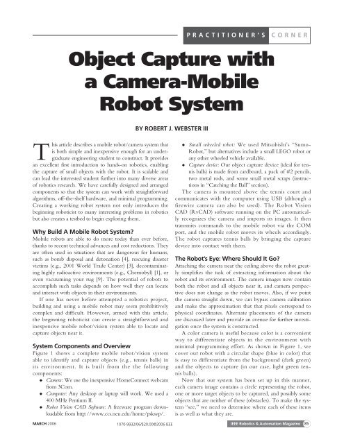
PRACTITIONER’S CORNER<br />
<strong>Object</strong> <strong>Capture</strong> <strong>with</strong><br />
a <strong>Camera</strong>-<strong>Mobile</strong><br />
<strong>Robot</strong> <strong>System</strong><br />
BY ROBERT J. WEBSTER III<br />
This article describes a mobile robot/camera system that<br />
is both simple and inexpensive enough for an undergraduate<br />
engineering student to construct. It provides<br />
an excellent first introduction to hands-on robotics, enabling<br />
the capture of small objects <strong>with</strong> the robot. It is scalable and<br />
can lead the interested student further into many diverse areas<br />
of robotics research. We have carefully designed and arranged<br />
components so that the system can work <strong>with</strong> straightforward<br />
algorithms, off-the-shelf hardware, and minimal programming.<br />
Creating a working robot system not only introduces the<br />
beginning roboticist to many interesting problems in robotics<br />
but also creates a testbed to begin exploring them.<br />
Why Build A <strong>Mobile</strong> <strong>Robot</strong> <strong>System</strong>?<br />
<strong>Mobile</strong> robots are able to do more today than ever before,<br />
thanks to recent technical advances and cost reductions. They<br />
are often used in situations that are dangerous for humans,<br />
such as bomb disposal and detonation [4], rescuing disaster<br />
victims (e.g., 2001 World Trade Center) [3], decontaminating<br />
highly radioactive environments (e.g., Chernobyl) [1], or<br />
even vacuuming your rug [9]. The potential of robots to<br />
accomplish such tasks depends on how well they can locate<br />
and interact <strong>with</strong> objects in their environments.<br />
If one has never before attempted a robotics project,<br />
building and using a mobile robot may seem prohibitively<br />
complex and difficult. However, armed <strong>with</strong> this article,<br />
the beginning roboticist can create a straightforward and<br />
inexpensive mobile robot/vision system able to locate and<br />
capture objects near it.<br />
<strong>System</strong> Components and Overview<br />
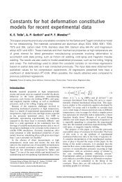
Figure 1 shows a complete mobile robot/vision system<br />
able to identify and capture objects (e.g., tennis balls) in<br />
its environment. It is built from the the following<br />
components:<br />
◆ <strong>Camera</strong>: We use the inexpensive HomeConnect webcam<br />
from 3Com.<br />
◆ Computer: Any desktop or laptop will work. We used a<br />
400 MHz Pentium II.<br />
◆ <strong>Robot</strong> Vision CAD Software: A freeware program downloadable<br />
from http://www.ccs.neu.edu/home/psksvp/.<br />
◆<br />
◆<br />
Small wheeled robot: We used Mitsubishi’s “Sumo-<br />
<strong>Robot</strong>,” but alternatives include a small LEGO robot or<br />
any other wheeled vehicle available.<br />
<strong>Capture</strong> device: Our object capture device (ideal for tennis<br />
balls) is made from cardboard, a pack of #2 pencils,<br />
two metal rods, and some small metal scraps (instructions<br />
in “Catching the Ball” section).<br />
The camera is mounted above the tennis court and<br />
communicates <strong>with</strong> the computer using USB (although a<br />
firewire camera can also be used). The <strong>Robot</strong> Vision<br />
CAD (RvCAD) software running on the PC automatically<br />
recognizes the camera and imports its images. It then<br />
transmits commands to the mobile robot via the COM<br />
port, and the mobile robot moves its wheels accordingly.<br />
The robot captures tennis balls by bringing the capture<br />
device into contact <strong>with</strong> them.<br />
The <strong>Robot</strong>’s Eye: Where Should It Go?<br />
Attaching the camera near the ceiling above the robot greatly<br />
simplifies the task of extracting information about the<br />
robot and its environment. The camera images now contain<br />
both the robot and all objects near it, and camera perspective<br />
does not change as the robot moves. Also, if we point<br />
the camera straight down, we can bypass camera calibration<br />
and make the approximation that that pixels correspond to<br />
physical coordinates. Alternate placements of the camera<br />
are discussed later and provide an avenue for further investigation<br />
once the system is constructed.<br />
A color camera is useful because color is a convenient<br />
way to differentiate objects in the environment <strong>with</strong><br />
minimal programming effort. As shown in Figure 1, we<br />
cover our robot <strong>with</strong> a circular shape (blue in color) that<br />
is easy to differentiate from the background (dark green)<br />
and the objects to capture (in our case, light green tennis<br />
balls).<br />
Now that our system has been set up in this manner,<br />
each camera image contains a circle representing the robot,<br />
one or more target objects to be captured, and possibly some<br />
objects that are neither of these (obstacles). To make the system<br />
“see,” we need to determine where each of these items<br />
is as well as what they are.<br />
MARCH 2006 <strong>IEEE</strong> <strong>Robot</strong>ics & Automation Magazine 85<br />
1070-9932/06/$20.00©2006 <strong>IEEE</strong>
Making the <strong>Robot</strong> See<br />
Machine vision and image processing are very broad areas of<br />
research, and there is an ever-growing number of creative and<br />
useful methods for retrieving information from images. Many<br />
of these are quite complex, but what we desire here is a very<br />
simple way to make the mobile robot see its environment. Our<br />
mobile robot needs to know 1) where it is located, 2) what<br />
direction it is facing, 3) where the tennis ball target object(s) is,<br />
and 4) the location of any obstacles present.<br />
The RvCAD software will automatically import the video<br />
stream from the Webcam, and it provides a simple graphical<br />
interface where one can “wire” together blocks that perform<br />
different image processing functions. We first use a color<br />
threshold (a function built into RvCAD) to decide which pixels<br />
contain robot, tennis ball, background, or something else (an<br />
RS232 from<br />
Com Port<br />
USB or Firewire<br />
Figure 1. The complete mobile robot/camera system consists<br />
of an overhead Webcam, a computer, and a mobile robot<br />
vehicle equipped <strong>with</strong> a device to capture tennis balls. The<br />
overhead camera simplifies the system; pixels approximately<br />
correspond to physical coordinates.<br />
(a)<br />
Overhead<br />
<strong>Camera</strong><br />
Ball<br />
Trap<br />
(b)<br />
Figure 2. Image (a) is obtained directly from the camera.<br />
Image (b) has been thresholded to classify each pixel as<br />
belonging to the robot (purple), tennis ball (red), and obstacle<br />
(yellow) for visualization. Note that the obstacle is nearly the<br />
same color as the tennis balls, and a size check helps determine<br />
which is which. The rectangular bounding boxes in the<br />
image on the right show patches of similarly colored pixels (or<br />
“blobs”) that have been identified.<br />
obstacle). We slightly modify the color threshold function by<br />
specifying ranges for each object in terms of the red, green, and<br />
blue (RGB) content of its pixels (these RGB levels are numbers<br />
ranging from 0–255). Note that the main purpose of this<br />
thresholding step is so that the person using RvCAD can easily<br />
see the classification given to each pixel. This helps the user<br />
tune the RGB color ranges to the appropriate values for the<br />
given background and lighting conditions. One obvious choice<br />
is a red background, a green tennis ball, and a blue robot, but<br />
the specific colors are not important. Any given color can be<br />
described by a range in each component of RGB (a range<br />
instead of one specific value is needed to account for noise in<br />
the camera image). Figure 2 shows an example original and filtered<br />
image using a dark green background. Once the appropriate<br />
range is determined, this color filter block may be<br />
omitted if desired, and the RGB ranges programmed directly<br />
into the findblobs function (described next), or it may be<br />
retained and its output wired into the input of findblobs.<br />
The findblobs function is the next (and last) block we use<br />
in the image processing pipeline we construct in RvCAD. It<br />
locates various areas or “blobs” of similarly colored pixels in<br />
the image. The source code of this block is provided <strong>with</strong><br />
RvCAD. Perhaps the simplest way to figure out what is in<br />
each blob is to test the color of the pixel at the center of the<br />
blob (by making a small modification to the source code to<br />
check which color range it belongs to). The blob that is blue<br />
is the robot, blobs that are light green are tennis balls, and any<br />
blobs <strong>with</strong> other colors are obstacles. Now that we know<br />
what is in the image and where each object is (the center of<br />
each blob is taken to be the object location), the only thing<br />
left to determine is the direction the robot is facing.<br />
The blue marking placed on top of the robot serves two<br />
purposes. First, it makes the center of the blue blob equivalent<br />
to the center of the robot. Second, the small hole cut in<br />
the circle (see Figure 1) provides a way to determine the<br />
direction the robot is facing. This is done by testing pixels<br />
one by one in a circle around the robot center and looking<br />
for pixels that are not blue. While it is possible to use other<br />
markings on top of the robot, other shapes may necessitate<br />
more programming to ascertain not only the location of the<br />
robot’s center but also the direction it faces.<br />
The vision system has now accomplished all objectives. One<br />
small enhancement is to check blob size (since the blobs associated<br />
<strong>with</strong> the robot and the tennis balls are of known size), so<br />
that we can differentiate even blue or green obstacles from the<br />
robot and tennis balls (as in Figure 2). Now that the robot can<br />
“see” its environment and understand all it needs to know, we<br />
are ready to command the robot to move.<br />
Telling the <strong>Robot</strong> Where to Go<br />
A simple way to move the robot to capture a tennis ball is to 1)<br />
turn to face the ball, 2) roll forward for a short time,<br />
and 3) begin again at Step 1. This cycle repeats until the ball is captured<br />
in the ball trap (and thus disappears from the camera view).<br />
86<br />
<strong>IEEE</strong> <strong>Robot</strong>ics & Automation Magazine MARCH 2006
How far and in which direction the robot should turn to<br />
face the ball can be determined by taking the cross product of<br />
two vectors based at the center of the robot. Vector A points<br />
toward the front of the robot, and vector B points toward the<br />
tennis ball. Solving the cross product formula for angle<br />
(θ = sin −1 (|A × B|/|A||B|)) yields the angle the robot should<br />
turn. However, some ambiguity remains because the absolute<br />
values in the above formula mean θ will always be in the first<br />
or fourth quadrants, even if the actual angle the robot should<br />
turn is greater than 90 ◦ in either direction. The correct angle<br />
can be found by taking the dot product between the A and B.<br />
If the sign of the dot product is positive, the robot should turn<br />
θ degrees. If it is negative, then the robot should turn<br />
(180 − θ) degrees.<br />
These calculations can be performed either on the PC or<br />
on the mobile robot’s microcontroller. We chose the latter<br />
because the Sumo-<strong>Robot</strong> has sufficient onboard processing<br />
power. Whichever strategy is selected, information can be<br />
transmitted to the mobile robot by making a minor modification<br />
to the code in “findblobs” allowing it to write to the<br />
COM port. If one is using an alternative to the Sumo-<br />
<strong>Robot</strong>, it may also be useful to consider using the computer’s<br />
parallel port to transmit data.<br />
The mobile robot receives information from the PC and<br />
turns its wheels (one forward and one backward) so that it pivots<br />
about its center until it faces the tennis ball. As mentioned<br />
previously, it then drives forward a short distance before updating<br />
its path. This closed-loop method of driving the robot to<br />
the ball is robust in that it works even in the presence of robot<br />
wheel slippage, tennis ball motion, or multiple tennis balls (provided<br />
the location of the ball closest to the robot is the one<br />
selected as the target).<br />
Catching the Ball<br />
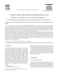
Figure 3 shows a simple, reliable, and inexpensive device for<br />
capturing tennis balls, consisting of a one-way gate. The gate<br />
allows tennis balls in but prevents them from escaping. To<br />
make this ball trap, we bent a thin metal strip into a half-circle<br />
and placed the two thin rods through holes drilled in it.<br />
The ends of the rods are threaded and held in place <strong>with</strong><br />
nuts on the outside of the strip. The pencils serve as the gate<br />
for the trap. Drilling holes through them, they can be suspended<br />
from the lower metal rod in front. The other rod,<br />
placed slightly behind and above the first, serves as a stop to<br />
prevent the pencils from swinging outward. This creates a<br />
one-way gate that allows tennis balls in but not out,<br />
enabling the robot to transport them as desired. The tennis<br />
balls can be released by driving the robot up a ramp so that<br />
the ball trap extends over the edge. The tennis balls will<br />
then fall into a collection basket as shown in Figure 3.<br />
There is an ever-growing number<br />
of creative and useful methods<br />
for retrieving information<br />
from images.<br />
What Else Can You Do <strong>with</strong> It?<br />
The completed mobile robot/vision system project described<br />
here can serve as a launching point for a wide variety of further<br />
explorations of robotics research topics. Some of the the<br />
possible avenues of study have been hinted at previously. For<br />
example, one can consider alternate camera placement<br />
options. Some mobile robotics applications require the camera<br />
to be placed at an angle rather than directly overhead. This<br />
requires the vision and image processing algorithms to deal<br />
<strong>with</strong> perspective as well as camera calibration. There are many<br />
sophisticated algorithms for camera calibration and distortion<br />
correction (including many useful functions in the MATLAB<br />
camera calibration toolbox [2]) that can be investigated by the<br />
interested student.<br />
Other mobile robotics applications call for a camera onboard<br />
the mobile vehicle. This placement causes the camera view to<br />
depend on the robot’s position and orientation. To catch a tennis<br />
ball <strong>with</strong> an onboard camera, one can turn the robot’s<br />
wheels to maintain the tennis ball as closely as possible to the<br />
center of the image. Then, as long as the tennis ball image is<br />
always growing in size, the robot will eventually catch it. This<br />
is an example of visual servoing, and a tutorial on this topic can<br />
be found in [5]. There are many further research issues to<br />
explore <strong>with</strong> onboard placement, such as mapping the environment<br />
based on camera images and the recognition of objects<br />
whose size and perspective can change.<br />
With any choice of camera placement, one can also<br />
investigate obstacle avoidance and navigation. The vision<br />
system described previously is capable of determining the<br />
location of each obstacle in the environment. There are a<br />
wide variety of possible techniques to use this information to<br />
plan paths from the initial robot position and orientation to<br />
a final goal <strong>with</strong>out contacting obstacles [6].<br />
(a)<br />
Ramp<br />
<strong>Robot</strong><br />
(b)<br />
Ball<br />
Trap<br />
Figure 3. (a) The ball capture device is essentially a one-way<br />
gate made from #2 pencil “teeth.” (b) The robot may drive up<br />
a ramp to release tennis balls.<br />
MARCH 2006 <strong>IEEE</strong> <strong>Robot</strong>ics & Automation Magazine 87
Some mobile robotics<br />
applications require the<br />
camera to be placed at an angle.<br />
Another broad research area that can be investigated <strong>with</strong><br />
this system is nonholonomic robotics. If, instead of simply<br />
catching the tennis ball, we want the robot to approach it<br />
from a specific direction, a simple straight line path will no<br />
longer be sufficient. The robot cannot slide sideways around<br />
the ball as it approaches because its wheels impose a nonholonomic<br />
constraint that prevents sideways motion. However, it<br />
is intuitively clear that the robot can perform additional<br />
maneuvers (such as those needed when parallel parking an<br />
automobile) to capture the ball from a specific desired direction.<br />
A thorough treatment of nonholonomy can be found in<br />
[8], and an example directly applicable to the Sumo-<strong>Robot</strong><br />
can be found in [7, Ch. 2]. The unicycle example presented<br />
there is directly analogous to the two-wheeled Sumo-<strong>Robot</strong>.<br />
When operated as described here (so that it moves either in a<br />
straight line or pivots about its center), the Sumo-<strong>Robot</strong> has<br />
the same kinematic constraints as a unicycle.<br />
The issues mentioned above are only a sampling of the<br />
many possible avenues of future research for the interested student.<br />
The challenges and interesting features of such endeavors<br />
have the potential to inspire a student toward continued exploration<br />
in robotics.<br />
Conclusion<br />
The system described in here, known as the “Electronic Ball<br />
Boy,” was developed at the University of Newcastle, Australia.<br />
Videos and additional information can be found in [10] and<br />
[11]. The system was constructed by two undergraduates <strong>with</strong><br />
minimal experience in robotics and no prior computer vision<br />
training. The amount of time required was one semester, as a<br />
senior design project. As an introduction to robotics research,<br />
this project provides exposure to the fields of mobile robotics,<br />
image processing, hardware development, and system integration.<br />
After the initial system is functional, it serves as a testbed<br />
for further investigation and can be taken as far as the student<br />
desires. Constructing this system can be an excellent first introduction<br />
to hands-on robotics research.<br />
Acknowledgments<br />
This work could not have accomplished <strong>with</strong>out Alan<br />
Brannon, who was involved in all phases of the Electronic Ball<br />
Boy project. Rick Middleton and Ian Walker both contributed<br />
ideas, and both Clemson University and the University of Newcastle<br />
in Australia provided financial support for the project.<br />
Keywords<br />
<strong>Mobile</strong> robotics, educational robotics, visual servoing.<br />
References<br />
[1] J. Abouaf, “Trial by fire: Teleoperated robot targets Chernobyl,” <strong>IEEE</strong><br />
Comput Graph. Appl., vol. 18, no. 4, pp. 10–14, 1998.<br />
[2] J.-Y. Bouguet, “<strong>Camera</strong> calibration toolbox for Matlab,” [Online]. Available:<br />
http://www.vision. caltech.edu/bouguetj/calib_doc/index.html<br />
[3] J. Casper and R.R. Murphy, “Human-robot interactions during the robotassisted<br />
urban search and rescue response at the world trade center,” <strong>IEEE</strong><br />
Trans. Syst., Man, Cybern., vol. 33, no. 3, pp. 367–385, 2003.<br />
[4] B.G. DeRoos, J.D. Price, and J.J. Reidy, “Law enforcement robot technology<br />
assessment,” Proc. SPIE, vol. 4232, 2001.<br />
[5] S. Hutchinson, G.D. Hager, and P.I. Corke, “A tutorial on visual servo<br />
control,” <strong>IEEE</strong> Trans. <strong>Robot</strong>. Automat., vol. 12, no. 5, pp. 651–670, 1996.<br />
[6] S.M. LaValle, Planning Algorithms. Cambridge Univ. Press, to be published.<br />
[7] M.T. Mason, Mechanics of <strong>Robot</strong>ic Manipulation. Cambridge, MA: MIT<br />
Press, 2001.<br />
[8] R.M. Murray, Z. Li, and S.S. Sastry, A Mathematical Introduction to <strong>Robot</strong>ic<br />
Manipulation. Ann Arbor MI: CRC Press, 1994.<br />
[9] G. Musser, “<strong>Robot</strong>s that suck. Have they finally come out <strong>with</strong> a robot for<br />
the rest of us?” Sci. Amer., vol. 288, no. 2, pp. 84–86, 2003.<br />
[10] R.J. Webster III and A.S. Brannon,” The electronic ballboy Mark III“<br />
[Online]. Available: http://murray.newcastle.edu.au/users/students/<br />
2001/c2100098/ebb.html<br />
[11] R.J. Webster, III and A.S. Brannon, “The electronic ball boy: A reactive<br />
visually guided mobile robot for the tennis court,” in Proc. <strong>IEEE</strong> Int. Conf.<br />
<strong>Robot</strong>. Automat. (ICRA) 2002, pp. 2054–2059.<br />
Robert J. Webster III is pursuing his Ph.D. in mechanical<br />
engineering at the Johns Hopkins University, where he<br />
received his M.S. in 2004. He received his B.S. in electrical<br />
engineering from Clemson University in 2002. He has<br />
held research positions in mobile and bioinspired robotics<br />
at the University of Newcastle in Australia and at the<br />
Savanna River Site, respectively. His current dissertation<br />
research focuses on the design of miniature flexible medical<br />
robots. This includes steerable needles and active cannulas<br />
to reduce trauma and improve the accuracy of surgery.<br />
Address for Correspondence: Robert Webster, Department of<br />
Mechanical Engineering, The Johns Hopkins University,<br />
223 Latrobe Hall, 3400 North Charles Street, Baltimore,<br />
MD 21218-2681 USA. Phone: +1 410 516 4184. Fax: +1<br />
410 516 7254. E-mail: robert.webster@jhu.edu<br />
88<br />
<strong>IEEE</strong> <strong>Robot</strong>ics & Automation Magazine MARCH 2006