SXVR-H9 handbook.pdf - Starlight Xpress
SXVR-H9 handbook.pdf - Starlight Xpress
SXVR-H9 handbook.pdf - Starlight Xpress

You also want an ePaper? Increase the reach of your titles
YUMPU automatically turns print PDFs into web optimized ePapers that Google loves.
Handbook for the <strong>SXVR</strong>-<strong>H9</strong> Issue 1 June 2009<br />
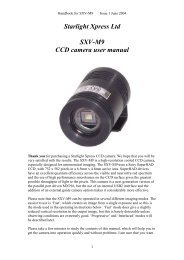
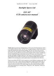
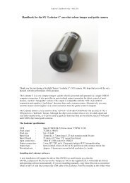
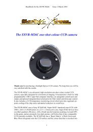
The <strong>SXVR</strong>-<strong>H9</strong> USB2 CCD camera<br />
Thank you for purchasing a <strong>Starlight</strong> <strong>Xpress</strong> CCD camera. We hope that you will be<br />
very satisfied with the results.<br />
The <strong>SXVR</strong>-<strong>H9</strong> is an advanced, high-resolution cooled CCD camera, especially<br />
designed for astronomical imaging. It is a third generation version of the very popular<br />
SXV-<strong>H9</strong> and incorporates many substantial improvements and extra features. These<br />
include a built-in, fully programmable, USB 2 super-fast computer interface, an<br />
autoguider control port and output and optional integrated dual serial ports for filter<br />
wheel and telescope control. It also includes a CCD temperature monitoring circuit<br />
which provides regulated set-point cooling of the chip and a substantial reduction in<br />
overall size.<br />
The <strong>SXVR</strong>-<strong>H9</strong> uses a Sony ICX285AL ‘ExView’ progressive scan CCD, with 1392 x<br />
1040 x 6.45uM pixels in an 8.98 x 6.71mm active area. ExView devices have<br />
1
Handbook for the <strong>SXVR</strong>-<strong>H9</strong> Issue 1 June 2009<br />
excellent quantum efficiency, with a broad spectral response peaking at around 65%<br />
in the green, and an extremely low dark current, well below that of any comparable<br />
CCD currently available. While this device has an excellent blue light sensitivity, it<br />
also has a strong infra-red response, which makes it ideal for all aspects of both<br />
planetary and deep-sky imaging, especially with an H-alpha filter.<br />
The full-frame download time is approximately 0.6 seconds and a binned 4x4<br />
download takes only 0.1 seconds, so finding and centring are very quick and easy in<br />
this mode.<br />
Please take a few minutes to study the contents of this manual, which will help you to<br />
get the camera into operation quickly and without problems. I am sure that you want<br />
to see some results as soon as possible, so please move on to the ‘Quick Start’ section,<br />
which follows. A more detailed description of imaging techniques will be found in a<br />
later part of this manual.<br />
‘Quick Starting’ your <strong>SXVR</strong>-<strong>H9</strong> system<br />
In the shipping container you will find the following items:<br />
1) The <strong>SXVR</strong>-<strong>H9</strong> camera head.<br />
2) A universal AC power supply module.<br />
3) A USB camera cable.<br />
4) An adaptor for 1.25” drawtubes, with a 1.25” filter thread.<br />
5) An adaptor for 2” drawtubes and M42 Pentax thread lenses.<br />
6) A guider output to guider port lead.<br />
7) A disk with the <strong>SXVR</strong>-<strong>H9</strong> control software and this manual.<br />
Optional extra items include:<br />
1) A serial port adaptor and cable.<br />
2) An add-on guide camera head.<br />
You will also need a PC computer with Windows 98, Windows Me, Windows 2000<br />
or Windows XP/Vista installed (NOT Windows 95 or NT4). This machine must have<br />
at least one USB 2.0 port available and at least 256 Mbytes of memory. If you intend<br />
to view the finished images on its screen, then you will also need a graphics card<br />
capable of displaying an image with a minimum of 1024 x 768 pixels and 65,000<br />
colours. A medium specification Pentium with between 1GHz and 4GHz processor<br />
speed is ideal. Please note that USB 2.0 operates at a very high speed and cannot<br />
operate over very long cables. Five metres of good quality cable is the maximum<br />
normally possible without boosters or extra powered hubs.<br />
2
Handbook for the <strong>SXVR</strong>-<strong>H9</strong> Issue 1 June 2009<br />
Installing the USB system:<br />
First, find a free USB socket on your PC and plug in the USB cable (do not connect<br />
the camera at this time). If you do not have a USB2 capable computer, it is normally<br />
possible to install a USB 2 card into an expansion slot.<br />
The next operation is to run the software installer from the CD ROM provided. Insert<br />
the CD into the computer and wait for Windows Explorer to open with the list of<br />
folders on the ROM. Now find the <strong>SXVR</strong>-<strong>H9</strong> folder and run the SETUP.EXE file that<br />
it contains – this will initiate the self-install software which will guide you through the<br />
process of installing the SX camera software (SXV_hmf_usb.exe) onto your<br />
computer.<br />
Now connect the USB cable to the socket on the camera rear panel.<br />
Windows will report ‘Found new hardware’ and will ask for the location of the<br />
drivers. Point the installer at your CD ROM and the driver installation should proceed<br />
smoothly. (Ignore any warnings about the driver having not been tested by Microsoft).<br />
3
Handbook for the <strong>SXVR</strong>-<strong>H9</strong> Issue 1 June 2009<br />
At the end of this process, the USB interface will be installed as a ‘BlockIOClass<br />
device’ and the camera software will be able to access it. You can confirm that the<br />
installation is complete by checking the status of the USB devices in the Windows<br />
‘Device Manager’ (see above). Start up the Windows ‘Control Panel’ and select<br />
‘System’. Now click on the tab labelled ‘Device Manager’, ‘Hardware’, and all of the<br />
system devices will be displayed in a list (see above). If the installation is successful,<br />
there will be a diamond shaped symbol labelled ‘BlockIOClass’ and clicking on the<br />
‘+’ sign will reveal it to be a ‘<strong>Starlight</strong> <strong>Xpress</strong> USB 2.0 SXV-<strong>H9</strong> BlockIO camera<br />
driver’. If this device shows as faulty, try clicking on it and selecting ‘properties’ and<br />
then ‘update driver’. Following the on screen instructions will allow you to re-select<br />
the correct inf file (SXVIO_<strong>H9</strong>_119.inf) and driver files (SXVIO.sys and<br />
generic.sys), which should fix the problem.<br />
Now connect up the power supply and switch it on. The supply is a very efficient<br />
‘switch mode’ unit, which can operate from either 110v or 220v AC via an<br />
appropriate mains power cable (supplied). You can now start the ‘SXV_hmf_usb’<br />
software by double clicking on the icon when you should see the main menu and<br />
image panel appear. If this is the first time that it has been run, you will receive a<br />
warning about the lack of an ‘ini’ file – just click on ‘OK’ and then open ‘Set program<br />
defaults’ from the ‘File’ menu. In the bottom right hand corner of this box, select<br />
SXV-<strong>H9</strong>. Now click on ‘Save’ and the ini file will be created and the software set for<br />
your camera.<br />
Now click on the camera icon at the top of the screen. If the USB connection is OK, a<br />
message box will inform you of the ‘Handle’ number for the SXVIO interface and<br />
4
Handbook for the <strong>SXVR</strong>-<strong>H9</strong> Issue 1 June 2009<br />
various other version details etc. Click ‘OK’ and the main camera control panel will<br />
now be seen.<br />
As can be seen above, there is a CCD temperature monitoring window at the right<br />
hand side of the panel. At switch-on, this will default to full power cooling with an<br />
end point of -40C and, needless to say, this is rather extreme. I recommend changing<br />
the set point to about -10C for normal use, but you can go much colder if you are<br />
imaging during the winter months. Under indoor conditions, the low airflow will limit<br />
the cooling capability, and you should use a set point of no lower than -5C for stable<br />
cooling. You can determine the optimum settings for your camera and ambient<br />
conditions when you have some experience of using the system, but do not try to<br />
operate at extreme cooling when the air temperature is high.<br />
Recording your first image:<br />
We now have the camera and computer set up to take pictures, but an optical system<br />
is needed to project an image onto the CCD surface. You could use your telescope,<br />
but this introduces additional complications, which are best avoided at this early<br />
stage. There are two simple options, one of which is available to everyone with a<br />
sheet of aluminium baking foil:<br />
1) Attach a standard ‘M42’ SLR camera lens to the <strong>SXVR</strong>-<strong>H9</strong>, using the 26mm<br />
spacer to achieve the correct focal distance.<br />
5
Handbook for the <strong>SXVR</strong>-<strong>H9</strong> Issue 1 June 2009<br />
Or<br />
2) Create a ‘Pin hole’ lens by sticking a sheet of aluminium baking foil over the end<br />
of the adaptor and pricking its centre with a small pin.<br />
If you use a normal lens, then stop it down to the smallest aperture number possible,<br />
(usually F22), as this will minimise focus problems and keep the light level<br />
reasonable for daytime testing. The pin hole needs no such adjustments and will work<br />
immediately, although somewhat fuzzily!<br />
6
Handbook for the <strong>SXVR</strong>-<strong>H9</strong> Issue 1 June 2009<br />
Point the camera + lens or pinhole towards a well-lit and clearly defined object some<br />
distance away. Now enter the ‘File’ menu in the SXV_<strong>H9</strong> software and click on ‘SX<br />
camera interface’. Select an exposure time of 0.1 seconds and press ‘Take Photo’.<br />
After the exposure and download have completed (about 1 second) an image of some<br />
kind will appear on the computer monitor. It will probably be poorly focused and<br />
incorrectly exposed, but any sort of image is better than none! In the case of the<br />
pinhole, all that you can experiment with is the exposure time, but a camera lens can<br />
be adjusted for good focus and so you might want to try this to judge the high image<br />
quality that it is possible to achieve.<br />
Various other exposure options are available, as can be seen in the picture above. For<br />
example, you can ‘Bin’ the download 2x2, or more, to achieve greater sensitivity and<br />
faster download, or enable ‘Continuous mode’ to see a steady stream of images.<br />
‘Focus mode’ downloads a 128 x 128 segment of the image at high speed. The initial<br />
position of the segment is central to the frame, but can be moved by selecting ‘Focus<br />
frame centre’ in the ‘File’ menu and clicking the desired point with the mouse. The<br />
focus window has an adjustable ‘contrast stretch’, controlled by the 12-16 bit slider.<br />
The image will be ‘normal’ if 16 bits is selected, while setting lower values will<br />
increase the image brightness in inverse proportion.<br />
If you cannot record any kind of image, please check the following points:<br />
1) Ensure that the power indicator lamp is on and that the cables are properly home<br />
in their sockets.<br />
2) If the screen is completely white, the camera may be greatly overexposed. Try a<br />
shorter exposure time, or stop down your lens. See if covering the lens causes the<br />
image to darken.<br />
3) If the USB did not initialise properly, the camera start-up screen will tell you that<br />
the connection is defective. Try switching off the power supply and unplugging the<br />
USB cable. Now turn the power supply on and plug in the USB cable. This will reload<br />
the USB software and may fix the problem after restarting the SXV_hmf_usb<br />
program. Otherwise, check the device driver status, as previously described, and<br />
re-install any drivers which appear to be defective.<br />
4) If you cannot find any way of making the camera work, please try using it with<br />
another computer. This will confirm that the camera is OK, or faulty, and you can<br />
then decide how to proceed. Our guarantee ensures that any electrical faults are<br />
corrected quickly and at no cost to the customer.<br />
Image enhancements:<br />
Your first image may be satisfactory, but it is unlikely to be as clear and sharp as it<br />
could be. Improved focusing and exposure selection may correct these shortcomings,<br />
and you may like to try them before applying any image enhancement with the<br />
software. However, there will come a point when you say, “That’s the best that I can<br />
get” and you will want to experiment with the effects of image processing. In the case<br />
of daylight images, the processing options are many, but there are few that will<br />
improve the picture in a useful way. The most useful of these are the ‘Normal<br />
Contrast Stretch’ and the ‘High Pass Low Power’ filter. The high pass filter gives a<br />
7
Handbook for the <strong>SXVR</strong>-<strong>H9</strong> Issue 1 June 2009<br />
moderate improvement in the image sharpness, and this can be very effective on<br />
daylight images.<br />
Too much high pass filtering results in dark borders around well-defined features and<br />
will increase the noise in an image to unacceptable levels, but the Low Power filter is<br />
close to optimum and gives a nicely sharpened picture.<br />
The ‘Contrast’ routines are used to brighten (or dull) the image highlights and<br />
shadows. A ‘Normal’ stretch is a simple linear operation, where two pointers (the<br />
‘black’ and ‘white’ limits) can be set at either side of the image histogram and used to<br />
define new start and end points. The image data is then mathematically modified so<br />
that any pixels that are to the left of the ‘black’ pointer are set to black and any pixels<br />
to the right of the ‘white’ pointer are set to white. The pixels with values between the<br />
pointers are modified to fit the new brightness distribution. Try experimenting with<br />
the pointer positions until the image has a pleasing brightness and ‘crispness’.<br />
At this point, you will have a working knowledge of how to take and process an<br />
<strong>SXVR</strong>-<strong>H9</strong> image. It is time to move on to astronomical imaging, which has its own,<br />
unique, set of problems!<br />
*********************************************************************<br />
Astronomical Imaging with the <strong>SXVR</strong>-<strong>H9</strong><br />
1) Getting the image onto the CCD:<br />
It is fairly easy to find the correct focus setting for the camera when using a standard<br />
SLR lens, but quite a different matter when the <strong>SXVR</strong>-<strong>H9</strong> is attached to a telescope!<br />
The problem is that most telescopes have a large range of focus adjustment and the<br />
CCD needs to be quite close to the correct position before you can discern details well<br />
enough to optimise the focus setting. An additional complication is the need to add<br />
various accessories between the camera and telescope in order that the image scale is<br />
suitable for the subject being imaged and (sometimes) to include a ‘flip mirror’ finder<br />
unit for visual object location.<br />
A simple, but invaluable device, is the ‘par-focal eyepiece’. This is an eyepiece in<br />
which the field stop is located at the same distance from the barrel end, as the CCD is<br />
from the camera barrel end.<br />
8
Handbook for the <strong>SXVR</strong>-<strong>H9</strong> Issue 1 June 2009<br />
When the par-focal eyepiece is fitted into the telescope drawtube, you can adjust the<br />
focus until the view is sharply defined and the object of interest is close to the field<br />
centre. On removing the eyepiece and fitting the CCD camera, the CCD will be very<br />
close to the focal plane of the telescope and should record the stars etc. well enough<br />
for the focus to be trimmed to its optimum setting<br />
Several astronomical stores sell adjustable par-focal eyepieces, but you can also make<br />
your own with a minimum of materials and an unwanted Kellner or Plossl ocular.<br />
Just measure a distance of 22mm from the field stop of the eyepiece (equivalent to the<br />
CCD to adaptor flange distance of the camera) and make an extension tube to set the<br />
field stop at this distance from the drawtube end. Cut-down 35mm film cassette<br />
containers are a convenient diameter for making the spacer tube and may be split to<br />
adjust their diameter to fit the drawtube.<br />
It is necessary to set up a good optical match between your camera and the telescope.<br />
Most SCTs have a focal ratio of around F10, which is too high for most deep sky<br />
objects and too low for the planets! This problem is quite easy to overcome, if you<br />
have access to a focal reducer (for deep sky) and a Barlow lens for planetary work.<br />
The Meade F6.3 focal reducer is very useful for CCD imaging and I can recommend<br />
it from personal experience. It does not require a yellow filter for aberration<br />
correction, unlike some other designs, so it can also be used for tri-colour imaging. If<br />
you use a focal reducer, using it at maximum reduction may cause the relatively large<br />
chip of the <strong>SXVR</strong>-<strong>H9</strong> to suffer from considerable ‘vignetting’ (dimming towards the<br />
corners) and this will be difficult to remove from your images. Experiment with the<br />
distance between the reducer and the camera to optimise the results. The longer the<br />
extension tube used, the greater the focal reduction will be. As a guide, most CCD<br />
astronomers try to maintain an image scale of about 2 arc seconds per pixel for deep<br />
sky images. This matches the telescope resolution to the CCD resolution and avoids<br />
‘undersampling’ the image, which can result in square stars and other unwanted<br />
effects. To calculate the focal length required for this condition to exist, you can use<br />
the following simple equation:<br />
F = Pixel size * 205920 / Resolution (in arc seconds)<br />
In the case of the <strong>SXVR</strong>-<strong>H9</strong> and a 2 arc seconds per pixel resolution, we get<br />
F = 0.00645 * 205920 / 2<br />
= 664mm<br />
For a 200mm SCT, this is an F ratio of 664 / 200 = F3.32, which is rather less than<br />
can be achieved with the Meade converter and appropriate extension tube. However,<br />
moderate deviations from this focal length will not have a drastic effect and so any F<br />
ratio from about F4.5 to F6.3 will give good results.<br />
The same equation can be used to calculate the amplification required for good<br />
planetary images. However, in this case, the shorter exposures allow us to assume a<br />
much better telescope resolution and 0.25 arc seconds per pixel is a good value to use.<br />
The calculation now gives the following result:<br />
F = 0.00645 * 205920 / 0.25 = 5354mm<br />
9
Handbook for the <strong>SXVR</strong>-<strong>H9</strong> Issue 1 June 2009<br />
This is approximately F27 when used with a 200mm SCT and so we will need a 2.8x<br />
Barlow lens and the common 3x version will be good enough for all practical<br />
purposes. Barlow lenses are less critical than focal reducers and most types can be<br />
used with good results. However, if you are buying one especially for CCD imaging, I<br />
recommend getting a 3x or 5x amplifier, or the planets will still be rather small in<br />
your images.<br />
Achieving a good focus:<br />
Your starting point will depend on the focus aids, if any, which you are using. With<br />
the par-focal eyepiece, you should slip the eyepiece into the drawtube and focus<br />
visually on a moderately bright star (about 3 rd magnitude). Now withdraw the<br />
eyepiece and carefully insert the camera nosepiece, until it is bottomed against the<br />
drawtube end, and then lock it in place.<br />
SXV_hmf_usb.exe has a focus routine that will repeatedly download and display a<br />
128 x 128 pixel segment of the image at relatively high speed. This focus window<br />
may be positioned anywhere in the camera field and can be displayed with an<br />
adjustable degree of automatic contrast stretching (for focusing on faint stars). To use<br />
this mode, start up the software and select the SXV camera interface (File menu). Set<br />
the camera mode to Binned 1x1 and select an exposure time of 1 second. Press ‘Take<br />
Picture’ and wait for the image to download. There is a good chance that your<br />
selected star will appear somewhere within the image frame and it should be close to<br />
a sharp focus. If the focus is still poor, then it may appear as a pale disk of light, often<br />
with a dark centre (the secondary mirror shadow in an SCT, or Newtonian). Now<br />
select the ‘File’ menu again and click on ‘Focus frame centre’; you can now use the<br />
mouse pointer to click on the star image and the new focus frame co-ordinates will be<br />
displayed. Now return to the camera interface window and click on ‘Start’ in the<br />
Focus frame. The computer will now display a continuous series of 128 x 128 pixel<br />
images in the focus window and you should see your selected star appear somewhere<br />
close to the centre. A ‘peak value’ (the value of the brightest pixel) will also be shown<br />
in the adjacent text box and this can be used as an indication of the focus accuracy.<br />
Although the peak value is sensitive to vibration and seeing, it tends towards a<br />
maximum as the focus is optimised. Carefully adjust the focus control on your<br />
telescope until the image is as sharp as possible and the peak value reaches a<br />
maximum. Wait for any vibration to die down before accepting the reading as reliable<br />
and watch out for bursts of bad seeing, which reduce the apparent focus quality. Quite<br />
often, the peak value will increase to the point where it is ‘off scale’ at 4095 and in<br />
this case you must halt the focus sequence and select a shorter exposure if you wish to<br />
use the peak value as an indicator. Once you are happy with the focus quality<br />
achieved, you might like to trim the settings of your par-focal or flip mirror eyepiece<br />
to match the current camera position.<br />
Although you can reach a good focus by the above method, many observers prefer to<br />
use additional aids, such as Hartmann or Bahnitov masks (an objective cover with<br />
several spaced holes) or diffraction bars (narrow parallel rods across the telescope<br />
aperture). These make the point of precise focus easier to determine by creating<br />
‘double images’ or bright diffraction spikes around stars, which merge at the setting<br />
of exact focus. The 12-16 bit slider control allows you to adjust the contrast of the<br />
focus frame for best visibility of the star image. It defaults to maximum stretch (12<br />
10
Handbook for the <strong>SXVR</strong>-<strong>H9</strong> Issue 1 June 2009<br />
bits), which is generally ideal for stars, but a lower stretch value is better for focusing<br />
on planets.<br />
Taking your first astronomical image:<br />
I will assume that you are now set up with a focused camera attached to a telescope<br />
with an operating sidereal drive. If so, you are now in a position to take a moderately<br />
long exposure of some interesting deep-sky astronomical object (I will deal with<br />
planets later). As most drives are not very accurate beyond a minute or two of<br />
exposure time, I suggest that you find a fairly bright object to image, such as M42,<br />
M13, M27 or M57. There are many others to choose from, but these are good<br />
examples.<br />
Use the finder to align on your chosen object and then centre accurately by using the<br />
focus frame and a short exposure of between 1 and 5 seconds. The ’12-16 bit’ slider<br />
in the focus frame allows you to adjust the image contrast if you find that the object is<br />
too faint with a short exposure. Once properly centred and focused, take an exposure<br />
of about 60 seconds, and observe the result. Initially, the image may appear rather<br />
barren and show only a few stars, however, there is a great deal of data hidden from<br />
view. You can get to see a lot of this, without affecting the image data, if you go to<br />
the ‘View’ menu and select ‘Auto Contrast Stretch Image’. The faint image data will<br />
then appear in considerable detail and I think that you will be impressed by the result!<br />
If you are happy with the image, go to the ‘File’ menu and save it in a convenient<br />
directory.<br />
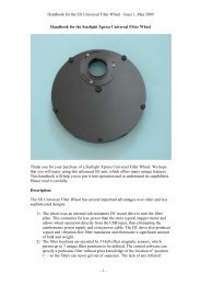
A 60 second exposure of M42 through an H-alpha filter (non-linear stretched)<br />
Most competitive brands of CCD camera require a ‘dark frame’ to be subtracted from<br />
your images to achieve the best results. A dark frame is simply a picture which was<br />
11
Handbook for the <strong>SXVR</strong>-<strong>H9</strong> Issue 1 June 2009<br />
taken with the same exposure as your ‘light frame’, but with the telescope objective<br />
covered, so that no light can enter. It records only the ‘hot pixels’ and thermal<br />
gradients of your CCD, so that these defects are largely removed when the dark frame<br />
is subtracted from the light frame. The <strong>SXVR</strong>-<strong>H9</strong> CCD is quite different from those<br />
used in other brands of camera and generates an extremely low level of dark noise.<br />
Indeed, it is so low that subtracting a dark frame can actually INCREASE the noise in<br />
your images! This is because the statistical noise of the dark frame can exceed the<br />
‘pattern noise’ from warm pixels and hence add to that of the subtracted result. If your<br />
test pictures have an exposure time of less than about 10 minutes (as above), then<br />
don’t bother with a dark frame, just ‘kill’ any hot pixels with your processing<br />
software. In <strong>SXVR</strong>-<strong>H9</strong>, the ‘Median filter’ can do this, but other software (e.g.<br />
Maxim DL) will provide a ‘hot pixel killer’ that can be mapped to specific locations<br />
in the image, or methods such as ‘Sigma combine’ may be used.<br />
In the unlikely event that you feel that dark frame really is necessary, please proceed<br />
as follows:<br />
To take a dark frame, just cover the telescope objective with the lens cap and take<br />
another exposure with the same length as that of the light frame. This image will be a<br />
picture of the dark signal generated during your exposure and it should be saved with<br />
your image for use in processing the picture. If many such darks are recorded and<br />
averaged together, the statistical noise will be reduced, but the gains to be had are<br />
rather small compared with the effort involved.<br />
As variations in ambient temperature will affect the dark signal, it is best to take the<br />
dark frames within a few minutes of capturing your images. For the same reason, it is<br />
not wise to use ‘old’ dark frames if you want the best possible results, however, some<br />
software allows you to scale library dark frames to match the image (e.g. AstroArt)<br />
and this can be useful as a time saver.<br />
‘Bias frames’ are somewhat more useful than dark frames when using the <strong>SXVR</strong>-<strong>H9</strong>.<br />
A bias frame is essentially a zero exposure dark frame and records any minor readout<br />
defects that the CCD may possess, so a ‘bias frame subtraction’ can clean up any<br />
‘warm columns’ or shadings that are created during readout. To record a bias frame,<br />
cover the camera aperture and take a 1000 th of a second exposure. If you take at least<br />
10 such frames and average them together, the resulting ‘master bias’ can be used to<br />
clean up readout defects for many months before CCD ageing changes require another<br />
set to be recorded.<br />
‘Flat fields’ are often recommended for optimising the results from your CCD<br />
camera, but these are generally less important than dark frames, especially if you<br />
make sure that the optical window of the camera is kept dust-free. The purpose of a<br />
flat field is to compensate for uneven illumination and sensitivity of the CCD and it is<br />
better to avoid the need for one by keeping the optics clean and unvignetted. I will<br />
ignore flat fielding for current purposes and describe the process in detail at a later<br />
stage.<br />
12
Handbook for the <strong>SXVR</strong>-<strong>H9</strong> Issue 1 June 2009<br />
Processing a deep-sky image:<br />
The following instructions include the subtraction of a dark frame, but this may be<br />
regarded as optional.<br />
1) Make sure the ‘Auto Contrast Stretch’ is switched off and load your image into<br />
SXV_hmf_usb. Select ‘Merge’ and then ‘Subtract Dark Frame’. Pick the appropriate<br />
dark frame and the software will then remove the dark signal from your image,<br />
leaving it somewhat darker and slightly smoother than before.<br />
13
Handbook for the <strong>SXVR</strong>-<strong>H9</strong> Issue 1 June 2009<br />
3) The resulting image will probably look faint and dull, with a pale background due<br />
to light pollution. It is now time to process the ‘luminance’ (brightness and contrast)<br />
of the image to get the best visual appearance. First, use the ‘Normal’ contrast stretch<br />
to darken the background by setting the ‘Black’ slider just below the main peak of the<br />
histogram. Alternatively, you can use the ‘Remove Background’ option to let the<br />
software decide on the best setting. This will greatly reduce the background<br />
brightness and the image will begin to look rather more attractive, although dark. You<br />
can now try brightening the highlights with another ‘Normal’ stretch, in which you<br />
bring down the ‘White’ slider to just above the main image peak. The best setting for<br />
this is rather more difficult to guess and you may need several attempts before the<br />
result is ideal. Just use the ‘Undo last filter’ function, if necessary, to correct a<br />
mistake.<br />
4) The image will now look quite impressive and I hope that you are pleased with<br />
your first efforts!<br />
In many cases, a ‘Normal’ contrast stretch will give a good result, but may ‘burn out’<br />
the bright regions and leave the faint parts of the image rather lacking in brightness.<br />
To combat this, many imagers will use a combination of ‘Normal’ and ‘Non-linear’<br />
contrast stretches. The best settings are different for different objects, but performing<br />
a non-linear or power law stretch, followed by normalising the background to black<br />
with a normal stretch, is the usual procedure.<br />
Further small refinements are usually possible and you will become expert at judging<br />
the best way to achieve these as your experience increases. As a rough guide, the<br />
‘Filters’ menu can be used to sharpen, soften or noise reduce the image. Strong ‘High<br />
Pass’ filters are usually not a good idea with deep sky images, as the noise will be<br />
strongly increased and dark rings will appear around the stars, but a ‘Median’ filter<br />
can remove odd speckles and a mild ‘Unsharp Mask’ (Radius 3, Power 1) will<br />
sharpen without too much increase in noise.<br />
14
Handbook for the <strong>SXVR</strong>-<strong>H9</strong> Issue 1 June 2009<br />
Other things to try, include summing several images for a better signal to noise ratio.<br />
Summing can be done in the ‘Merge’ menu and involves loading the first processed<br />
image, selecting a reference point (a star) then loading the second image and finding<br />
the same star with the mouse. Once the reference is selected, you can either add<br />
directly, or average the images together. Averaging is generally better, as you are less<br />
likely to saturate the highlights of the picture. The signal-to-noise ratio will improve<br />
at a rate proportional to the square root of the number of summations (summing 4<br />
images will double the signal-to-noise), but different exposures must be used.<br />
Summing an image with itself will not improve the S/N ratio!<br />
Although I have concentrated on the use of a telescope for deep-sky imaging, do not<br />
forget that you have the option of using an ordinary camera lens for impressive widefield<br />
shots! A good quality 200mm F3.5 lens with an infrared blocking filter will yield<br />
very nice images of large objects, such as M31, M42, M45 etc. If you cannot obtain a<br />
large IR blocker for the front of the lens, it is quite acceptable to place a small one<br />
behind the lens, inside the adaptor tube. You can even try using a hydrogen-alpha<br />
filter to bring out nebulae, reduce light pollution and sharpen the star images to pinpoints.<br />
Taking pictures of the planets:<br />
Planetary imaging is in many ways quite different from deep sky imaging. Most deep<br />
sky objects are faint and relatively large, so a short focal length and a long exposure<br />
are needed, while planets are bright and very small, needing long focal lengths and<br />
short exposures. High resolution is critical to achieving good results and I have<br />
already shown how a suitable focal length can be calculated and produced, using a<br />
Barlow lens.<br />
Many camera users comment on the difficulty of finding the correct focus when<br />
taking pictures of Jupiter etc. This is usually due to poor seeing conditions, which are<br />
only too common, but may also be due in part to poor collimation of your telescope.<br />
Please ensure that the optics are properly aligned as shown by star testing, or by using<br />
one of the patent collimation aids that are widely available. It is also better to use a<br />
star for initial focusing, as planetary detail is difficult to judge in bad seeing. Although<br />
the star will also suffer from blurring, the eye can more easily gauge when the most<br />
compact blur has been achieved!<br />
You could begin by imaging lunar craters, or the planets, Jupiter, Saturn or Mars. The<br />
rapid variations of seeing which accompany planetary imaging, will ruin the<br />
definition of about 95% of your images and so I recommend setting the camera to run<br />
in ‘Autosave’ mode. This will automatically take a sequence of images and save them<br />
with sequential file names in your ‘Autosave’ directory. Dozens of images will be<br />
saved, but only one or two will be satisfactory for further processing. The ‘Subframe’<br />
mode of the SXV may be found useful for limiting the wasted area and reducing the<br />
download time of small planetary images.<br />
To start the Autosave process, call up the SXV Camera Interface and select the<br />
‘Continuous Mode’ check box at the top (make sure the rest are unchecked). Now<br />
check the ‘Autosave Image’ checkbox near the bottom of the window. If you now<br />
15
Handbook for the <strong>SXVR</strong>-<strong>H9</strong> Issue 1 June 2009<br />
click on ‘Take Picture’ the automatic sequence will begin and will not stop until you<br />
press a computer key. The images will be saved in FITs format with sequential names<br />
such as ‘Img23, Img24….’ and will be found in the ‘Autosave’ directory (or a subdirectory<br />
of Autosave, set up in the program defaults menu).<br />
The exposure time needed for good planetary images is such that the image histogram<br />
has a peak value at around 200 and does not extend much above 220 (Ignore the<br />
major peak near zero, due to the dark background). If you use too short an exposure<br />
time, the image noise level will be increased, and if too long a time is used you will<br />
saturate the highlights and cause white patches on the image. With the recommended<br />
focal length, Jupiter and Mars will both need an exposure time of between 0.1 and 1<br />
seconds and Saturn will need between 0.5 and 2 seconds.<br />
Processing a planetary image:<br />
Planetary images have one major advantage over deep sky images, when you come to<br />
process them – they are MUCH brighter, with a correspondingly better signal to noise<br />
ratio. This means that aggressive sharpening filters may be used without making the<br />
result look very noisy and so some of the effects of poor seeing can be neutralised.<br />
A raw image<br />
Try applying an ‘Unsharp Mask’ filter with a radius of 5 and a power of 5. This will<br />
greatly increase the visibility of any detail on the planet, but the optimum radius and<br />
power will have to be determined by experiment.<br />
16
Handbook for the <strong>SXVR</strong>-<strong>H9</strong> Issue 1 June 2009<br />
After the application of an ‘Unsharp mask’<br />
In general terms, the larger the image and the worse the seeing, then the wider the<br />
radius for best results. My Jupiter shots are usually about one third the height of the<br />
CCD frame and I find that the ‘radius 5, power 5’ values are good for most average<br />
seeing conditions. If you have exceptionally good conditions, then a reduction to R=3,<br />
P=3 will probably give a more natural look to the image, as too large a radius and<br />
power tends to outline edges with dark or bright borders.<br />
As a finishing touch, the application of a Median filter or a Weighted Mean Low Pass<br />
filter can be useful to smooth out the high frequency noise after a strong Unsharp<br />
Mask.<br />
As with deep-sky images, it is advantageous to sum planetary images together to<br />
improve the signal to noise ratio. In this case, the ‘averaging’ option should always be<br />
used, or the result is likely to exceed the dynamic range of the software and saturate<br />
the highlights. Aligning the images is always something of a problem, as there are<br />
rarely any stars to use when imaging the planets, but Jupiter’s satellites can be useful<br />
reference points. Otherwise, you will have to find a well-defined feature on the planet,<br />
or estimate where the centre of the disk is located. Some more sophisticated software<br />
can automatically align planetary images and you may find these programs (e.g.<br />
‘Registax’) to be very useful.<br />
*********************************************************************<br />
Using the add-on autoguider:<br />
A very useful accessory is the add-on autoguider head, which takes its power and<br />
control signals directly from the <strong>SXVR</strong> camera, via the 18 way socket on its rear<br />
panel. The autoguider is only 1.25” in diameter and has a video style ‘CS’ mount<br />
thread in its nose, so video lenses may be attached. The guider may be used with<br />
17
Handbook for the <strong>SXVR</strong>-<strong>H9</strong> Issue 1 June 2009<br />
either an off-axis prism assembly mounted in front of the <strong>SXVR</strong> camera, or with a<br />
separate guide telescope, rigidly mounted alongside your imaging telescope. I<br />
personally use it with a 70mm aperture, F10, inexpensive refractor as a guide ‘scope,<br />
but a shorter focal length lens will make more guide stars available in any given<br />
region of sky (See the picture below).<br />
To use the autoguider, first orient it so that the connector plug is roughly parallel to<br />
the declination axis of your mount. This is not absolutely essential, as the training<br />
routine will learn the angle of the head and compensate for it, but it is easier to<br />
understand the motion of the guide star if the guider frame is aligned with the RA and<br />
Dec axes. Now connect the head to the camera, using the 18 way connector lead,<br />
including the port divider box, if it is to be used.<br />
The recommended way of connecting the autoguider output to the mount is to use an<br />
RJ11 telephone lead between the socket on the SXV camera and the autoguider input<br />
of your mount. This output is ‘active low’ (i.e. the control relays pull the guider inputs<br />
down to zero volts when applying a guide correction) and matches most of the<br />
autoguider inputs on commercial mounts. If ‘active high’ inputs are needed, or a very<br />
low control voltage drop is essential, then you will need to add a <strong>Starlight</strong> <strong>Xpress</strong><br />
‘relay box’ between the guider output and the input to the mount. Please contact your<br />
local distributor if a relay box is required. Some mounts (Vixen, for example) use a<br />
similar guider input socket, but have re-arranged connections. Details are given on our<br />
web pages at the end of the ‘STAR2000’ section.<br />
18
Handbook for the <strong>SXVR</strong>-<strong>H9</strong> Issue 1 June 2009<br />
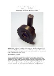
The autoguider installed on a 70mm refractor guide ‘scope in the author’s garden (the<br />
camera shown is the older SXVF version, but the connections are the same).<br />
To use the autoguider, please proceed as follows:<br />
1) Having started the <strong>SXVR</strong>-<strong>H9</strong> software, open the autoguider control panel by<br />
clicking on the autoguider menu button.<br />
19
Handbook for the <strong>SXVR</strong>-<strong>H9</strong> Issue 1 June 2009<br />
The autoguider control panel with a guide star selected<br />
2) Press the ‘Start’ button and a series of 1 second exposure guider images will<br />
begin to appear in the picture frame. If the images look too dim, use the<br />
‘Stretch Image’ slider to increase its contrast and brightness until the noise<br />
begins to be visible.<br />
3) If you haven’t focused the guider lens or ‘scope, move the mount until a bright<br />
star is visible on the guider image and then adjust the focus until it is as sharp<br />
as possible.<br />
4) At this point, you may want to test the guiding control by pressing the manual<br />
‘Move Telescope’ buttons at the bottom left corner of the control panel. You<br />
can watch the position of any stars in the guider image and confirm that they<br />
move in response to the buttons. The movement should be slow if the correct<br />
guiding rate is selected on your mount (typically 2x sidereal). Adjust this, if<br />
necessary.<br />
5) Move the mount until the required object for imaging is properly framed in the<br />
main CCD image (leave the guider menu and use the main camera control<br />
panel, as necessary).<br />
6) Re-open the guider control panel, start imaging and try to locate a clearly<br />
visible guide star. If necessary, make adjustments to the guide telescope or offaxis<br />
guider until one is found.<br />
7) Press ‘Stop’ and then press ‘Select Guide Star’. Use the mouse to left click on<br />
the selected star and a green cross will highlight it and the co-ordinates will<br />
appear in the text boxes above the image window.<br />
8) The various guiding rate defaults, listed on the right-hand side of the control<br />
panel, are unlikely to be perfect for your particular telescope and mount. You<br />
have the option of manually selecting values, or asking the software to attempt<br />
to determine what they should be. This is done by pressing the ‘Train’ button<br />
and waiting for the software to complete a sequence of automatic moves and<br />
calculations. The training will also determine the angle at which the guide<br />
camera is oriented with respect to the RA and Dec axes. If you do not wish to<br />
train the system at this time, the default values of 6 pixels per second will<br />
serve as a starting point.<br />
20
Handbook for the <strong>SXVR</strong>-<strong>H9</strong> Issue 1 June 2009<br />
9) Now press ‘Go to main camera’ and the guider control panel will be replaced<br />
by the camera control panel. Set the required exposure time for the image (say<br />
5 minutes) and press the ‘Autoguide next image’ button. The autoguider<br />
window will reappear and, after a few seconds, you should see error values<br />
appearing in the text windows at the top. The guide star will be fairly close to<br />
the green cross, although not necessarily accurately centred, and you should<br />
see the power/ guide LED on the rear of the camera brighten and change<br />
colour with each correction.<br />
10) If the star begins to drift away from the cross, despite the corrections being<br />
made, the chances are that the N/S and/or E/W directions are set wrongly.<br />
Judge which axis is incorrectly set by observing the direction of the drift and<br />
then stop the exposure by pressing ‘Esc’. Open the guider control panel and<br />
check the appropriate swap box(es). After this operation, you will probably<br />
need to find the guide star again by taking a guider image and reselecting the<br />
star, as before. Now return to the main camera menu and try the ‘Autoguide<br />
next image’ button again.<br />
11) Once guiding is taking place without problems, the main exposure can be<br />
allowed to finish and, if all is well, you should see an image with tiny circular<br />
stars.<br />
If the stars are not circular, you may need to alter the guiding parameters, or<br />
investigate the rigidity and drive performance of your mount. A lot of information<br />
can be deduced by watching the behaviour of the guide star in the guider frame. If<br />
it is continually moving between two locations, either side of the green cross, then<br />
the RA or Dec pixels per second value is set too low. The higher these values are<br />
set, the gentler the guiding becomes. Too low a value will cause an overaggressive<br />
correction to be made and result in oscillation of the star position<br />
between two points.<br />
Another source of guiding errors can be an accurately balanced telescope mount!<br />
Good balance can result in the telescope mount ‘bouncing’ between the gear teeth<br />
as corrections are made. A simple fix is to add a weight of about 0.5kg (1 pound)<br />
on the eastern end of the declination axis, so that there is always some pressure<br />
acting against the gear teeth.<br />
Getting a good result from an autoguider will often entail a lot of detective work<br />
to eliminate the sources of gear error, telescope flexure, mirror shift etc., but the<br />
final result is well worth the effort!<br />
*********************************************************************<br />
Using the built-in serial ports<br />
The <strong>SXVR</strong>-<strong>H9</strong> incorporates two fast serial ports for use with external accessories.<br />
The ports are available on 5 pins of the 18 way connector that is provided for the<br />
autoguider and may be accessed by plugging in a ‘serial port divider box’. The divider<br />
box and cables are available as an accessory and may be chained in series with the<br />
autoguider cable, when the guider is in use, or may be used on its own.<br />
21
Handbook for the <strong>SXVR</strong>-<strong>H9</strong> Issue 1 June 2009<br />
The two serial connections are in the form of standard RS232 PC style plugs and<br />
provide TX, RX and Ground connections at RS232 levels. Access is via commands<br />
sent through the USB connection and, at the time of writing, is limited to any serial<br />
controls that are provided by the SXV software. It is expected that many more<br />
functions will be added as the software is upgraded.<br />
*********************************************************************<br />
Other features of the <strong>SXVR</strong>-<strong>H9</strong> hardware and software<br />
‘Slew & Sum’ imaging:<br />
The <strong>SXVR</strong>-<strong>H9</strong> can be used in an automatic image-stacking mode, called ‘Slew &<br />
Sum’. The camera is set to take several sequential exposures, which are automatically<br />
‘slewed’ into alignment and then summed together by the software. This mode can<br />
help to overcome a poor RA drive by summing images that have exposure times<br />
shorter than the drive error period. The resulting image has more noise than a single<br />
exposure of the same total length, but this method of imaging is still an effective way<br />
of making long exposures without a guider.<br />
To take an S&S image, go to the camera interface window and select an exposure<br />
time for one image of the sequence. Do not use a very short exposure time, as the<br />
read-out noise will become dominant. About 30 seconds is a reasonable minimum.<br />
Now go to the ‘Multiple Exposure Options’ and select a number of exposures to take.<br />
You can also select to average the images, rather than adding them, and there is a<br />
‘Alternative Slew Mode’ available, which uses the correlation of image areas, rather<br />
than a single star. This mode can be better in dense star fields.<br />
Another option is ‘Auto remove dark frame’. This is advisable with S&S images, as<br />
the slewing will mis-register the images with a single dark frame that is applied to the<br />
finished sequence. To use this option, you will need a dark frame, taken with the same<br />
exposure time as a single image from the sequence. This is stored on drive C with the<br />
name ‘dark.def’<br />
Now click on ‘Take Picture’ and the sequence will begin.<br />
Using the ‘Binned’ modes:<br />
Up to this point, I have assumed that the full resolution, imaging mode is being used.<br />
This is fine for most purposes, but it will often provide more resolution than the<br />
optical system, or the seeing, allows. ‘Binned 2x2’ mode sums groups of 4 pixels into<br />
one output pixel, thus creating a 696 x 520 pixel image with 4 times the effective<br />
sensitivity. Using 2x2 binning, you can considerably improve the sensitivity of the<br />
<strong>SXVR</strong>-<strong>H9</strong> without losing a great deal of resolving power, so you may like to use this<br />
mode for many faint deep-sky objects. Other binning modes (3x3 and 4x4) are<br />
available and will further increase the image brightness and reduce its resolution.<br />
However, generally, these are more useful for finding faint objects, than for imaging.<br />
Taking and using a flat field:<br />
22
Handbook for the <strong>SXVR</strong>-<strong>H9</strong> Issue 1 June 2009<br />
Flat fields are images, which display only the variations of illumination and<br />
sensitivity of the CCD and are used to mathematically modify a wanted image in such<br />
a way that the errors are removed. Common flat field errors are due to dust motes on<br />
the camera window and vignetting effects in the optical system of the telescope. Dust<br />
motes act as ‘inverse pinholes’ and cast out-of-focus images of the telescope aperture<br />
onto the CCD chip, where they appear as shadow ‘do-nuts’. Most optical systems<br />
show some vignetting at the edges of the field, especially when focal reducers are<br />
used. This causes a brighter centre to show in images, especially when there is a lot of<br />
sky light to illuminate the field.<br />
If dust motes are your main problem, it is best to clean the camera window, rather<br />
than to rely on a flat field to remove the do-nuts. Flat fields always increase the noise<br />
in an image and so physical dust removal is the best option. If you have serious<br />
vignetting, first check whether the optical system can be improved. The most likely<br />
cause of this problem is trying to use too powerful a degree of optical compression<br />
with a focal reducer and you might want to try moving the camera closer to the<br />
reducer lens.<br />
If you really do need to use a flat field for image correction, then it must be taken with<br />
care. It is most important that the optical system MUST NOT be disturbed between<br />
taking your original images and taking the flat field. Any relative changes of focus<br />
and rotation etc. will upset the match between flat field and image and the result will<br />
be poor correction of the errors. The other necessity for recording a good flat field is a<br />
source of very even illumination of the telescope field. This is surprisingly difficult to<br />
achieve and many designs of light source have appeared in the literature and on the<br />
Web. These usually consist of a large wooden box, containing several lamps and an<br />
internal coating of matt white paint, which is placed over the objective of the<br />
telescope to provide an evenly illuminated surface. These can work well, but I prefer a<br />
simpler method, as follows:<br />
Most imaging sessions begin or end in twilight and so the dusk or dawn sky can<br />
provide a distributed source of light for a flat field. However, using the sky directly is<br />
likely to result in recording many unwanted stars, or patches of cloud etc., so a<br />
diffuser needs to be added to the telescope. An ideal material is Mylar plastic drafting<br />
film, obtained from an office supplies warehouse. It is strong and water resistant and<br />
can be easily replaced if damaged. Stretch a piece of the film loosely across the<br />
aperture of your telescope and point the instrument high in the sky, to avoid any<br />
gradient in the light near the horizon. Now take several images with exposure times<br />
adjusted to give a bright, but not overloaded, picture. A histogram peaking at around<br />
128 is ideal. Averaging flat fields together is a good way to reduce their noise<br />
contribution and so recording 4, or more, images is a good idea.<br />
To use your flat fields, they must first have a dark frame subtracted. Although this<br />
may appear to be unimportant with such brightly lit and short exposures, there is the<br />
‘bias offset’ of the camera in each image and this can produce an error in the final<br />
correction. As we are mainly interested in the bias, any very short exposure dark<br />
frame will give a good result. The dark subtracted images should then be averaged<br />
together before use.<br />
23
Handbook for the <strong>SXVR</strong>-<strong>H9</strong> Issue 1 June 2009<br />
After the above procedures have been executed, the flat field will be ready for use.<br />
Load up your image for processing, subtract the dark frame and then select ‘Apply<br />
flat field’ in the ‘Merge’ menu. The result should be an image with very few signs of<br />
the original artefacts and you can then process it in the normal way.<br />
*********************************************************************<br />
The <strong>SXVR</strong>-<strong>H9</strong> accessory ports<br />
The <strong>SXVR</strong>-<strong>H9</strong> is provided with two ports for use with accessories. The Autoguider<br />
output port is a 6 way RJ11 socket, which is compatible with the standard autoguider<br />
input of most telescope mounts. It provides 4 active-low opto-isolator outputs and a<br />
common return line, capable of sinking a minimum of 5mA per output. This socket<br />
may be used for telescope control if the <strong>SXVR</strong>-<strong>H9</strong> is employed as an autoguider, but<br />
is primarily intended to be the control output for the optional add-on autoguider<br />
camera head, available for use with the <strong>SXVR</strong>-<strong>H9</strong>.<br />
24
Handbook for the <strong>SXVR</strong>-<strong>H9</strong> Issue 1 June 2009<br />
The high density parallel port socket provides both control and power for the add-on<br />
autoguider, but also includes a pair of serial ports for use with other devices.<br />
*********************************************************************<br />
Camera maintenance:<br />
Very little maintenance is needed to keep the <strong>SXVR</strong>-<strong>H9</strong> in excellent operating order,<br />
however two problems, which are common to all CCD equipment, might show up on<br />
occasion. These are dust and condensation.<br />
Removing Dust:<br />
1) Dust can be deposited on either the optical window (not a big problem to cure), or<br />
on the CCD faceplate (very difficult to eliminate entirely). When small particles<br />
collect on the window they may not be noticed at all on deep sky (small F ratio)<br />
images, as they will be very much out of focus. However, if a powerful contrast boost<br />
of the image is carried out, they may well begin to show as the shadow ‘Do-nuts’<br />
mentioned earlier. Images taken with a large F ratio optical system are more likely to<br />
be affected by such dirt, owing to the smaller and sharper shadows that they cast. A<br />
light polluted sky will also make these marks much more obvious. There is no great<br />
difficulty in removing such particles on the outside surface by the careful use of a lens<br />
cleaning cloth, ‘lens pen’, or ‘air duster’ and so you should have little trouble with<br />
this aspect of maintenance. Dust on the CCD faceplate is a much greater nuisance, as<br />
it casts very sharply defined and dark shadows and it entails dismantling the camera to<br />
get rid of it! To clean the CCD you will need a good quality lens cloth (no silicone) or<br />
tissues and some high-grade acetone or isopropyl alcohol. A very suitable cloth is the<br />
‘Micro-Fibre’ type marketed by PENTAX etc., and suitable alcohol is available from<br />
Maplin or Radio Shack etc. as tape head cleaning fluid. Most pharmacist shops will<br />
have small bottles of pure acetone. A bright light and a strong watchmakers eyeglass<br />
will also be found to be essential.<br />
Procedure:<br />
1) Disconnect the lead from the camera head and remove it from the telescope. Place<br />
it on a table with the optical window facing downward.<br />
2) Remove the two M3 screws and the M8 nut from the camera back plate and ease<br />
the plate out of the camera body. Unplug the fan lead from the camera PCB.<br />
3) Withdraw the body cylinder and unscrew the two top spacer pillars from the PCB.<br />
Now gently lift the PCB off the 20 way connector NOTING THE ORIENTATION<br />
OF THE BOARD for correct replacement later. Now remove the lower two spacers<br />
from the heat sink plate assembly.<br />
4) The camera heat sink assembly can now be lifted away from the camera front<br />
barrel and the CCD will be exposed. Note that a layer of white heat-sink compound is<br />
applied to the periphery of the heat sink disc and this should be left undisturbed by<br />
subsequent operations.<br />
5) You can now closely examine the CCD faceplate under the spotlight using the<br />
watchmaker's glass when any dust motes will show clearly. If there is only an odd<br />
particle or two and the CCD is otherwise clean, carefully brush away the dust with a<br />
corner of your lens cloth. A smeared or very dusty CCD will need a few drops of<br />
alcohol to clean thoroughly and you may have to make several attempts before the<br />
25
Handbook for the <strong>SXVR</strong>-<strong>H9</strong> Issue 1 June 2009<br />
surface is free of contamination. One gentle wipe from one end to the other, with no<br />
return stroke, will be found to be the most effective action. DO NOT rub vigorously<br />
and be very careful to avoid scratching the window.<br />
6) Before re-assembly, make certain that the inside surface of the front window is also<br />
clean, and then carefully replace the camera front barrel and screw it into place. (If the<br />
heat sink seal is disturbed, renew it with fresh compound before reassembling).<br />
7) Replace all the camera parts in reverse order and the job is done.<br />
Dealing with condensation:<br />
The <strong>SXVR</strong>-<strong>H9</strong> is designed to avoid condensation by minimising the volume of air<br />
trapped within the CCD cavity and by preventing moisture ingress. This normally<br />
works very well, but storage of the camera in a humid location can lead to the trapped<br />
air becoming moist by diffusion through the optical window mounting thread etc. and<br />
can result in condensation on the CCD window. If this becomes a problem, try storing<br />
the camera in a warm, dry place, or in a plastic lunch box containing a sachet of silica<br />
gel desiccant. If this is not effective, try opening the main barrel and loosening the<br />
stand-offs to allow a gap to form between the heat sink and the front barrel assembly.<br />
Now put the camera into a desiccator box (as above) or leave it in a warm place for<br />
several hours before re-sealing it.<br />
N.B. DO NOT leave the camera switched on for long periods between uses. The<br />
cold CCD will collect ice by slow diffusion through any small leaks and this will<br />
become corrosive water on the cooler and CCD pins when the power is removed. If<br />
substantial amounts of moisture are seen, dismantle the camera and dry it<br />
thoroughly.<br />
*********************************************************************<br />
Alternative Software<br />
Although we hope that you will be satisfied with our ‘SXV_hmf_usb’ software, other<br />
companies are offering alternative programs with more powerful processing<br />
functions. One of these is programs is ‘AstroArt’ by MSB software. You can purchase<br />
AstroArt from many dealers Worldwide and more information may be obtained from<br />
their web site at http://www.msb-astroart.com<br />
‘Maxim DL’ is another popular choice and you can find out more by visiting<br />
http://www.cyanogen.com<br />
*********************************************************************<br />
Some details of the camera and CCD characteristics<br />
CCD type:<br />
CCD size:<br />
Sony ICX285AL Exview interline imager.<br />
Active area 8.95mm x 6.7mm<br />
CCD pixels: 1392 x 1040 pixel array. Each pixel is 6.45 x 6.45uM (or 12.9 x<br />
12.9uM in binned 2x2 mode).<br />
26
Handbook for the <strong>SXVR</strong>-<strong>H9</strong> Issue 1 June 2009<br />
Well depth: Full res. mode 25,000e. Binned 2x2 mode approx. 40,000e<br />
Mean visual QE: 60%, 65% at peak (540nM)<br />
Useful spectral response: 360nM – 1100nM<br />
Readout noise: Approx. 4e RMS typical, 8e max.<br />
Back focal distance: The CCD is approximately 17.5mm from the barrel front.<br />
Camera size: 63mm diameter x 62mm long<br />
27
Handbook for the <strong>SXVR</strong>-<strong>H9</strong> Issue 1 June 2009<br />
Dear Observer,<br />
Thank you for purchasing a <strong>Starlight</strong> <strong>Xpress</strong> CCD Imaging System. We are confident that you will gain<br />
much satisfaction from this equipment, but please read carefully the accompanying instruction manual<br />
to ensure that you achieve the best performance that is capable of providing.<br />
As with most sophisticated equipment a certain amount of routine maintenance is necessary to keep the<br />
equipment operating at its optimum performance. The maintenance has been kept to a minimum, and is<br />
fully described in the manual.<br />
In the unfortunate instance when the equipment does not perform as expected might we recommend<br />
that you first study the fault finding information supplied. If this does not remedy the problem, then<br />
contact <strong>Starlight</strong> <strong>Xpress</strong> for further advice. Our message board service on the <strong>Starlight</strong> <strong>Xpress</strong> web site<br />
will often provide solutions to any problems.<br />
The equipment is covered by a 12-month guarantee covering faulty design, material or workmanship in<br />
addition to any statutory Consumer Rights of Purchasers.<br />
CONDITIONS OF GUARANTEE<br />
1) The equipment shall only be used for normal purposes described in the standard operating<br />
instructions, and within the relevant safety standards of the country where the equipment is used.<br />
2) Repairs under guarantee will be free of charge providing proof of purchase is produced, and that the<br />
equipment is returned to the Service Agent at the Purchaser’s expense and risk, and that the equipment<br />
proves to be defective.<br />
3) The guarantee shall not apply to equipment damaged by fire, accident, wear an tear, misuse,<br />
unauthorised repairs, or modified in any way whatsoever, or damage suffered in transit to or from the<br />
Purchaser.<br />
4) The Purchaser’s sole and exclusive rights under this guarantee is for repair, or at our discretion the<br />
replacement of the equipment or any part thereof, and no remedy to consequential loss or damage<br />
whatsoever.<br />
5) This guarantee shall not apply to components that have a naturally limited life.<br />
6) <strong>Starlight</strong> <strong>Xpress</strong>’s decision in all matters is final, and any faulty component which has been replaced<br />
will become the property of <strong>Starlight</strong> <strong>Xpress</strong> Ltd.<br />
For further info. or advice, please call:<br />
Mr Michael Hattey,<br />
<strong>Starlight</strong> <strong>Xpress</strong> Ltd.,<br />
The Offices, Foxley Green Farm,<br />
Ascot Road, Holyport,<br />
Berkshire,<br />
England. SL6 3LA<br />
Tel: 01628 777126<br />
Fax: 01628 580411<br />
Email: michael.hattey@starlight-xpress.co.uk<br />
Web site: http://www.starlight-xpress.co.uk<br />
28