Notes about Sparkfun Geiger Counter - Spectron.us
Notes about Sparkfun Geiger Counter - Spectron.us
Notes about Sparkfun Geiger Counter - Spectron.us

Create successful ePaper yourself
Turn your PDF publications into a flip-book with our unique Google optimized e-Paper software.
<strong>Notes</strong> <strong>about</strong> <strong>Sparkfun</strong> <strong>Geiger</strong> <strong>Counter</strong><br />
This report is some observations and notes that I made during a test of <strong>Sparkfun</strong> <strong>Geiger</strong> <strong>Counter</strong>. The item<br />
was purchased in July 2011. The item has the SKU number SEN-09848 at <strong>Sparkfun</strong> web site. The report<br />
covers the HV supply, the mechanical assembly of the GM tube and the circuit solution to pick out the<br />
pulses when detecting radiation. The basic reason I did a closer look at the circuit was the fact that the<br />
device had trouble with higher counting rates. Looking at the produced pulses from the GM tube they<br />
seemed peculiar and I wanted to figure out why.<br />
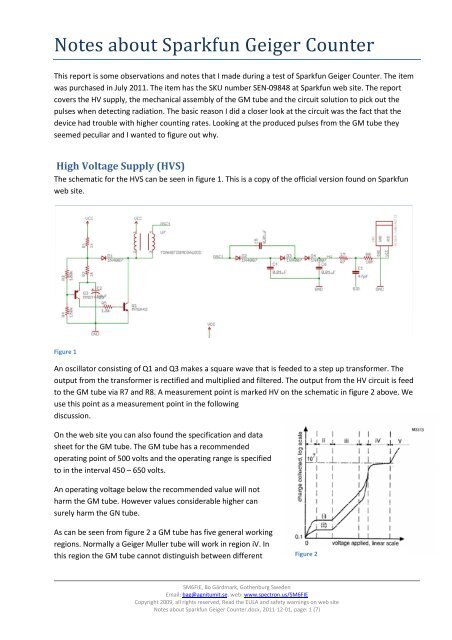
High Voltage Supply (HVS)<br />
The schematic for the HVS can be seen in figure 1. This is a copy of the official version found on <strong>Sparkfun</strong><br />
web site.<br />
Figure 1<br />
An oscillator consisting of Q1 and Q3 makes a square wave that is feeded to a step up transformer. The<br />
output from the transformer is rectified and multiplied and filtered. The output from the HV circuit is feed<br />
to the GM tube via R7 and R8. A measurement point is marked HV on the schematic in figure 2 above. We<br />
<strong>us</strong>e this point as a measurement point in the following<br />
disc<strong>us</strong>sion.<br />
On the web site you can also found the specification and data<br />
sheet for the GM tube. The GM tube has a recommended<br />
operating point of 500 volts and the operating range is specified<br />
to in the interval 450 – 650 volts.<br />
An operating voltage below the recommended value will not<br />
harm the GM tube. However values considerable higher can<br />
surely harm the GN tube.<br />
As can be seen from figure 2 a GM tube has five general working<br />
regions. Normally a <strong>Geiger</strong> Muller tube will work in region iV. In<br />
this region the GM tube cannot distinguish between different Figure 2<br />
SM6FIE, Bo Gärdmark, Gothenburg Sweden<br />
Email: bag@agnitumit.se, web: www.spectron.<strong>us</strong>/SM6FIE<br />
Copyright 2009, all rights reserved, Read the EULA and safety warnings on web site<br />
<strong>Notes</strong> <strong>about</strong> <strong>Sparkfun</strong> <strong>Geiger</strong> <strong>Counter</strong>.docx, 2011-12-01, page: 1 (7)
types of radiation but on the other hand the sensitivity is excellent due to the avalanche effect. Going up to<br />
region V further increases the avalanche effect and produces a total ionization of the gas between the<br />
electrodes. You can even reach a self-s<strong>us</strong>taining discharge that will continue as long as the voltage is<br />
applied by a single detection event. This region shall be avoided due to that operation here can/will<br />
degrade the tube in a longer perspective. Also, the pulse will not be as clean and nice as in region iV due to<br />
secondary avalanche ionizations effects.<br />
When reading the “tutorial” <strong>about</strong> the device I noted that the designer <strong>us</strong>ed a DVM (supposed to have an<br />
internal resistance of 10 MΩ) in series with a 10 MΩ resistor to measure the high voltage value. The<br />
measurement situation can be visualized as in figure 3.<br />
Rss<br />
Serial Resistor<br />
IL<br />
Uhvs<br />
Udvm<br />
Rhvs<br />
Rdvm<br />
Ehvs<br />
V<br />
Figure 3<br />
Here we have the following:<br />
HVS = High Voltage Supply<br />
DVM = Digital Voltmeter<br />
Rss = Serial Resistor connected in series with DVM<br />
Rhvs = Internal resistance of HVS<br />
Ehvs = True voltage of the HVS<br />
Uhvs = Measured voltage of the HVS at its terminal<br />
Udvm = Measured voltage of DVM<br />
Rdvm = Internal resistance of DVM<br />
IL = Current through DVM<br />
Applying Ohms law we will get the following:<br />
= ܮ݅<br />
ா௩௦<br />
ோ௩௦ାோ௦௦ାோௗ௩<br />
(1)<br />
Now according to the designer he/she did a measurement of the HVS voltage by <strong>us</strong>ing a 10 MΩ resistor<br />
(Rss) in series with the DVM. The DVM is assumed to have an internal resistance (Rdvm) of 10 MΩ. The<br />
measured value he/she did get according to the photo on the tutorial was 246 volts. The concl<strong>us</strong>ion was<br />
made that the HVS voltage was the double value of this due to the voltage divider of Rdvm and Rss. It was<br />
assumed that Rhvs (internal resistance of the HVS) was zero. See equation 2 and 3.<br />
SM6FIE, Bo Gärdmark, Gothenburg Sweden<br />
Email: bag@agnitumit.se, web: www.spectron.<strong>us</strong>/SM6FIE<br />
Copyright 2009, all rights reserved, Read the EULA and safety warnings on web site<br />
<strong>Notes</strong> <strong>about</strong> <strong>Sparkfun</strong> <strong>Geiger</strong> <strong>Counter</strong>.docx, 2011-12-01, page: 2 (7)
ோ௩௦ାோ௦௦ାோௗ௩ =ݏݒhܧ<br />
ோௗ௩<br />
(2) ݉ݒܷ݀ ∗<br />
ାଵାଵ =ݏݒhܧ<br />
∗ 246 ≈ 500 (3)<br />
ଵ<br />
Therefore the concl<strong>us</strong>ion was that the HVS voltage was <strong>about</strong> 500 volts. That value is also in accordance<br />
with the specifications for the GM tube.<br />
I did exactly the same measurement on my own device and got 241 Volts.<br />
But is this the correct value of the HVS voltage? Let’s assume that Rhvs is rather high like 25 MΩ. Going<br />
back to figure 3 we would have the following:<br />
= ௗ௩ ܮܫ<br />
ோௗ௩<br />
→ ଶସ<br />
(4) ܣߤ24.6 =<br />
ଵ<br />
The voltage drop due to the internal resistance of the HVS would be:<br />
(5) ݏݐ݈615ܸ = 25 ∗ 24.6 →ݏݒhܴ ∗ܮܫ =ݏݒhܷ −ݏݒhܧ<br />
The true value of the voltage of the HVS, Ehvs would then be:<br />
(6) ݏݐ݈1107ܸ = 246 + 246 + 615 =ݏݒhܧ<br />
Of course will the voltage that you measure dependent on the internal resistance Rdvm and the serial<br />
resistor Rss you <strong>us</strong>e. So what is the true value of the HVS voltage? Using a 1 Giga Ohms probe I measured a<br />
voltage of 1509 volts. I did a series of measurements with different resistors (load), se table1.<br />
Rl Up[V]<br />
10 346<br />
20 480<br />
30 573<br />
34,7 608<br />
39,4 639<br />
44,1 670<br />
48,8 699<br />
53,5 723<br />
58,2 747<br />
62,9 771<br />
67,6 791<br />
72,3 811<br />
82,3 852<br />
100 910<br />
139,4 1015<br />
182,3 1100<br />
1000 1509<br />
Table 1<br />
From this data we get a graph as in figure 4.<br />
SM6FIE, Bo Gärdmark, Gothenburg Sweden<br />
Email: bag@agnitumit.se, web: www.spectron.<strong>us</strong>/SM6FIE<br />
Copyright 2009, all rights reserved, Read the EULA and safety warnings on web site<br />
<strong>Notes</strong> <strong>about</strong> <strong>Sparkfun</strong> <strong>Geiger</strong> <strong>Counter</strong>.docx, 2011-12-01, page: 3 (7)
1600<br />
1500<br />
1400<br />
1300<br />
1200<br />
1100<br />
1000<br />
900<br />
800<br />
700<br />
600<br />
500<br />
400<br />
300<br />
200<br />
100<br />
0<br />
Up[V]<br />
0 100 200 300 400 500 600 700 800 900 1000 1100 1200<br />
Up[V]<br />
Log. (Up[V])<br />
Figure 4<br />
The blue line is a plot of the data points. The X axel is the resistive load in MΩ, the Y axel is the voltage in<br />
volts. The black line is a logarithmic curve with best fit to data points. As a note even 1 Giga Ohms seems to<br />
be loading the circuit too heavily due to the source internal resistance. However we are in much better<br />
position to draw concl<strong>us</strong>ion of the real value of the HVS voltage.<br />
The equation for the logarithmic curve is:<br />
(7) 313.41478 − ln(ܴ݈) ∗ 264.03422 = ܷ<br />
Here Up is the voltage of the HVS, Rl is the <strong>us</strong>ed load.<br />
The R2 fit of the curve is 0.99406 and that is a rather good fit.<br />
Now according to Thévenin's theorem we can calculate the internal resistance by measuring the open<br />
circuit voltage (no load) and then making a load that will give half the voltage of the open circuit voltage. By<br />
extrapolating the logarithmic curve in figure 4 we could make an assumption that the open circuit voltage<br />
of the HVS is <strong>about</strong> 1550 volts. Half of this value is 775 volts. Solving Rl for 775 volts from equation 7 gives<br />
an Rl of <strong>about</strong> 61 Mega Ohms.<br />
Now, the internal resistance of the HVS is not a linear curve of the load, the internal resistance is influenced<br />
by nonlinear elements like the diodes, the transformer etc. in circuit seen in figure 1. However it’s is a good<br />
indication of the magnitude of the HVS internal resistance. And you can do the concl<strong>us</strong>ion that the HVS<br />
voltage supplied to the GM tube is way above the specifications for the GM tube. This in turn will in a<br />
longer perspective degrade (damage) the GM tube.<br />
Going back to the designers notes you can conclude that the dynamic (load dependent) internal resistance<br />
was in the order of 41 Mega Ohms during the measurement. It fits pretty well with the curve in figure 4.<br />
SM6FIE, Bo Gärdmark, Gothenburg Sweden<br />
Email: bag@agnitumit.se, web: www.spectron.<strong>us</strong>/SM6FIE<br />
Copyright 2009, all rights reserved, Read the EULA and safety warnings on web site<br />
<strong>Notes</strong> <strong>about</strong> <strong>Sparkfun</strong> <strong>Geiger</strong> <strong>Counter</strong>.docx, 2011-12-01, page: 4 (7)
At the <strong>Sparkfun</strong> website you can find a comment <strong>about</strong> the HVS from member 115862. He measured the<br />
HVS to be 900 volts. He <strong>us</strong>ed a Fluke meter (with probably rather high input resistance ≈ 100 Mega Ohms).<br />
Also he has a fix to lower the voltage. He changed the value of C2, see figure 1, from 10 µF to 1 µF. After<br />
that he got a reading of 430 volts from the HVS. He probably still has an overvoltage of <strong>about</strong> 740 volts but<br />
doesn’t realize it. But he was definitively on the right track.<br />
GM Tube assembly<br />
The next issue that is with the device is the mounting of the GM tube. The GM tube has a Mica window in<br />
front. The mica window is very thin and fragile. You have to have a Mica window on your of you GM tube if<br />
you want to detect alpha radiation. The alpha particles consist of two protons and two neutrons bound<br />
together into a particle identical to a helium nucle<strong>us</strong>. Generally alpha particles have a low penetration<br />
depth. It will only reach a few centimeters in air and will be stopped by an ordinary paper. The walls of the<br />
GM tube are made of some metal; the alpha particles will not penetrate through them. Therefore the <strong>us</strong>e<br />
of a very thin Mica window in the front of the detector.<br />
To protect the Mica window on the detector a red plastic cap has been placed at the end of the tube. You<br />
have to remove this if you want to detect alpha particles from for example an AM241 source. However the<br />
mounting of the GM tube is made in a way that it is difficult to remove the cap and almost impossible to<br />
put it back again. This is a design flaw. The main problem is the zip-tie. The zip-tie is pulled very hard and<br />
that in turn make a mechanical pressure on the protection cap. Se figure 5. I have to order two new GM<br />
tubes to do a replacement.<br />
Figure 5<br />
A solution would be to remove the zip-tie and make some distance under the GM tube by adding a<br />
rectangle bit of Teflon etc. However this would mean that you have to remove the anode (center)<br />
connection of the tube and that in turn will give some mechanical stress to the tube. By experience I know<br />
that this could easily give small cracks in the isolation sealing of the anode.<br />
SM6FIE, Bo Gärdmark, Gothenburg Sweden<br />
Email: bag@agnitumit.se, web: www.spectron.<strong>us</strong>/SM6FIE<br />
Copyright 2009, all rights reserved, Read the EULA and safety warnings on web site<br />
<strong>Notes</strong> <strong>about</strong> <strong>Sparkfun</strong> <strong>Geiger</strong> <strong>Counter</strong>.docx, 2011-12-01, page: 5 (7)
So after doing some test with the mica window removed I tried to put on the cap again, and Zap, I didn’t<br />
barely touch the mica window in my attempts to put the cap back again but the mica window imploded and<br />
the GM tube was destroyed.<br />
It is interesting to note that in the earlier incarnations of the device the GM tube was mounted in a way so<br />
that the end of the tube was over the edge of the circuit board. Unfortunately <strong>Sparkfun</strong> did a change of this<br />
when redesigning the PCB. You can see this more convenient design on some pictures on the tutorial on<br />
<strong>Sparkfun</strong> web site. The best solution would be to have some sort of distance under the tube so you easily<br />
could remove and install the protection cap.<br />
GM Tube detector Circuit<br />
The device detector circuit is very rudimentary. It does it suffer from the overvoltage feed which lead to<br />
long dead and recovery time for the tube (disc<strong>us</strong>sed in the section above). The long dead and recovery time<br />
means that it takes a long time before the tube has recovered from an ionization event and is prepared to<br />
register a new event. This in turn leads to that the device is only capable to very low count rates, not in<br />
accordance with the specifications from the manufacturer.<br />
Figure 6<br />
With a correct High Voltage you will get a pulse similar to that in figure 1 above. On the other hand if you<br />
supply a voltage far above the recommended operating voltage you will get a “pulse” similar to the one<br />
ill<strong>us</strong>trated in figure 2 below.<br />
Figure 7<br />
SM6FIE, Bo Gärdmark, Gothenburg Sweden<br />
Email: bag@agnitumit.se, web: www.spectron.<strong>us</strong>/SM6FIE<br />
Copyright 2009, all rights reserved, Read the EULA and safety warnings on web site<br />
<strong>Notes</strong> <strong>about</strong> <strong>Sparkfun</strong> <strong>Geiger</strong> <strong>Counter</strong>.docx, 2011-12-01, page: 6 (7)
Another issue is that the circuit solution is not the best on several other aspects.<br />
1. The anode resistor shall be placed as close to the anode as possible th<strong>us</strong> reducing the capacitance<br />
added to the anode. J<strong>us</strong>t 20 mm of anode lead can double the effect of dead time for the tube. It<br />
also important for maintaining the plateau length, minimize discharge currents and maximize the<br />
tube life. This consideration has not been taken into account on the current design.<br />
2. The RC (R10/C9) network <strong>us</strong>ed in the detector circuit is far too big. It gives a time constant of <strong>about</strong><br />
8 mille seconds. In practice perhaps even the double value of this. This in turn limits the maximum<br />
count frequency to <strong>about</strong> 60 pulses per seconds. The actual GM tube can perform much better<br />
than that. I s<strong>us</strong>pect that this is a design compensation due to the problem with the HVS described<br />
above. You cure the problem by the symptom rather than go to the root ca<strong>us</strong>e.<br />
3. Best practice is to take out the counting signal from the cathode. Taken the signal from the anode<br />
will feed the power supply noise (switch noise) into the measurement circuit. At device switch on<br />
there will be a sharp transient pulse feed into the measurement circuit. Using a cathode circuit also<br />
eliminates the <strong>us</strong>e of a high voltage blocking capacitor. Any extra capacitance added to the cathode<br />
has considerable lower effect compared to adding it to the anode side of the tube.<br />
4. Last, but this is perhaps to demand too much. By adding a few components it will be possible to get<br />
a much higher counting rate. The trick is to <strong>us</strong>e a discriminator and a differentiator circuit. By doing<br />
that and gating the two signals together even closely spaced pulses (common at high CPS) will be<br />
correctly counted.<br />
<strong>Notes</strong> added 2011-08-25<br />
I did replace GM LND712 tube with a 6107/BS212 GM tube. The specifications for 6107/BS212 GM tube<br />
have a recommended operating voltage of 620-720 volts. At zero count rate the current consumption will<br />
be zero µA and at very high count rate <strong>about</strong> 7-8 µA.<br />
At zero count rate I measured the HV supply of <strong>Sparkfun</strong> <strong>Geiger</strong> Meter to be <strong>about</strong> 1500 volts. At very high<br />
count rate (the 6107/BS212 GM tube is very sensitive to Alfa radiation) the high voltage did drop to <strong>about</strong><br />
1000 volts. Going back to table 1 we get the closest figure to 1000 volts to be 1015 volts. This is for a load<br />
of 139.4 MΩ. The current is therefore <strong>about</strong> 1015/139.4 ≈7.3 µA. A good fit with the specifications for the<br />
GM tube. Looking at the output pulse at high count rates I also noted that they were distorted. The<br />
concl<strong>us</strong>ion is that this is due to overvoltage of the tube. Overvoltage gives avalanche effects and produces<br />
partial total ionization of the tube (and will in a longer perspective degrade the tube).<br />
I finally constructed my own stabilized HV power supply. I wanted to eliminate the big changes in voltage<br />
between a low count rate and a high count rates (see above). The change in voltage is <strong>about</strong> nine volts<br />
from zero count rates to full count rate.<br />
Bo, SM6FIE<br />
References:<br />
www.spectron.<strong>us</strong>/SM6FIE/Electronics/HvProbe/High_Voltage_Probe.pdf<br />
SM6FIE, Bo Gärdmark, Gothenburg Sweden<br />
Email: bag@agnitumit.se, web: www.spectron.<strong>us</strong>/SM6FIE<br />
Copyright 2009, all rights reserved, Read the EULA and safety warnings on web site<br />
<strong>Notes</strong> <strong>about</strong> <strong>Sparkfun</strong> <strong>Geiger</strong> <strong>Counter</strong>.docx, 2011-12-01, page: 7 (7)