Handbook for the Starlight Xpress SXV AO unit
Handbook for the Starlight Xpress SXV AO unit
Handbook for the Starlight Xpress SXV AO unit

Create successful ePaper yourself
Turn your PDF publications into a flip-book with our unique Google optimized e-Paper software.
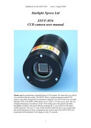
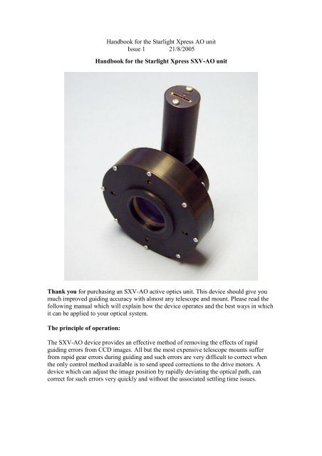
<strong>Handbook</strong> <strong>for</strong> <strong>the</strong> <strong>Starlight</strong> <strong>Xpress</strong> <strong>AO</strong> <strong>unit</strong>Issue 1 21/8/2005<strong>Handbook</strong> <strong>for</strong> <strong>the</strong> <strong>Starlight</strong> <strong>Xpress</strong> <strong>SXV</strong>-<strong>AO</strong> <strong>unit</strong>Thank you <strong>for</strong> purchasing an <strong>SXV</strong>-<strong>AO</strong> active optics <strong>unit</strong>. This device should give youmuch improved guiding accuracy with almost any telescope and mount. Please read <strong>the</strong>following manual which will explain how <strong>the</strong> device operates and <strong>the</strong> best ways in whichit can be applied to your optical system.The principle of operation:The <strong>SXV</strong>-<strong>AO</strong> device provides an effective method of removing <strong>the</strong> effects of rapidguiding errors from CCD images. All but <strong>the</strong> most expensive telescope mounts sufferfrom rapid gear errors during guiding and such errors are very difficult to correct when<strong>the</strong> only control method available is to send speed corrections to <strong>the</strong> drive motors. Adevice which can adjust <strong>the</strong> image position by rapidly deviating <strong>the</strong> optical path, cancorrect <strong>for</strong> such errors very quickly and without <strong>the</strong> associated settling time issues.
<strong>Handbook</strong> <strong>for</strong> <strong>the</strong> <strong>Starlight</strong> <strong>Xpress</strong> <strong>AO</strong> <strong>unit</strong>Issue 1 21/8/2005The most common method of shifting an image <strong>for</strong> <strong>AO</strong> purposes is to use a ‘tip-tilt’mirror to reflect <strong>the</strong> beam through a variable angle. This works well, but deviates <strong>the</strong>optical path through 90 degrees and takes up a considerable back focal distance. Itsmotion sensitivity is also affected by <strong>the</strong> distance between <strong>the</strong> mirror and <strong>the</strong> CCD. A‘straight though’ device is more convenient and optically shorter, so <strong>the</strong> SX <strong>unit</strong> wasdesigned with this in mind. A secondary advantage of <strong>the</strong> straight through design is that itis possible to construct a system that has a well defined optical deviation <strong>for</strong> a definedinput signal. This means that <strong>the</strong> ‘sensitivity’ of <strong>the</strong> system in pixels shift per input step isessentially constant and is independent of <strong>the</strong> optical system used and <strong>the</strong> distancebetween <strong>the</strong> CCD and <strong>AO</strong>.The <strong>AO</strong> element is a Multi-coated AR bloomed plane-parallel optical window with athickness of 12mm and a diameter of 40mm. This element can be tilted by up toapproximately +/- 3 degrees, by rotating four small stepper motors at <strong>the</strong> periphery of <strong>the</strong>aluminium carrier plate. Converging light from <strong>the</strong> telescope objective lens or mirror,passes through <strong>the</strong> window on its way to <strong>the</strong> CCD chip, but is essentially unaffectedwhen <strong>the</strong> window is perpendicular to <strong>the</strong> beam. However, when <strong>the</strong> window is tilted, <strong>the</strong>converging beam is displaced by an amount which can be defined as approximately0.075mm per 1 degree of tilt. The maximum image deviation is <strong>the</strong>re<strong>for</strong>e approximately+/- 0.15mm in both <strong>the</strong> X and Y planes. This corresponds to about +/- 23 pixels on <strong>the</strong>CCD of an <strong>SXV</strong>-H9 camera.The <strong>AO</strong> <strong>unit</strong> is usually controlled by serial data from an RS232 port. This port can be oneof those provided on most PCs, or <strong>the</strong> serial interface of an <strong>SXV</strong> camera (if supported by<strong>the</strong> software package in use). A USB to serial adaptor can also be used on a PC withoutnative serial ports. The serial data input of <strong>the</strong> <strong>AO</strong> is an RJ11 socket and so a lead with anRJ11 to 9 pin ‘D’ style socket is provided to enable connection to a standard serial port.The computer port should be set to 9600B, 8 bits data, 1 stop bit, no parity.A typical application of <strong>the</strong> <strong>AO</strong> <strong>unit</strong> <strong>for</strong> off-axis guiding:The following diagram shows how <strong>the</strong> <strong>AO</strong> <strong>unit</strong> may be used with <strong>the</strong> optional off-axisguider (OAG) and an SX CCD camera. This is likely to be <strong>the</strong> normal configuration <strong>for</strong>most imagers, as it offers accurate guiding which is free of flexure and mirror shiftproblems. The OAG consists of a short aluminium barrel with a pick-off prism whichfeeds light to an <strong>SXV</strong> guide camera, mounted at <strong>the</strong> end of a short extension tube. Theguide camera position is designed to be close to <strong>the</strong> correct focal distance when a<strong>Starlight</strong> <strong>Xpress</strong> camera is mounted on <strong>the</strong> main optical output of <strong>the</strong> OAG and broughtinto focus. Any small errors may be corrected by loosening <strong>the</strong> two set screws in <strong>the</strong>threaded collar and sliding <strong>the</strong> camera into <strong>the</strong> correct position.The OAG is attached to <strong>the</strong> <strong>AO</strong> <strong>unit</strong> by two set screws which engage with a grooved ringat <strong>the</strong> output of <strong>the</strong> <strong>AO</strong> assembly. Please note that <strong>the</strong> guider barrel should be oriented sothat it projects along <strong>the</strong> line which joins <strong>the</strong> North and South motors. When locatedproperly, <strong>the</strong> two RJ11 sockets on <strong>the</strong> <strong>AO</strong> will be at <strong>the</strong> bottom of <strong>the</strong> <strong>unit</strong>, diametricallyopposite to <strong>the</strong> guider barrel. The long axis of <strong>the</strong> CCD in <strong>the</strong> guide camera should be
<strong>Handbook</strong> <strong>for</strong> <strong>the</strong> <strong>Starlight</strong> <strong>Xpress</strong> <strong>AO</strong> <strong>unit</strong>Issue 1 21/8/2005oriented so that it is parallel to <strong>the</strong> <strong>AO</strong> backplate. This can be seen in <strong>the</strong> picture at <strong>the</strong>front of this handbook, as indicated by <strong>the</strong> orientation of <strong>the</strong> guide camera socket.The imaging camera is attached to <strong>the</strong> rear of <strong>the</strong> OAG, using a suitable adaptor ring.Two types are supplied – one with a ‘T’ thread <strong>for</strong> <strong>the</strong> <strong>SXV</strong>-H9/9C and M25C and onewith an M42 thread <strong>for</strong> <strong>the</strong> rest of <strong>the</strong> SX range. The orientation of <strong>the</strong> camera is adjustedby loosening <strong>the</strong> two set screws and rotating <strong>the</strong> ring into <strong>the</strong> required position. As <strong>the</strong>camera is not involved with collecting guiding in<strong>for</strong>mation, it may be set at any angle.However, <strong>the</strong> pick off prism may cause shadowing if <strong>the</strong> long axis of a large chip is set in<strong>the</strong> vertical plane.Both <strong>the</strong> <strong>AO</strong> <strong>unit</strong> and <strong>the</strong> OAG have recesses which will take a 48mm filter. When using<strong>the</strong> OAG, it is an advantage to use <strong>the</strong> recess inside <strong>the</strong> camera mounting ring, so that <strong>the</strong>guide camera sensitivity is not compromised by any filters that you may add. This is
<strong>Handbook</strong> <strong>for</strong> <strong>the</strong> <strong>Starlight</strong> <strong>Xpress</strong> <strong>AO</strong> <strong>unit</strong>Issue 1 21/8/2005especially useful if you image with narrow band filters, such as H-alpha. A light pollutionrejection filter, such as an IDAS P1 or P2 might be best added at <strong>the</strong> output of <strong>the</strong> <strong>AO</strong><strong>unit</strong>, where it will improve <strong>the</strong> guide star contrast, as well as improving your cameraimages. Note that <strong>the</strong> recesses are not threaded and so you should be careful that a filterdoes not fall out and get damaged when dismantling <strong>the</strong> <strong>unit</strong>.N.B. Although <strong>the</strong> <strong>SXV</strong>-<strong>AO</strong> was designed <strong>for</strong> operation with an SX camera, it ispossible to attach o<strong>the</strong>r imagers with an appropriate adaptor and still use <strong>the</strong> <strong>AO</strong> via oneof our USB2 interface boxes. The USB2 interface provides a convenient way to read andcontrol <strong>the</strong> <strong>SXV</strong> guide camera, even when no SX main imager is in use. You will need toorganise <strong>the</strong> alternative camera spacing so that it may be brought to focus simultaneouslywith <strong>the</strong> guide camera.Connecting up <strong>the</strong> <strong>AO</strong> electronics <strong>for</strong> off-axis guiding:The method of connection will vary slightly, depending on <strong>the</strong> guiding software in useand <strong>the</strong> equipment available. The SX software and AstroArt allow you to use <strong>the</strong> <strong>SXV</strong>port divider box <strong>for</strong> serial control of <strong>the</strong> <strong>AO</strong> <strong>unit</strong> and so you might prefer to use thismethod to cut down on <strong>the</strong> number of cables required. At <strong>the</strong> time of writing, Maxim DLdoes not offer an option to connect via <strong>the</strong> divider box and so a serial cable from <strong>the</strong> PCCOM port will be required if you use Maxim. PCs with no COM port can use acommercially available USB to serial interface <strong>for</strong> <strong>the</strong> connection.1) Connect <strong>the</strong> serial to RJ11 cable (supplied) into <strong>the</strong> <strong>AO</strong> <strong>unit</strong> input socket.2) Connect <strong>the</strong> RJ11 to guider port cable (supplied) from <strong>the</strong> <strong>AO</strong> output to <strong>the</strong> guiderinput on <strong>the</strong> mount. This cable is not essential, but it allows <strong>the</strong> software to‘bump’ <strong>the</strong> mount when <strong>the</strong> errors become too large <strong>for</strong> <strong>the</strong> <strong>AO</strong> <strong>unit</strong>. Most lowercostmount users will find it necessary <strong>for</strong> long exposure times.3) Connect <strong>the</strong> guide camera to <strong>the</strong> socket on <strong>the</strong> <strong>SXV</strong> imaging camera, or <strong>the</strong> socketon <strong>the</strong> <strong>SXV</strong> interface box (used with older parallel port imaging cameras, or whenimaging with o<strong>the</strong>r makes of camera). Include <strong>the</strong> port divider box in this cable, ifyou intend to use this <strong>for</strong> serial control (Fig 1).4) Connect <strong>the</strong> serial to RJ11 cable to <strong>the</strong> appropriate port divider output, or to <strong>the</strong>RS232 cable from your PC (Fig 2).5) Connect <strong>the</strong> <strong>AO</strong> power lead to <strong>the</strong> power supply block.
<strong>Handbook</strong> <strong>for</strong> <strong>the</strong> <strong>Starlight</strong> <strong>Xpress</strong> <strong>AO</strong> <strong>unit</strong>Issue 1 21/8/2005.Fig 1Fig 2
<strong>Handbook</strong> <strong>for</strong> <strong>the</strong> <strong>Starlight</strong> <strong>Xpress</strong> <strong>AO</strong> <strong>unit</strong>Issue 1 21/8/2005Connecting up <strong>the</strong> <strong>AO</strong> electronics <strong>for</strong> STAR2000 guiding:STAR2000 guiding does not require <strong>the</strong> OAG <strong>unit</strong> and <strong>the</strong> camera may be attacheddirectly to <strong>the</strong> <strong>AO</strong>. As with off-axis guiding, <strong>the</strong>re is more than one way to connect up <strong>the</strong><strong>AO</strong> <strong>for</strong> STAR2000 use. Figure 3 shows <strong>the</strong> most likely way <strong>for</strong> most users to connect <strong>for</strong>serial control via <strong>the</strong> PC. O<strong>the</strong>r alternatives include serial control via a port divider on an<strong>SXV</strong> output and parallel control from <strong>the</strong> RJ11 guider output of an <strong>SXV</strong> camera.General pointers:Fig 3When <strong>the</strong> <strong>AO</strong> <strong>unit</strong> is first attached to <strong>the</strong> telescope, it is necessary to arrange <strong>the</strong> off-axisguide camera, or <strong>the</strong> STAR2000 camera, so that <strong>the</strong> East – West <strong>AO</strong> axis is parallel to <strong>the</strong>long axis of <strong>the</strong> guide image. This is easily done by viewing <strong>the</strong> guider or camera chipthrough <strong>the</strong> front of <strong>the</strong> <strong>AO</strong> window. Hold <strong>the</strong> <strong>AO</strong> <strong>unit</strong> so that <strong>the</strong> two RJ11 sockets areat <strong>the</strong> bottom and ensure that <strong>the</strong> guider chip is visible as a horizontal rectangle as seen in<strong>the</strong> off-axis prism. A STAR2000 camera chip should also appear as a horizontal rectanglein this view.
<strong>Handbook</strong> <strong>for</strong> <strong>the</strong> <strong>Starlight</strong> <strong>Xpress</strong> <strong>AO</strong> <strong>unit</strong>Issue 1 21/8/2005The <strong>SXV</strong>-<strong>AO</strong> can execute an image position correction in a few milliseconds, but <strong>the</strong>effective correction rate is limited by <strong>the</strong> brightness of <strong>the</strong> guide star and <strong>the</strong> downloadspeed of <strong>the</strong> guide camera image. For best results with a poor telescope mount, you needto choose as bright a star as possible and use a small guide window. Binning <strong>the</strong> guidecamera image will also help.The orientation of <strong>the</strong> <strong>AO</strong> assembly is normally arranged so that <strong>the</strong> East-West RA driftdirection is along <strong>the</strong> long axis of <strong>the</strong> guider chip. However, <strong>the</strong>re is no reason to con<strong>for</strong>mto this if <strong>the</strong> mount corrections can cope with <strong>the</strong> non-standard orientation. In this case,you can rotate <strong>the</strong> entire <strong>unit</strong> about <strong>the</strong> optical axis <strong>for</strong> optimising <strong>the</strong> image orientationor <strong>for</strong> finding a suitable guide star.When attaching <strong>the</strong> <strong>AO</strong> <strong>unit</strong> to a T thread adaptor, be careful to ensure that <strong>the</strong> malethread does not project into <strong>the</strong> <strong>AO</strong> body. Any projection can interfere with <strong>the</strong>movement of <strong>the</strong> image displacer and may jam <strong>the</strong> <strong>unit</strong>. If <strong>the</strong> thread is too long, add athin card or plastic washer between <strong>the</strong> adaptor and <strong>AO</strong> front plate.
<strong>Handbook</strong> <strong>for</strong> <strong>the</strong> <strong>Starlight</strong> <strong>Xpress</strong> <strong>AO</strong> <strong>unit</strong>Issue 1 21/8/2005During extreme movement of <strong>the</strong> displacer, <strong>the</strong> motors may encounter excessive frictionand fail to start. The ‘centre’ command will normally overcome this, as it switches to amuch lower speed, high-torque stepping rate after 5 seconds of failure to move. However,in <strong>the</strong> worst case, you can rotate <strong>the</strong> motors manually by inserting a small screwdriverthrough <strong>the</strong> holes in <strong>the</strong> front plate. Be careful not to rotate <strong>the</strong>m too far, as only 4 turns isrequired to move <strong>the</strong> drive through its entire range. Adjust each motor until its shaftrotates as freely as possible be<strong>for</strong>e using <strong>the</strong> ‘centre’ command again.Using <strong>the</strong> <strong>AO</strong> system:The following instructions are based on <strong>the</strong> software provided by <strong>Starlight</strong> <strong>Xpress</strong> andwill be different <strong>for</strong> o<strong>the</strong>r control programs. Please read <strong>the</strong> relevant help files if you areusing AstroArt or Maxim DL. I also assume that you are using <strong>the</strong> off-axis guider andserial control of <strong>the</strong> <strong>AO</strong>.Open <strong>the</strong> camera software and check that it recognises <strong>the</strong> presence of your main camera.Now open <strong>the</strong> ‘Set program defaults’ menu (under ‘File’) and check that <strong>the</strong> serial controlsettings are appropriate to your system. For instance, if you are using a serial port on <strong>the</strong>PC to drive <strong>the</strong> <strong>AO</strong> <strong>unit</strong>, check <strong>the</strong> ‘<strong>AO</strong> <strong>unit</strong> available’ check box and <strong>the</strong>n set <strong>the</strong> PCCOM port number. The ‘Select half rate’ box is to slow down <strong>the</strong> mount corrections thatwill occur if <strong>the</strong> <strong>AO</strong> <strong>unit</strong> exceeds its useful range. You may find this useful if you have amount with ra<strong>the</strong>r erratic drives, such as an SCT on a <strong>for</strong>k mount. Now save <strong>the</strong> programdefaults and return to <strong>the</strong> main program window.Select <strong>the</strong> main camera icon (4 from <strong>the</strong> left) and use a short exposure time to see if <strong>the</strong>reare any stars visible. Adjust <strong>the</strong> main telescope focus until you have a well focused starfield in <strong>the</strong> main camera image.Now click on <strong>the</strong> ‘Autoguider’ icon (5 from <strong>the</strong> left) and you will see <strong>the</strong> guider windowand control panel. Select a 1 second exposure time and move <strong>the</strong> ‘Stretch image’ slider to‘Maximum’. Press <strong>the</strong> ‘Start’ button and you should see a guide camera image appear in<strong>the</strong> image window. At this point, <strong>the</strong>re may be no stars visible, as <strong>the</strong> guider focusingmight be seriously in error. If no stars are seen, try increasing <strong>the</strong> guide exposure to 3 ormore seconds until you can detect some stars. Now use <strong>the</strong> Allen key provided to loosen<strong>the</strong> two set screws in <strong>the</strong> guider retaining collar and <strong>the</strong>n gently slide <strong>the</strong> guiderbackwards and <strong>for</strong>wards until a sharp star image is seen. Note that <strong>the</strong> image might bedistorted by <strong>the</strong> telescope optics, as it is well ‘off axis’. Once focused, re-lock <strong>the</strong> collarin place, making sure that <strong>the</strong> guide camera orientation is with <strong>the</strong> input plug parallel to<strong>the</strong> <strong>AO</strong> backplate. Briefly blip one of <strong>the</strong> RA buttons on your telescope handset andensure that <strong>the</strong> stars drift parallel to <strong>the</strong> long axis of <strong>the</strong> guider window – if not, rotate <strong>the</strong>entire <strong>AO</strong> assembly about <strong>the</strong> telescope axis until <strong>the</strong>y do so. Now check that <strong>the</strong> <strong>AO</strong>mode is set <strong>for</strong> ‘serial’ and make sure that you have selected <strong>the</strong> correct <strong>AO</strong> control portif you are using <strong>the</strong> splitter box (ser1 or ser2). Press <strong>the</strong> ‘Use default’ to temporarily set<strong>the</strong> guiding speed of <strong>the</strong> <strong>AO</strong>. You now have <strong>the</strong> system ready to test, so proceed asfollows:
<strong>Handbook</strong> <strong>for</strong> <strong>the</strong> <strong>Starlight</strong> <strong>Xpress</strong> <strong>AO</strong> <strong>unit</strong>Issue 1 21/8/2005Find an interesting object or starfield to image and adjust <strong>the</strong> ‘scope until a convenientguide star can be seen in <strong>the</strong> guider field. Ideally, <strong>the</strong> star should be easily seen in anexposure of only 0.1 seconds and, if necessary, binning may be used to gain sensitivity.Once <strong>the</strong> guide star is identified, press <strong>the</strong> ‘Centralise <strong>AO</strong>’ button and watch <strong>the</strong> starimage – it should cycle through a cross shaped figure and <strong>the</strong>n settle after about 2seconds. Now press ‘Select guide star’ and click on <strong>the</strong> star which you think best suitedto act as your guide reference (bright and isolated). You can now press <strong>the</strong> ‘Train’ buttonand <strong>the</strong> <strong>AO</strong> will cycle automatically while measuring <strong>the</strong> system sensitivity. If <strong>the</strong>training cycle is successful, new rate values will be generated, although <strong>the</strong>y willprobably be much <strong>the</strong> same as <strong>the</strong> default values. If <strong>the</strong> calibration fails, it will probablybe due to one or both of <strong>the</strong> <strong>AO</strong> direction settings being wrong. The defaults in <strong>the</strong>software are <strong>for</strong> a guide camera mounted as shown in <strong>the</strong> frontispiece picture of <strong>the</strong> <strong>AO</strong>assembly, with its indicator LED towards <strong>the</strong> camera end of <strong>the</strong> <strong>AO</strong> barrel. You canei<strong>the</strong>r rotate <strong>the</strong> guide camera to this position, or try swapping <strong>the</strong> <strong>AO</strong> up/down andleft/right check box settings. Once you have <strong>the</strong> directions set and <strong>the</strong> motion ratesdetermined, calibration of <strong>the</strong> <strong>AO</strong> will not be necessary in future sessions as it is aconstant factor <strong>for</strong> all ‘scopes. Only one o<strong>the</strong>r setting is still necessary. This is <strong>the</strong>calibration of <strong>the</strong> mount <strong>for</strong> ‘mount bumps’ during your guiding session. Although <strong>the</strong><strong>AO</strong> can take care of <strong>the</strong> small and rapid guiding errors, <strong>the</strong>re will be steady drifts of <strong>the</strong>telescope drive which will slowly shift <strong>the</strong> <strong>AO</strong> to <strong>the</strong> limits of its motion range. Tocombat this effect, we need to send occasional corrections to <strong>the</strong> mount (‘bumps’) inorder that <strong>the</strong> <strong>AO</strong> remains near to <strong>the</strong> centre of its operating range. A relatively easy wayin which to determine <strong>the</strong> settings required is to set <strong>the</strong> <strong>AO</strong> guiding on your selectedguide star (press ‘Start guiding’) and <strong>the</strong>n use <strong>the</strong> hand controller to move <strong>the</strong> star slightlyEast or West until <strong>the</strong> data boxes on <strong>the</strong> guider image start to show offset values of morethan 50 steps. At this point you will see <strong>the</strong> text ‘Move mount’ appear, along with adirection indication. If <strong>the</strong> result is that <strong>the</strong> <strong>AO</strong> error falls rapidly below 50 steps, <strong>the</strong>n <strong>the</strong>mount direction and rate is about right, but any sign that <strong>the</strong> error is rapidly increasingwill show that <strong>the</strong> ‘Swap e/w’ or n/s direction is incorrect. Stop <strong>the</strong> guiding, reverse <strong>the</strong>‘Swap’ box <strong>for</strong> that direction and try guiding again. Once you have both directions setcorrectly, you can experiment with <strong>the</strong> mount speed (pixels per second) settings tooptimise <strong>the</strong> amount of correction applied – ideally you want <strong>the</strong> mount correction tomove <strong>the</strong> <strong>AO</strong> back to <strong>the</strong> ‘zero offset’ position, but <strong>the</strong>re is a large tolerance on this.You are now ready to take an <strong>AO</strong> guided image!Re-centralise <strong>the</strong> <strong>AO</strong> <strong>unit</strong>, select your guide star and <strong>the</strong>n press ‘Start guiding’. Once <strong>the</strong>guide star image is stable, press <strong>the</strong> main camera icon and set your image exposure timein that dialog box. Now press ‘Take photo’ and wait <strong>for</strong> <strong>the</strong> result to appear!Updating <strong>the</strong> <strong>AO</strong> firmware:From time to time, improved versions of <strong>the</strong> <strong>AO</strong> firmware will become available and willbe posted on <strong>the</strong> <strong>Starlight</strong> <strong>Xpress</strong> web site. The <strong>AO</strong> <strong>unit</strong> is provided with a means ofupdating its internal firmware via <strong>the</strong> PC serial port. You will need <strong>the</strong> serial cable asprovided with <strong>the</strong> <strong>AO</strong> <strong>unit</strong> and this should be connected between <strong>the</strong> <strong>AO</strong> <strong>unit</strong> input
<strong>Handbook</strong> <strong>for</strong> <strong>the</strong> <strong>Starlight</strong> <strong>Xpress</strong> <strong>AO</strong> <strong>unit</strong>Issue 1 21/8/2005socket and <strong>the</strong> serial port of your PC. The updating procedure also requires <strong>the</strong> powersupply to be connected to <strong>the</strong> <strong>AO</strong>.1) Download <strong>the</strong> latest version of <strong>the</strong> updater software fromhttp://www.starlight-xpress.co.uk/<strong>SXV</strong>-<strong>AO</strong>.htm2) Uninstall any previous version of <strong>AO</strong> Updater using <strong>the</strong> Add/Remove Programs in <strong>the</strong>Control Panel.3) Install <strong>AO</strong> Updater software by executing <strong>the</strong> ‘Setup.exe’ file.4) Connect <strong>AO</strong> to a PC serial communications port (COM1 is default).5) Power up <strong>the</strong> <strong>AO</strong> <strong>unit</strong>.6) Start <strong>the</strong> <strong>AO</strong>Updater program by clicking on <strong>the</strong> screen icon.7) If you are not using COM1 <strong>the</strong>n use <strong>the</strong> Settings menu to select ano<strong>the</strong>r COM port.8) Press <strong>the</strong> CONNECT button (if unsuccessful <strong>the</strong>n refer to <strong>the</strong> HELP file).9) Press <strong>the</strong> SELECT button and OPEN <strong>the</strong> activoxxx.hex file (xxx = version number).The default directory <strong>for</strong> <strong>the</strong> hex file isC:\Program Files\<strong>Starlight</strong> <strong>Xpress</strong>\<strong>AO</strong>updater\Hex\10) Press <strong>the</strong> UPDATE button and wait <strong>for</strong> about 60 seconds to complete <strong>the</strong>programming. The ‘Petrol gauge’ bar will show <strong>the</strong> state of progress. Do not open orswitch to any o<strong>the</strong>r applications while programming is taking place!11) Once successfully updated, exit <strong>the</strong> <strong>AO</strong> Updater program and turn <strong>the</strong> power to <strong>the</strong><strong>AO</strong> OFF. Wait 5 seconds <strong>the</strong>n switch <strong>the</strong> power back ON. The <strong>AO</strong> is now ready <strong>for</strong> use.The Active optics command set.This in<strong>for</strong>mation is provided <strong>for</strong> users who wish to write <strong>the</strong>ir own control programs.The serial mode command listChar Char Char Char Char Char Char Result Return1 2 3 4 5 6 7K Find Centre KG N 0 0 0 0 1 <strong>AO</strong> 1 step North G or L(hit limit)G S 0 0 0 0 1 <strong>AO</strong> 1 step South G or L(hit limit)G T 0 0 0 0 1 <strong>AO</strong> 1 step East G or L
<strong>Handbook</strong> <strong>for</strong> <strong>the</strong> <strong>Starlight</strong> <strong>Xpress</strong> <strong>AO</strong> <strong>unit</strong>Issue 1 21/8/2005(hit limit)G W 0 0 0 0 1 <strong>AO</strong> 1 step West G or L(hit limit)M N 0 0 0 0 1 Mount 1 step N MM S 0 0 0 0 1 Mount 1 step S MM T 0 0 0 0 1 Mount 1 step E MM W 0 0 0 0 1 Mount 1 step W MRLCentre at lowspeed (unjam)Get Limit switchstatusKCharacterwith an ASCIIvalue between0x30 and0x3FV + 3 digitsVCode versionnumberX Handshake YU Update firmware U = Success,Z = FailParallel mode - <strong>the</strong> pulse width input specificationIn pulse width mode, <strong>the</strong> input is a pulse width encoded signal with four direction linesand a common ground, similar to that used <strong>for</strong> telescope mount control. However, <strong>the</strong>pulse width per motor step is greatly reduced, so as to minimise <strong>the</strong> response time. Theminimum control pulse width is 10mS, which steps by 1 step in <strong>the</strong> appropriate direction.Longer pulses follow in a linear progression, increasing by 1 motor step <strong>for</strong> each 10mSincremental increase in pulse length. Note that only ONE input can be low at any onetime, o<strong>the</strong>rwise o<strong>the</strong>r control functions may be inadvertently initiated.Various different functions can be triggered by ‘abnormal’ input pulse patterns. The mostuseful of <strong>the</strong>se is <strong>the</strong> ‘centre’ mode, which should be used be<strong>for</strong>e beginning any guidingsequence. In this, <strong>the</strong> inputs are all taken low and <strong>the</strong>n simultaneously released. The <strong>AO</strong><strong>unit</strong> will <strong>the</strong>n rapidly cycle between its limit switches and adjust <strong>the</strong> window to becentred in <strong>the</strong> dynamic range and normal to <strong>the</strong> incoming light. O<strong>the</strong>r functions include<strong>the</strong> transmission of commands through <strong>the</strong> <strong>AO</strong> system to <strong>the</strong> mount (<strong>for</strong> ‘bumping’ <strong>the</strong>mount position) and various setup modes, mostly used <strong>for</strong> calibration during assembly.Please note that mount commands in serial mode can take place while fur<strong>the</strong>r <strong>AO</strong>commands are being received and acted upon. This allows <strong>the</strong> <strong>AO</strong> <strong>unit</strong> to follow <strong>the</strong>mount correction and ‘back off’ <strong>the</strong> <strong>AO</strong> error without trailing <strong>the</strong> image. This is notavailable in parallel mode at <strong>the</strong> present time, but may be added later. Be careful not tosend multiple commands without allowing time <strong>for</strong> <strong>the</strong> previous one to complete.
<strong>Handbook</strong> <strong>for</strong> <strong>the</strong> <strong>Starlight</strong> <strong>Xpress</strong> <strong>AO</strong> <strong>unit</strong>Issue 1 21/8/2005The command list <strong>for</strong> parallel modePlease note that negative logic is used <strong>for</strong> all commands – an ‘active’ input is pulleddown to <strong>the</strong> ground (0v) rail. The directions of movement are based on an inverted imageand with <strong>the</strong> <strong>AO</strong> <strong>unit</strong> arranged with its North-South axis at 90 degrees to <strong>the</strong> Declinationaxis.Guiding functionsEast North South West Function0 0 0 0 Find Centre /Switch fromserial to parallelmode1 1 1 0 <strong>AO</strong> West1 1 0 1 <strong>AO</strong> South1 0 1 1 <strong>AO</strong> North0 1 1 1 <strong>AO</strong> East0 0 0 1 Mount West0 0 1 0 Mount South0 1 0 0 Mount North1 0 0 0 Mount East0 0 1 1 Force lowmotor speed1 1 0 0 Enter set upmodeSet up mode functions1 1 1 0 West motor<strong>for</strong>ward1 1 0 1 South motor<strong>for</strong>ward1 0 1 1 North motor<strong>for</strong>ward0 1 1 1 East motor<strong>for</strong>ward1 0 1 0 West motorback1 0 0 1 South motorback0 1 1 0 North motor
<strong>Handbook</strong> <strong>for</strong> <strong>the</strong> <strong>Starlight</strong> <strong>Xpress</strong> <strong>AO</strong> <strong>unit</strong>Issue 1 21/8/2005back0 1 0 1 East motorback0 0 1 1 All motorsdrive back0 0 0 0 All motorsdrive <strong>for</strong>ward0 0 0 1 Enable serialmode and exitset up mode1 1 0 0 Exit set upmodeCopyright <strong>Starlight</strong> <strong>Xpress</strong> Ltd.September 2005