SXV USB2.0 Interface handbook - Starlight Xpress
SXV USB2.0 Interface handbook - Starlight Xpress
SXV USB2.0 Interface handbook - Starlight Xpress

Create successful ePaper yourself
Turn your PDF publications into a flip-book with our unique Google optimized e-Paper software.
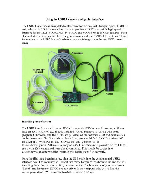
Using the <strong>USB2.0</strong> camera and guider interface<br />
The <strong>USB2.0</strong> interface is an updated replacement for the original <strong>Starlight</strong> <strong>Xpress</strong> USB1.1<br />
unit, released in 2001. Its main function is to provide a USB2 compatible high speed<br />
interface for the MX5, MX5C, MX716, MX7C and MX916 range of CCD cameras, but it<br />
also includes an interface for the <strong>SXV</strong> guide camera and for STAR2000 functions. These<br />
features make the <strong>USB2.0</strong> interface into a very useful upgrade to the non-<strong>SXV</strong> camera<br />
range.<br />
Installing the software:<br />
The USB2 interface uses the same USB drivers as the <strong>SXV</strong> series of cameras, so if you<br />
have an <strong>SXV</strong>-H9, H9C etc. already installed, you do not need to run the USB setup<br />
program. Otherwise, find the ‘USB2setup’ folder on the software CCD and double click<br />
on the ‘setup.exe’ file. Once this has been done, you should find ‘<strong>SXV</strong>IOinterface.inf’<br />
installed in C:\Windows\inf and ‘<strong>SXV</strong>IO.sys’ and ‘generic.sys’ in<br />
C:\Windows\System32\Drivers. A copy of <strong>SXV</strong>IOinterface.inf is provided on the CD for<br />
users with <strong>SXV</strong> camera software already installed. This should be copied into<br />
C:\Windows\Inf, otherwise the interface will not be identified correctly.<br />
Once the files have been installed, plug the USB cable into the computer and USB2<br />
interface box. The computer will report that ‘New hardware’ has been found and that it is<br />
installing the software required for your new device. The boot name of your interface is<br />
‘Echo3’ and it requires <strong>SXV</strong>IO.sys as a driver. If the computer asks you to find the<br />
driver, point it to C:\Windows\System32\Drivers\<strong>SXV</strong>IO.sys.
Trouble shooting the installation:<br />
The software should install automatically, but operating systems and hardware vary in<br />
their compatibility so problems can occur. Versions of Windows prior to Win98 SE and<br />
Win2000 do not support USB, so make sure that you have an up-to-date release on your<br />
machine. If you have more than one USB port, try the other ports with the interface – the<br />
hardware can make a difference. Also, adding a USB hub can induce the installation to<br />
initialise correctly. Note that although the interface will work with a USB1.1 port, it will<br />
give ‘cleaner’ and faster downloads on a <strong>USB2.0</strong> connection.<br />
Getting up and running:<br />
Once the USB installation is in place, the camera software can be copied to your working<br />
folder on the computer. Although the supplied software will give good results, other<br />
software houses are providing plug-ins for the USB2 interface. Both AstroArt and Maxim<br />
DL have support in their latest versions.<br />
Now connect the camera to the USB interface, using the 15 way cable provided. Plug in<br />
the power supply lead to the camera power block and you should be all set for an imaging<br />
session.<br />
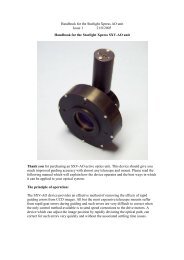
Using the add-on autoguider:<br />
A very useful accessory is the add-on autoguider head, which takes its power and control<br />
signals directly from the <strong>SXV</strong> camera, via the 18 way socket on its rear panel. The<br />
autoguider is only 1.25” in diameter and has a video style ‘CS’ mount thread in its nose,<br />
so video lenses may be attached. The guider may be used with either an off-axis prism<br />
assembly mounted in front of the <strong>SXV</strong> camera, or with a separate guide telescope, rigidly<br />
mounted alongside your imaging telescope. I personally use it with an 80mm aperture F5,<br />
inexpensive refractor as a guide ‘scope, but a shorter focal length lens will make more<br />
guide stars available in any given region of sky (See the picture below).<br />
To use the autoguider, first orient it so that the connector plug is roughly parallel to the<br />
declination axis of your mount. This is not absolutely essential, as the training routine<br />
will learn the angle of the head and compensate for it, but it is easier to understand the<br />
motion of the guide star if the guider frame is aligned with the RA and Dec axes. Now<br />
connect the head to the <strong>SXV</strong> camera, using the 18 way connector lead, including the port<br />
divider box, if it is to be used.<br />
The recommended way of connecting the autoguider output to the mount is to use an<br />
RJ11 telephone lead between the socket on the <strong>SXV</strong> camera and the autoguider input of<br />
your mount. This output is ‘active low’ (i.e. the control relays pull the guider inputs down<br />
to zero volts when applying a guide correction) and matches most of the autoguider<br />
inputs on commercial mounts. If ‘active high’ inputs are needed, or a very low control<br />
voltage drop is essential, then you will need to add a <strong>Starlight</strong> <strong>Xpress</strong> ‘relay box’ between
the guider output and the input to the mount. Please contact your local distributor if a<br />
relay box is required. Some mounts (Vixen, for example) use a similar guider input<br />
socket, but have re-arranged connections. Details are given on our web pages at the end<br />
of the ‘STAR2000’ section.<br />
To use the autoguider, please proceed as follows:<br />
1) Having started the USB2 interface software, open the autoguider control panel by<br />
clicking on the autoguider menu button.<br />
The autoguider control panel with a guide star selected<br />
2) Press the ‘Start’ button and a series of 1 second exposure guider images will begin<br />
to appear in the picture frame. If the images look too dim, use the ‘Stretch Image’<br />
slider to increase its contrast and brightness until the noise begins to be visible.<br />
3) If you haven’t focused the guider lens or ‘scope, move the mount until a bright<br />
star is visible on the guider image and then adjust the focus until it is as sharp as<br />
possible.<br />
4) At this point, you may want to test the guiding control by pressing the manual<br />
‘Move Telescope’ buttons at the bottom left corner of the control panel. You can<br />
watch the position of any stars in the guider image and confirm that they move in<br />
response to the buttons. The movement should be slow if the correct guiding rate<br />
is selected on your mount (typically 2x sidereal). Adjust this, if necessary.<br />
5) Move the mount until the required object for imaging is properly framed in the<br />
main CCD image (leave the guider menu and use the main camera control panel,<br />
as necessary).<br />
6) Re-open the guider control panel, start imaging and try to locate a clearly visible<br />
guide star. If necessary, make adjustments to the guide telescope or off-axis<br />
guider until one is found.
7) Press ‘Stop’ and then press ‘Select Guide Star’. Use the mouse to left click on the<br />
selected star and a green cross will highlight it and the co-ordinates will appear in<br />
the text boxes above the image window.<br />
8) The various guiding rate defaults, listed on the right-hand side of the control<br />
panel, are unlikely to be perfect for your particular telescope and mount. You<br />
have the option of manually selecting values, or asking the software to attempt to<br />
determine what they should be. This is done by pressing the ‘Train’ button and<br />
waiting for the software to complete a sequence of automatic moves and<br />
calculations. The training will also determine the angle at which the guide camera<br />
is oriented with respect to the RA and Dec axes. If you do not wish to train the<br />
system at this time, the default values of 6 pixels per second will serve as a<br />
starting point.<br />
9) Now press ‘Go to main camera’ and the guider control panel will be replaced by<br />
the camera control panel. Set the required exposure time for the image (say 5<br />
minutes) and press the ‘Autoguide next image’ button. The autoguider window<br />
will reappear and, after a few seconds, you should see error values appearing in<br />
the text windows at the top. The guide star will be fairly close to the green cross,<br />
although not necessarily accurately centred, and you should see the power/ guide<br />
LED on the rear of the camera brighten and change colour with each correction.<br />
10) If the star begins to drift away from the cross, despite the corrections being made,<br />
the chances are that the N/S and/or E/W directions are set wrongly. Judge which<br />
axis is incorrectly set by observing the direction of the drift and then stop the<br />
exposure by pressing ‘Esc’. Open the guider control panel and check the<br />
appropriate swap box(es). After this operation, you will probably need to find the<br />
guide star again by taking a guider image and reselecting the star, as before. Now<br />
return to the main camera menu and try the ‘Autoguide next image’ button again.<br />
11) Once guiding is taking place without problems, the main exposure can be<br />
allowed to finish and, if all is well, you should see an image with tiny circular<br />
stars.<br />
If the stars are not circular, you may need to alter the guiding parameters, or<br />
investigate the rigidity and drive performance of your mount. A lot of information can<br />
be deduced by watching the behaviour of the guide star in the guider frame. If it is<br />
continually moving between two locations, either side of the green cross, then the RA<br />
or Dec pixels per second value is set too low. The higher these values are set, the<br />
gentler the guiding becomes. Too low a value will cause an over-aggressive<br />
correction to be made and result in oscillation of the star position between two points.<br />
Another source of guiding errors can be a too accurately balanced telescope mount!<br />
Good balance can result in the telescope mount ‘bouncing’ between the gear teeth as<br />
corrections are made. A simple fix is to add a weight of about 0.5kg (1 pound) on the<br />
eastern end of the declination axis, so that there is always some pressure acting<br />
against the gear teeth.
Getting a good result from an autoguider will often entail a lot of detective work to<br />
eliminate the sources of gear error, telescope flexure, mirror shift etc., but the final<br />
result is well worth the effort!<br />
*********************************************************************<br />
Using the built-in serial ports<br />
The USB2 interface incorporates two fast serial ports for use with external accessories.<br />
The ports are available on 5 pins of the 18 way connector that is provided for the<br />
autoguider and may be accessed by plugging in a ‘serial port divider box’. The divider<br />
box and cables are available as an accessory and may be chained in series with the<br />
autoguider cable, when the guider is in use, or may be used on its own.<br />
The two serial connections are in the form of standard RS232 PC style plugs and provide<br />
TX, RX and Ground connections at RS232 levels. Access is via commands sent through<br />
the USB connection and, at the time of writing, is limited to any serial controls that are<br />
provided by the <strong>SXV</strong> software. It is expected that many more functions will be added as<br />
the software is upgraded.<br />
************************************************************<br />
Using two, or more, USB cameras on the same computer<br />
The original USB1.1 interface used an uploaded hex file (05472131.hex) to activate the<br />
camera driver. Unfortunately, the hex file was not universal and it was difficult to make<br />
the computer recognize the difference between two cameras on the same machine. This<br />
problem has been alleviated with the introduction of the USB2 interface, as the hex file is<br />
now resident in the USB hardware and has been allocated a unique VID & PID identifier.<br />
This identifier can be recognized by the software and used to distinguish between the<br />
interface and other USB devices. The interface uses a VID and PID of 12780200, the<br />
number 1278 being the official <strong>Starlight</strong> <strong>Xpress</strong> VID and 0200 the number of the device.<br />
So long as the software is written to recognize the VID and PID numbers, it can<br />
distinguish between the USB2 interface and another SX USB camera.<br />
In some few cases, two interfaces may be required to operate simultaneously on one<br />
machine (i.e. when using an MX5 to guide an MX7). In this case it is still possible for the<br />
software to identify the interfaces as different devices, as the camera firmware is not<br />
being uploaded from the computer and so there is no confusion about the identity of each<br />
camera.<br />
Terry Platt<br />
July 2004