SXV-M8C handbook.pdf - Starlight Xpress
SXV-M8C handbook.pdf - Starlight Xpress
SXV-M8C handbook.pdf - Starlight Xpress
- No tags were found...

You also want an ePaper? Increase the reach of your titles
YUMPU automatically turns print PDFs into web optimized ePapers that Google loves.
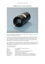
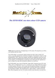
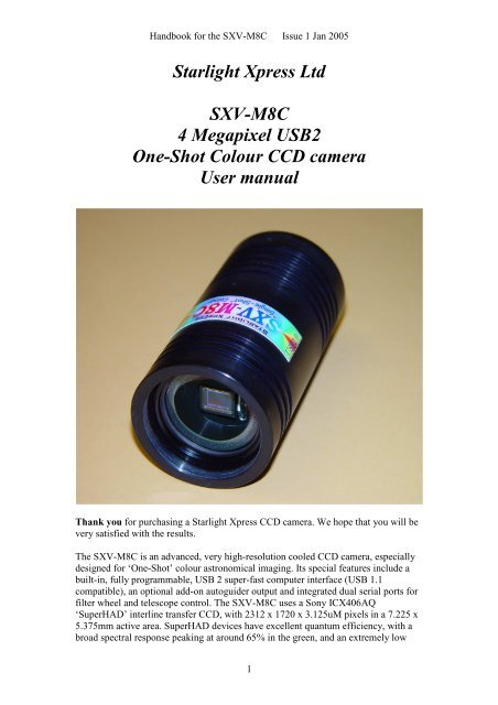
Handbook for the <strong>SXV</strong>-<strong>M8C</strong> Issue 1 Jan 2005<strong>Starlight</strong> <strong>Xpress</strong> Ltd<strong>SXV</strong>-<strong>M8C</strong>4 Megapixel USB2One-Shot Colour CCD cameraUser manualThank you for purchasing a <strong>Starlight</strong> <strong>Xpress</strong> CCD camera. We hope that you will bevery satisfied with the results.The <strong>SXV</strong>-<strong>M8C</strong> is an advanced, very high-resolution cooled CCD camera, especiallydesigned for ‘One-Shot’ colour astronomical imaging. Its special features include abuilt-in, fully programmable, USB 2 super-fast computer interface (USB 1.1compatible), an optional add-on autoguider output and integrated dual serial ports forfilter wheel and telescope control. The <strong>SXV</strong>-<strong>M8C</strong> uses a Sony ICX406AQ‘SuperHAD’ interline transfer CCD, with 2312 x 1720 x 3.125uM pixels in a 7.225 x5.375mm active area. SuperHAD devices have excellent quantum efficiency, with abroad spectral response peaking at around 65% in the green, and an extremely low1
Handbook for the <strong>SXV</strong>-<strong>M8C</strong> Issue 1 Jan 2005dark current, well below that of any comparable CCD currently available. TheICX406AQ incorporates a ‘Bayer Matrix’ of Red, Green and Blue filters, depositeddirectly onto the CCD pixels and a downloaded image may be quickly converted intoa full-colour picture by application of the software provided.The full-frame download time is approximately 14 seconds and binned 4x4downloads take only 3 seconds, so finding and centring are very quick and easy in thismode. If you have only a USB 1.1 connection on your computer, the download time islonger, but is still reasonable at around 25 seconds for a full resolution frame.Please take a few minutes to study the contents of this manual, which will help you toget the camera into operation quickly and without problems. I am sure that you wantto see some results as soon as possible, so please move on to the ‘Quick Start’ section,which follows. A more detailed description of imaging techniques will be found in alater part of this manual.‘Quick Starting’ your <strong>SXV</strong>-<strong>M8C</strong> systemIn the shipping container you will find the following items:1) The <strong>SXV</strong>-<strong>M8C</strong> camera head.2) A power supply module.3) A USB camera cable.4) A guider cable5) An adaptor for 1.25” drawtubes.6) An adaptor for 2” drawtubes and M42 Pentax thread lenses.7) A disk with the <strong>SXV</strong>-<strong>M8C</strong> control software and this manual.Optional extra items include:1) A serial port adaptor and cable.2) An add-on guide camera head (includes a cable).You will also need a PC computer with Windows 98, Windows Me, Windows 2000or Windows XP installed (NOT Windows 95 or NT4). This machine must have atleast one USB port available and at least 32 Megs of memory. If you intend to viewthe finished images on its screen, then you will also need a graphics card capable ofdisplaying an image with a minimum of 1024 x 768 pixels in 24 bit colour. A mediumspecification Pentium with between 1000 and 3000MHz processor speed issatisfactory. USB 2 PCI cards are readily available for upgrading a USB 1.1 machine,if you want to achieve the best possible performance. Please note that USB 2.0operates at a very high speed and cannot operate over very long cables. Five metres ofgood quality cable is the maximum normally possible. Adding one, or more, USB 2‘Hubs’ in line can extend this, if necessary.Installing the USB system:First, find a free USB socket on your PC and plug in the USB cable. If you do nothave a USB capable computer, it is normally possible to install a USB 2 card into an2
Handbook for the <strong>SXV</strong>-<strong>M8C</strong> Issue 1 Jan 2005expansion slot. Almost all machines manufactured after 1996 provide a pair of USB1.1 sockets on the rear panel and either of these may be used if USB 1.1 issatisfactory. Please note that it may be necessary to enable your USB system in thecomputer BIOS (the SETUP menu which can usually be accessed at start-up). ManyBIOS systems have the ability to disable ‘Plug and Play’ devices, such as the USBports, so please make sure that these are enabled.The next operation is to run the USB installer from the CD ROM provided. Insert theCD into the computer and run the ‘Install<strong>SXV</strong>’ file which is found in the <strong>SXV</strong>-<strong>M8C</strong>directory. This will install the following files:1) ‘<strong>SXV</strong>IO_BlockIO_<strong>M8C</strong>.inf’ in C:\Windows\Inf\2) ‘Generic.sys and ‘<strong>SXV</strong>IO.sys’ in C:\Windows\System32\Drivers\If you cannot see the directories ‘C:\Windows\Inf’ and ‘Windows\System32\Drivers’,this will be due to the setup of your Windows Explorer software. In this case, go tothe ‘Tools’ menu, followed by ‘Folder Options’ and select ‘View’. Now select ‘Showhidden files and folders’ and make sure that the ‘Hide file extensions for known filetypes’ and ‘Hide protected operating system files’ check boxes are NOT checked.After this, the various directories and files should be visible.It is now time to set up the USB device. Plug the USB cable into the camera andobserve the computer screen. After a brief delay, you should see an information box,which reports that the computer is ‘Installing a <strong>Starlight</strong> <strong>Xpress</strong> CCD camera’. If all iswell, the cycle will complete within a couple of seconds, but it is possible that youmay have to prompt the system with the location of the <strong>SXV</strong>IO.sys file(Windows\System32\Drivers). After another brief delay, the computer should say thatit has found a new USB2.0 device and is installing a ‘<strong>Starlight</strong> <strong>Xpress</strong> USB 2.0 <strong>SXV</strong>-<strong>M8C</strong> CCD camera’. In some cases the installation will halt after the first stage andyou will need to restart the machine, or unplug and re-plug the USB lead to initiatethe second step.3
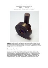
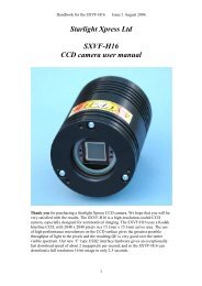
Handbook for the <strong>SXV</strong>-<strong>M8C</strong> Issue 1 Jan 2005At the end of this process, the USB interface will be installed as an ‘<strong>SXV</strong>IOClassdevice’ and the camera software will be able to access it. You can confirm that theinstallation is complete by checking the status of the USB devices in the Windows‘Device Manager’ (see above). Start up the Windows ‘Control Panel’ and select‘System’. Now click on the tab labelled ‘Device Manager’ and all of the systemdevices will be displayed in a list (see above). If the installation is successful, therewill be a diamond shaped symbol labelled ‘<strong>SXV</strong>IOClass’ and clicking on the ‘+’ signwill reveal it to be a ‘<strong>Starlight</strong> <strong>Xpress</strong> USB 2.0 camera driver’. If this device is faulty,try clicking on it and selecting ‘properties’ and then ‘update driver’. Following the onscreen instructions will allow you to re-select the correct inf file (<strong>SXV</strong>IO.inf) anddriver file (<strong>SXV</strong>IO.sys), which should fix the problem.Adding the camera control software:Now that the USB system is installed, the camera control program can be used tooperate your <strong>SXV</strong>-<strong>M8C</strong>. Copy the camera software files from the CD and paste theminto a suitable directory, such as ‘<strong>SXV</strong>H9’ on your computer’s C: drive. Yourdirectory should contain the files <strong>SXV</strong>_H9C.exe, <strong>SXV</strong>_H9C.hlp, bwcc32.dll andwsc32.dllConnecting the camera:The camera rear panel4
Handbook for the <strong>SXV</strong>-<strong>M8C</strong> Issue 1 Jan 2005Connect up the power supply and switch it on. You can start the ‘<strong>SXV</strong>_<strong>M8C</strong>’software by double clicking on the icon and you should see the main menu and imagepanel appear. If the USB connection is OK, a message box will inform you of the‘Handle’ number for the <strong>SXV</strong>IO interface and various other version details etc. Themain program window will now be seen.If you press the ‘Camera’ button at the top left, the program will warn you that the‘Program Defaults’ have not been set, but pressing ‘OK’ will allow you to continue.The camera default settings are not important for current purposes and may be left asthe software start-up values for now, but the warning message may be removed byselecting ‘Set program defaults’ from the ‘File’ menu and then saving the defaultswindow by pressing the ‘Save changes’ button. Once the camera control panel is seen,you are all set to take your first images!Recording your first image:We now have the camera and computer set up to take pictures, but an optical systemis needed to project an image onto the CCD surface. You could use your telescope,but this introduces additional complications, which are best avoided at this earlystage. There are two simple options, at least one of which is available to everyone:1) Attach a standard ‘M42’ SLR camera lens to the <strong>SXV</strong>-<strong>M8C</strong>, using the 25mmspacer to achieve the correct focal distance.5
Handbook for the <strong>SXV</strong>-<strong>M8C</strong> Issue 1 Jan 2005Or2) Create a ‘Pin hole’ lens by sticking a sheet of aluminium baking foil over the endof the 1.25” adaptor and pricking its centre with a small pin.If you use a normal lens, then stop it down to the smallest aperture number possible(usually F22) as this will minimise focus problems and keep the light level reasonablefor daytime testing. The pin hole needs no such adjustments and will workimmediately, although somewhat fuzzily.Point the camera + lens or pinhole towards a well-lit and clearly defined object somedistance away. Now enter the ‘File’ menu in the <strong>SXV</strong>_<strong>M8C</strong> software and click on‘<strong>SXV</strong>-<strong>M8C</strong> camera interface’ (or use the camera icon). Select an exposure time of 0.1seconds, High Resolution Interlaced mode and press ‘Take Photo’.6
Handbook for the <strong>SXV</strong>-<strong>M8C</strong> Issue 1 Jan 2005After the exposure and download have completed (about 14 seconds) an image ofsome kind will appear on the computer monitor. It will probably be poorly focusedand incorrectly exposed, but any sort of image is better than none! In the case of thepinhole, all that you can experiment with is the exposure time, but a camera lens canbe adjusted for good focus and so you might want to try this to judge the high imagequality that it is possible to achieve. With our adaptor, most lenses come to infinityfocus at about midway through their normal focus adjustment range.Various other exposure options are available, as can be seen in the picture above. Forexample, you can ‘Bin’ the download 2x2, or more, to achieve greater sensitivity andfaster download, or enable ‘Continuous mode’ to see a steady stream of images. Thereason for the two ‘High Resolution’ modes (Progressive or Interlaced) is to enableboth short and long exposures to be made in a format that can be colour converted.Progressive mode is ideal for use with relatively long ‘deep sky’ images (more thanabout 10 seconds), but will not work well for shorter exposures (daylight orplanetary). Planetary shots are made in ‘Interlaced’ mode.‘Focus mode’ downloads a 128 x 128 segment of the image at high speed. The initialposition of the segment is central to the frame, but can be moved by selecting ‘Focusframe centre’ in the ‘File’ menu and clicking the desired point with the mouse. Thefocus window has an adjustable ‘contrast stretch’, controlled by the 12-16 bit slider.The image will be ‘normal’ if 16 bits is selected, while setting lower values willincrease the image brightness in inverse proportion. Please note that ONLY 1x1binned images will decode to colour – the other modes are for focusing andacquisition only.If you cannot record any kind of image, please check the following points:7
Handbook for the <strong>SXV</strong>-<strong>M8C</strong> Issue 1 Jan 20051) Ensure that the power indicator lamp is on and that the cables are properly homein their sockets.2) If the screen is completely white, the camera may be greatly overexposed. Try ashorter exposure time, or stop down your lens. See if covering the lens causes theimage to darken.3) If the USB did not initialise properly, the camera start-up screen will tell you thatthe connection is defective. Try switching off the power supply and unplugging theUSB cable. Now turn the power supply on and plug in the USB cable. This will reloadthe USB software and may fix the problem after restarting the <strong>SXV</strong>_H9Cprogram. Otherwise, check the device driver status, as previously described, andre-install any drivers which appear to be defective.4) If you cannot find any way of making the camera work, please try using it withanother computer. This will confirm that the camera is OK, or faulty, and you canthen decide how to proceed. Our guarantee ensures that any electrical faults arecorrected quickly and at no cost to the customer.Converting your image to colour:Once you have a recognisable image, it is quite easy to convert it to full colour. The‘raw’ image will appear to have a fine grid distributed across it – this is the colourfilter matrix and the variations of pixel brightness encode the colour data which wewant to extract. Here is an enlarged section of a raw image:Click on ‘Colour Synthesis’ in the main menu and you will see the synthesiser dialog.8
Handbook for the <strong>SXV</strong>-<strong>M8C</strong> Issue 1 Jan 2005This includes various options for correcting the colour synthesis for variations in thelighting conditions, filters etc. Briefly, these items perform the following functions:1) Daylight Image? – If an unfiltered lens is used, the infra-red content of thelight will tend to produce a Green – Blue shift in the balance. A partialcorrection of this bias is provided by selecting this option, but the best optionis to use an infra-red blocking filter when taking daylight shots (see 5 below).2) Light Pollution Correction: - This option is for deep sky colour images,where a strong colour bias is often present in the sky background. This optionattempts to return the background colour to a neutral grey.3) Colour Smoothing Filter: - Applies a low pass filter to the colour data tosmooth out colour noise.4) Apply Anti-Alias: - Runs a special filter over the colour data to removecoloured artefacts around sharp edges. This is especially useful for cleaning uperratically coloured star images.5) IR Filter Used? – Sets the colour balance to allow for the loss of infra-redcontent when using an IR blocking filter.6) Stretching: - A selection of contrast boosting options which are preset forvarious subjects.7) Remove Background: - This option will adjust the sky background brightnessto give an optimum background level.9
Handbook for the <strong>SXV</strong>-<strong>M8C</strong> Issue 1 Jan 20058) High Pass filters: - Automatically sharpen the luminance data to emphasisefine details. Most useful for sharpening planetary images but will also increasethe noise content.For your first test images, I suggest that you turn on the Anti-Alias option andpossibly the ‘Daylight Image’ option.Now press the ‘Create Image’ button. After a couple of seconds, your raw monoimage will be replaced by a full colour version.There is every reason to expect that the image will be reasonably well colourbalanced, but if it is not, you can adjust the colour in the ‘Set Colour Balance’ dialogbox (Under ‘Colour’ in the main menu).10
Handbook for the <strong>SXV</strong>-<strong>M8C</strong> Issue 1 Jan 2005The colour balance controls seem complex, but are really quite easy to use. The mostuseful controls are the ‘Start’ and ‘Saturation Factor’ settings. Saturation factor willsimply vary the colour intensity, without any alteration of the colour balance, but the‘Start’ settings for each colour will alter the colour rendering of the dimmer parts ofthe image. As most astronomical images are badly affected by light pollution, whichaffects the dimmer background colours in particular, the start point settings areparticularly helpful for correcting this. If you move the start point of the Redhistogram a few points to the right and click on ‘Apply’, the new image will haveLESS red in the background and will appear more Cyan. Similarly, if you move theGreen start point to the right, the image will appear more Magenta and moving theblue start point will turn it more Yellow. Do not move the start points beyond the startof the main burst of histogram data, or you will introduce colour errors into lowsaturation parts of the image. Just move the sliders by small amounts in the clear areabelow the main peak, until the background is nicely balanced.In some cases, the histograms may all start a long way above zero (usually in astro.images with a lot of light pollution). In this case, slide the start point settings for allcolours until they are equally distant from the beginning of the colour data, but quiteclose to it. This will both correct the colour balance (apart from any fine tweaks) andincrease the colour saturation.In some images, the colour data may be balanced differently in the highlights andshadows. For example, the dark areas may be quite neutral in colour, but thehighlights may be bluish in tint. This indicates a ‘slope error’ in one or more coloursand, in this example it is caused by the blue data increasing too quickly whencompared with the red and green data. To correct for this, the other histogram slidersmay be used as slope adjusters. In the case of the excess blue, try increasing the topend (Max) value to greater than 255 (300 max is allowed). This will reduce the blueslope and result in a more yellowish rendition.Other image enhancements:Your first image may be satisfactory, but it is unlikely to be as clear and sharp as itcould be. Improved focusing and exposure selection may correct these shortcomings,and you may like to try them before applying any image enhancement with the11
Handbook for the <strong>SXV</strong>-<strong>M8C</strong> Issue 1 Jan 2005software. However, there will come a point when you say, “That’s the best that I canget” and you will want to experiment with the effects of image processing. In the caseof daylight images, the processing options are many, but there are few that willimprove the picture in a useful way. The most useful of these are the ‘NormalContrast Stretch’ and the ‘High Pass Low Power’ filter. The high pass filter gives amoderate improvement in the image sharpness, and this can be very effective ondaylight images.Too much high pass filtering results in dark borders around well-defined features andwill increase the noise in an image to unacceptable levels, but the Low Power filter isclose to optimum and gives a nicely sharpened picture, as above.The ‘Contrast’ routines are used to brighten (or dull) the image highlights andshadows. A ‘Normal’ stretch is a simple linear operation, where two pointers (the‘black’ and ‘white’ limits) can be set at either side of the image histogram and used todefine new start and end points. The image data is then mathematically modified sothat any pixels that are to the left of the ‘black’ pointer are set to black and any pixelsto the right of the ‘white’ pointer are set to white. The pixels with values between thepointers are modified to fit the new brightness distribution. Try experimenting withthe pointer positions until the image has a pleasing brightness and ‘crispness’. Mostdaylight pictures suffer from having too much ‘Gamma’ (a way of referring to thecontrast response curve) and look unnaturally contrasty. Applying a ‘Power law’stretch of about 0.5 power will often make them look better.At this point, you will have a working knowledge of how to take and process an <strong>SXV</strong>-<strong>M8C</strong> image. It is time to move on to astronomical imaging, which has its own,unique, set of problems!*********************************************************************Astronomical Imaging with the <strong>SXV</strong>-<strong>M8C</strong>1) Getting the image onto the CCD:It is fairly easy to find the correct focus setting for the camera when using a standardSLR lens, but quite a different matter when the <strong>SXV</strong>-<strong>M8C</strong> is attached to a telescope!The problem is that most telescopes have a large range of focus adjustment and theCCD needs to be quite close to the correct position before you can discern details wellenough to optimise the focus setting. An additional complication is the need to addvarious accessories between the camera and telescope in order that the image scale issuitable for the subject being imaged and (sometimes) to include a ‘flip mirror’ finderunit for visual object location.A simple, but invaluable device is the ‘par-focal eyepiece’. This is an eyepiece inwhich the field stop is located at the same distance from the barrel end, as the CCD isfrom the camera barrel end.12
Handbook for the <strong>SXV</strong>-<strong>M8C</strong> Issue 1 Jan 2005In this case, the camera and eyepiece are made par-focal with each other by lockingup the mirror, focusing the camera on an easy object, such as a moderately bright starand then flipping the mirror down to view the same star with the eyepiece. Once theeyepiece has been locked into the correct position, you can use it to focus on theimage by lowering the flip mirror and operating the telescope focus wheel until theimage is sharp. When the mirror is raised, the image will fall onto the CCD surfaceand should be accurately in focus. Most flip mirror units allow several adjustments tobe made, so that the image can be centred properly in the eyepiece and CCD fields,which are not necessarily coincident when you first buy your unit!Opinions vary as to the utility of flip mirrors. They are a convenient way to find andfocus, but they add quite a bit of extra length between the camera and telescope. Thiscan be very inconvenient with Newtonians, and not a lot better with SCTs, especiallyif the assembly is somewhat flexible. They also make it difficult to use a focal reducerwith your camera, as the rapidly converging light cone from a reducer cannot reach allthe way through the flip mirror unit to the CCD surface. If you are using one of thepopular F3.3 compressors for deep sky imaging, you will NOT be able to include aflip mirror unit in front of your camera and using a par-focal eyepiece is your bestoption.Whichever device you use, it is necessary to set up a good optical match between yourcamera and the telescope. Most SCTs have a focal ratio of around F10, which is toohigh for most deep sky objects and too low for the planets! This problem is quite easyto overcome, if you have access to a focal reducer (for deep sky) and a Barlow lensfor planetary work. The Meade F3.3 focal reducer is very useful for CCD imaging andI can recommend it from personal experience. It does not require a yellow filter foraberration correction, unlike some other designs, so it can also be used for tri-colour14
Handbook for the <strong>SXV</strong>-<strong>M8C</strong> Issue 1 Jan 2005imaging. If you use a focal reducer, do not try to use it at maximum reduction, as thelarge chip of the <strong>SXV</strong>-<strong>M8C</strong> will suffer from considerable ‘vignetting’ (dimmingtowards the corners) and this will be difficult to remove from your images. To achievethis, use only a short extension tube between the focal reducer lens and the camera.The longer the extension tube used, the greater the focal reduction will be. As a guide,most CCD astronomers try to maintain an image scale of about 2 arc seconds perpixel for deep sky images. This matches the telescope resolution to the CCDresolution and avoids ‘undersampling’ the image, which can result in square stars andother unwanted effects. To calculate the focal length required for this condition toexist, you can use the following simple equation:F = Pixel size * 205920 / Resolution (in arc seconds)In the case of the <strong>SXV</strong>-<strong>M8C</strong> and a 2 arc seconds per pixel resolution, we getF = 0.00313 * 205920 / 2= 324mmFor a 200mm SCT, this is an F ratio of 324 / 200 = F1.6, which is only possible withsomething like the ‘Fastar’ adaptor. Hence images with normal SCT optics are goingto be considerably ‘oversampled’. This can often be acceptable, but it is clear that the<strong>SXV</strong>-<strong>M8C</strong> is better suited to small refractors and lenses than long focus SCTtelescopes.The same equation can be used to calculate the amplification required for goodplanetary images. However, in this case, the shorter exposures allow us to assume amuch better telescope resolution and 0.25 arc seconds per pixel is a good value to use.The calculation now gives the following result:F = 0.00313 * 205920 / 0.25 = 2578mmThis is approximately F13 when used with a 200mm SCT and so we could use thenative F10 focal length with good results. A Barlow lens can be used to increase theimage scale, if necessary.Achieving a good focus:Your starting point will depend on the focus aids, if any, which you are using. Withthe par-focal eyepiece, you should slip the eyepiece into the drawtube and focusvisually on a moderately bright star (about 3 rd magnitude). Now withdraw theeyepiece and carefully insert the camera nosepiece, until it is bottomed against thedrawtube end, and then lock it in place.With the flip mirror unit, all that is needed is to swing the mirror down and adjust thefocus until the star is sharply defined and centred in the viewing eyepiece. Now liftthe mirror and you are ready to start imaging.<strong>SXV</strong>_<strong>M8C</strong> has a focus routine that will repeatedly download and display a 128 x 128pixel segment of the image at relatively high speed. This focus window may bepositioned anywhere in the camera field and can be displayed with an adjustabledegree of automatic contrast stretching (for focusing on faint stars). To use this mode,15
Handbook for the <strong>SXV</strong>-<strong>M8C</strong> Issue 1 Jan 2005start up the software and select the <strong>SXV</strong> camera interface (File menu). Set the cameramode to Binned 1x1 and select an exposure time of 1 second. Press ‘Take Picture’ andwait for the image to download. There is a good chance that your selected star willappear somewhere within the image frame and it should be close to a sharp focus. Ifthe focus is still poor, then it may appear as a pale disk of light, often with a darkcentre (the secondary mirror shadow in an SCT, or Newtonian). Now select the ‘File’menu again and click on ‘Focus frame centre’; you can now use the mouse pointer toclick on the star image and the new focus frame co-ordinates will be displayed. Nowreturn to the camera interface window and click on ‘Start’ in the Focus frame. Thecomputer will now display a continuous series of 128 x 128 pixel images in the focuswindow and you should see your selected star appear somewhere close to the centre.A ‘peak value’ (the value of the brightest pixel) will also be shown in the adjacent textbox and this can be used as an indication of the focus accuracy. Although the peakvalue is sensitive to vibration and seeing, it tends towards a maximum as the focus isoptimised. Carefully adjust the focus control on your telescope until the image is assharp as possible and the peak value reaches a maximum. Wait for any vibration todie down before accepting the reading as reliable and watch out for bursts of badseeing, which reduce the apparent focus quality. Quite often, the peak value willincrease to the point where it is ‘off scale’ at 4095 and in this case you must halt thefocus sequence and select a shorter exposure if you wish to use the peak value as anindicator. Once you are happy with the focus quality achieved, you might like to trimthe settings of your par-focal or flip mirror eyepiece to match the current cameraposition.Although you can reach a good focus by the above method, many observers prefer touse additional aids, such as Hartmann masks (an objective cover with two or threespaced holes) or diffraction bars (narrow parallel rods across the telescope aperture).These make the point of precise focus easier to determine by creating ‘double images’or bright diffraction spikes around stars, which merge at the setting of exact focus.The 12-16 bit slider control allows you to adjust the contrast of the focus frame forbest visibility of the star image. It defaults to maximum stretch (12 bits), which isgenerally ideal for stars, but a lower stretch value is better for focusing on planets.Taking your first astronomical image:I will assume that you are now set up with a focused camera attached to a telescopewith an operating sidereal drive. If so, you are now in a position to take a moderatelylong exposure of some interesting deep-sky astronomical object (I will deal withplanets later). As most drives are not very accurate beyond a minute or two ofexposure time, I suggest that you find a fairly bright object to image, such as M42,M13, M27 or M57. There are many others to choose from, but these are goodexamples.Use the finder to align on your chosen object and then centre accurately by using thefocus frame and a short exposure of between 1 and 5 seconds. The ’12-16 bit’ sliderin the focus frame allows you to adjust the image contrast if you find that the object istoo faint with a short exposure. Once properly centred and focused, take an exposureof about 60 seconds in ‘Progressive’ mode, and observe the result. Initially, the imagemay appear rather barren and show only a few stars, however, there is a great deal ofdata hidden from view. You can get to see a lot of this, without affecting the imagedata, if you go to the ‘View’ menu and select ‘Auto Contrast Stretch Image’. The faint16
Handbook for the <strong>SXV</strong>-<strong>M8C</strong> Issue 1 Jan 2005image data will then appear in considerable detail and I think that you will beimpressed by the result!If you are happy with the image, go to the ‘File’ menu and save it as a FIT file in aconvenient directory.Most competitive brands of CCD camera require a ‘dark frame’ to be subtracted fromyour images to achieve the best results. A dark frame is simply a picture which wastaken with the same exposure as your ‘light frame’, but with the telescope objectivecovered, so that no light can enter. It records only the ‘hot pixels’ and thermalgradients of your CCD, so that these defects are largely removed when the dark frameis subtracted from the light frame. The <strong>SXV</strong>-<strong>M8C</strong> CCD is quite different from thoseused in other brands of camera and generates an extremely low level of dark noise.Indeed, it is so low that subtracting a dark frame can actually INCREASE the noise inyour images! This is because the statistical noise of the dark frame can exceed the‘pattern noise’ from warm pixels and hence add to that of the subtracted result. If yourtest pictures have an exposure time of less than about 10 minutes (as above), thendon’t bother with a dark frame, just ‘kill’ any hot pixels with your processingsoftware. In <strong>SXV</strong>-<strong>M8C</strong>, the ‘Median filter’ can do this, but other software (e.g.Maxim DL) will provide a ‘hot pixel killer’ that can be mapped to specific locationsin the image.If you feel that dark frame really is necessary, please proceed as follows:To take a dark frame, just cover the telescope objective with the lens cap, or drop theflip mirror to block the light path to the CCD (make sure that this is light tight), andtake another exposure of the same length as that of the light frame. This image will bea picture of the dark signal generated during your exposure and it should be savedwith your image for use in processing the picture. If many such darks are recordedand averaged together, the statistical noise will be reduced, but the gains to be had arerather small compared with the effort involved.As variations in ambient temperature will affect the dark signal, it is best to take thedark frames within a few minutes of capturing your images. For the same reason, it isnot wise to use ‘old’ dark frames if you want the best possible results, however, somesoftware allows you to scale library dark frames to match the image (e.g. AstroArt)and this can be useful as a time saver.‘Flat fields’ are often recommended for optimising the results from your CCDcamera, but these are generally less important than dark frames, especially if youmake sure that the optical window of the camera is kept dust-free. The purpose of aflat field is to compensate for uneven illumination and sensitivity of the CCD and it isbetter to avoid the need for one by keeping the optics clean and unvignetted. I willignore flat fielding for current purposes and describe the process in detail at a laterstage.Processing a deep-sky image:The following instructions include the subtraction of a dark frame, but this may beregarded as optional.17
Handbook for the <strong>SXV</strong>-<strong>M8C</strong> Issue 1 Jan 20051) Make sure the ‘Auto Contrast Stretch’ is switched off and load your image into the<strong>SXV</strong>_<strong>M8C</strong> program. Select ‘Merge’ and then ‘Subtract Dark Frame’. Pick theappropriate dark frame and the software will then remove the dark signal from yourimage, leaving it somewhat darker and slightly smoother than before.2) The next step is to process the image into colour, but you may find that theapplication of a gentle contrast stretch to the image before synthesis will improve thecolour result. Don’t overdo the stretch, as the colour range can then exceed thedynamic range available, leading to uncorrectable colour errors. Make sure that youkeep a copy of the original file – just in case! Set the colour synthesiser to apply theanti-alias filter and then run it.3) The resulting image will probably still look faint and dull, with a pale orange orgreen background due to light pollution. Try using the ‘Start point’ adjustment in theColour balance menu to get something close to a neutral background colour. Movingup the red and green start points will reduce the light pollution tint in the background.It is now time to process the ‘luminance’ (brightness and contrast) of the image to getthe best visual appearance. First, use the ‘Normal’ contrast stretch to darken thebackground by setting the ‘Black’ slider just below the main peak of the histogram.Alternatively, you can use the ‘Remove Background’ option to let the software decideon the best setting. This will greatly reduce the background brightness and the imagewill begin to look rather more attractive, if dark. You can now try brightening thehighlights with another ‘Normal’ stretch, in which you bring down the ‘White’ sliderto just above the main image peak. The best setting for this is rather more difficult toguess and you may need several attempts before the result is ideal. Just use the ‘Undolast filter’ function, if necessary, to correct a mistake. In many cases, a ‘Normal’contrast stretch will give a good result, but may ‘burn out’ the bright regions andleave the faint parts of the image rather lacking in brightness. To combat this, many18
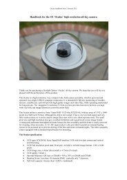
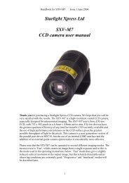
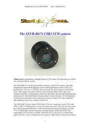
Handbook for the <strong>SXV</strong>-<strong>M8C</strong> Issue 1 Jan 2005imagers will use a combination of ‘Normal’ and ‘Non-linear’ contrast stretches. Thebest settings are different for different objects, but performing a non-linear or powerlaw stretch, followed by normalising the background to black with a normal stretch, isthe usual procedure.5) The image will now look quite impressive and I hope that you are pleased withyour first efforts!M27 from a 15 minute exposure at F5 with a C11Further small refinements are usually possible and you will become expert at judgingthe best way to achieve these as your experience increases. As a rough guide, the‘Filters’ menu can be used to sharpen, soften or noise reduce the image. Strong ‘HighPass’ filters are usually not a good idea with deep sky images, as the noise will bestrongly increased and dark rings will appear around the stars, but a ‘Median’ filtercan remove odd speckles (hot pixels) and a mild ‘Unsharp Mask’ (Radius 3, Power 1)will sharpen without too much increase in noise.Other things to try include summing several images for a better signal to noise ratio.This MUST be done AFTER colour synthesis, as summing raw images is highlylikely to destroy the filter grid pattern and so prevent the creation of a proper colourimage. Summing can be done in the ‘Merge’ menu and involves loading the firstprocessed image, selecting a reference point (a star) then loading the second imageand finding the same star with the mouse. Once the reference is selected, you caneither add directly, or average the images together. Averaging is generally better, asyou are less likely to saturate the highlights of the picture. The signal-to-noise ratiowill improve at a rate proportional to the square root of the number of summations19
Handbook for the <strong>SXV</strong>-<strong>M8C</strong> Issue 1 Jan 2005(summing 4 images will double the signal-to-noise), but different exposures must beused. Summing an image with itself will not change the S/N ratio!Although I have concentrated on the use of a telescope for deep-sky imaging, do notforget that you have the option of using an ordinary camera lens for impressive widefieldshots! A good quality 135 or 200mm F3.5 lens with an infrared blocking filterand a ‘minus violet’ filter will yield very nice images of large objects, such as M31,M42, M45 etc. If you cannot obtain a large IR blocker for the front of the lens, it isquite acceptable to place a small one behind the lens, inside the adaptor tube. You canalso try using a light pollution filter to bring out nebulae, reduce light pollution andsharpen the star images. The Hutech/IDAS P2 type is particularly effective with acolour camera.Taking pictures of the planets:Planetary imaging is in many ways quite different from deep sky imaging. Most deepsky objects are faint and relatively large, so a short focal length and a long exposureare needed, while planets are bright and very small, needing long focal lengths andshort exposures. High resolution is critical to achieving good results and I havealready shown how a suitable focal length can be calculated and produced, ifnecessary, by using a Barlow lens. Planetary images are taken in High ResolutionInterlaced mode.Many camera users comment on the difficulty of finding the correct focus whentaking pictures of Jupiter etc. This is usually due to poor seeing conditions, which areonly too common, but may also be due in part to poor collimation of your telescope.Please ensure that the optics are properly aligned as shown by star testing, or by usingone of the patent collimation aids that are widely available. It is also better to use astar for initial focusing, as planetary detail is difficult to judge in bad seeing. Althoughthe star will also suffer from blurring, the eye can more easily judge when the mostcompact blur has been achieved!You could begin by imaging lunar craters, or the planets, Jupiter, Saturn or Mars. Therapid variations of seeing which accompany planetary imaging will ruin the definitionof about 95% of your images and so I recommend setting the camera to run in‘Autosave’ mode. This will automatically take a sequence of images and save themwith sequential file names in your ‘Autosave’ directory. Dozens of images will besaved, but only one or two will be satisfactory for further processing. The ‘Subframe’mode of the <strong>SXV</strong> may be found useful for limiting the wasted area and reducing thedownload time of small planetary images.To start the Autosave process, call up the <strong>SXV</strong> Camera Interface and select the‘Continuous Mode’ check box at the top (make sure the rest are unchecked). Nowcheck the ‘Autosave Image’ checkbox near the bottom of the window. If you nowclick on ‘Take Picture’ the automatic sequence will begin and will not stop until youpress a computer key. The images will be saved in FITs format with sequential namessuch as ‘Img23, Img24….’ and will be found in the ‘Autosave’ directory (or a subdirectoryof Autosave, set up in the program defaults menu).20
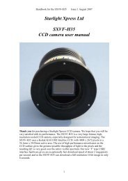
Handbook for the <strong>SXV</strong>-<strong>M8C</strong> Issue 1 Jan 2005The exposure time needed for good planetary images is such that the image histogramhas a peak value at around 200 and does not extend much above 220 (Ignore themajor peak near zero, due to the dark background). If you use too short an exposuretime, the image noise level will be increased, and if too long a time is used you willsaturate the highlights and cause white patches on the image. With the recommendedfocal length, Jupiter and Mars will both need an exposure time of between 0.1 and 1seconds and Saturn will need between 0.5 and 2 seconds.Processing a planetary image:Planetary images have one major advantage over deep sky images, when you come toprocess them – they are MUCH brighter, with a correspondingly better signal to noiseratio. This means that aggressive sharpening filters may be used without making theresult look very noisy and so some of the effects of poor seeing can be neutralised.Try applying an ‘Unsharp Mask’ filter with a radius of 5 and a power of 5. This willgreatly increase the visibility of any detail on the planet, but the optimum radius andpower will have to be determined by experiment.Jupiter after an ‘Unsharp mask’In general terms, the larger the image and the worse the seeing, then the wider theradius for best results. My Jupiter shots are usually about one third the height of theCCD frame and I find that the ‘radius 5, power 5’ values are good for most averageseeing conditions. If you have exceptionally good conditions, then a reduction to R=3,P=3 will probably give a more natural look to the image, as too large a radius andpower tends to outline edges with dark or bright borders.As a finishing touch, the application of a Median filter or a Weighted Mean Low Passfilter can be useful to smooth out the high frequency noise after a strong UnsharpMask.As with deep-sky images, it is advantageous to sum colour planetary images togetherto improve the signal to noise ratio. In this case, the ‘averaging’ option should alwaysbe used, or the result is likely to exceed the dynamic range of the software andsaturate the highlights. Aligning the images is always something of a problem, as21
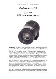
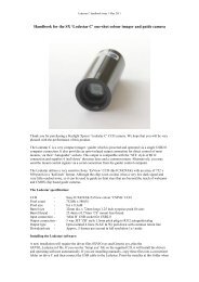
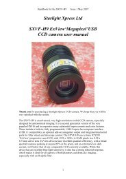
Handbook for the <strong>SXV</strong>-<strong>M8C</strong> Issue 1 Jan 2005there are rarely any stars to use when imaging the planets, but Jupiter’s satellites canbe useful reference points. Otherwise, you will have to find a well-defined feature onthe planet, or estimate where the centre of the disk is located. Some moresophisticated software can automatically align planetary images and you may findthese programs to be very useful.*********************************************************************Using the add-on autoguider:A very useful accessory is the add-on autoguider head, which takes its power andcontrol signals directly from the <strong>SXV</strong> camera, via the 18 way socket on its rear panel.The autoguider is only 1.25” in diameter and has a video style ‘CS’ mount thread inits nose, so video lenses may be attached. The guider may be used with either an offaxisprism assembly mounted in front of the <strong>SXV</strong> camera, or with a separate guidetelescope, rigidly mounted alongside your imaging telescope. I personally use it witha 70mm aperture, F12, inexpensive refractor as a guide ‘scope, but a shorter focallength lens will make more guide stars available in any given region of sky (See thepicture below).To use the autoguider, first orient it so that the connector plug is roughly parallel tothe declination axis of your mount. This is not absolutely essential, as the trainingroutine will learn the angle of the head and compensate for it, but it is easier tounderstand the motion of the guide star if the guider frame is aligned with the RA andDec axes. Now connect the head to the <strong>SXV</strong> camera, using the 18 way connector lead,including the port divider box, if it is to be used.The recommended way of connecting the autoguider output to the mount is to use anRJ11 telephone lead between the socket on the <strong>SXV</strong> camera and the autoguider inputof your mount. This output is ‘active low’ (i.e. the control relays pull the guider inputsdown to zero volts when applying a guide correction) and matches most of theautoguider inputs on commercial mounts. If ‘active high’ inputs are needed, or a verylow control voltage drop is essential, then you will need to add a <strong>Starlight</strong> <strong>Xpress</strong>‘relay box’ between the guider output and the input to the mount. Please contact yourlocal distributor if a relay box is required. Some mounts (Vixen, for example) use asimilar guider input socket, but have re-arranged connections. Details are given on ourweb pages at the end of the ‘STAR2000’ section.22
Handbook for the <strong>SXV</strong>-<strong>M8C</strong> Issue 1 Jan 2005The autoguider installed on a 70mm refractor guide ‘scope in the author’s garden23
Handbook for the <strong>SXV</strong>-<strong>M8C</strong> Issue 1 Jan 2005To use the autoguider, please proceed as follows:1) Having started the <strong>SXV</strong>-<strong>M8C</strong> software, open the autoguider control panel byclicking on the autoguider menu button.The autoguider control panel with a guide star selected2) Press the ‘Start’ button and a series of 1 second exposure guider images willbegin to appear in the picture frame. If the images look too dim, use the‘Stretch Image’ slider to increase its contrast and brightness until the noisebegins to be visible.3) If you haven’t focused the guider lens or ‘scope, move the mount until a brightstar is visible on the guider image and then adjust the focus until it is as sharpas possible.4) At this point, you may want to test the guiding control by pressing the manual‘Move Telescope’ buttons at the bottom left corner of the control panel. Youcan watch the position of any stars in the guider image and confirm that theymove in response to the buttons. The movement should be slow if the correctguiding rate is selected on your mount (typically 2x sidereal). Adjust this, ifnecessary.5) Move the mount until the required object for imaging is properly framed in themain CCD image (leave the guider menu and use the main camera controlpanel, as necessary).6) Re-open the guider control panel, start imaging and try to locate a clearlyvisible guide star. If necessary, make adjustments to the guide telescope or offaxisguider until one is found.7) Press ‘Stop’ and then press ‘Select Guide Star’. Use the mouse to left click onthe selected star and a green cross will highlight it and the co-ordinates willappear in the text boxes above the image window.8) The various guiding rate defaults, listed on the right-hand side of the controlpanel, are unlikely to be perfect for your particular telescope and mount. Youhave the option of manually selecting values, or asking the software to attemptto determine what they should be. This is done by pressing the ‘Train’ buttonand waiting for the software to complete a sequence of automatic moves and24
Handbook for the <strong>SXV</strong>-<strong>M8C</strong> Issue 1 Jan 2005calculations. The training will also determine the angle at which the guidecamera is oriented with respect to the RA and Dec axes. If you do not wish totrain the system at this time, the default values of 6 pixels per second willserve as a starting point.9) Now press ‘Go to main camera’ and the guider control panel will be replacedby the camera control panel. Set the required exposure time for the image (say5 minutes) and press the ‘Autoguide next image’ button. The autoguiderwindow will reappear and, after a few seconds, you should see error valuesappearing in the text windows at the top. The guide star will be fairly close tothe green cross, although not necessarily accurately centred, and you shouldsee the power/ guide LED on the rear of the camera brighten and changecolour with each correction.10) If the star begins to drift away from the cross, despite the corrections beingmade, the chances are that the N/S and/or E/W directions are set wrongly.Judge which axis is incorrectly set by observing the direction of the drift andthen stop the exposure by pressing ‘Esc’. Open the guider control panel andcheck the appropriate swap box(es). After this operation, you will probablyneed to find the guide star again by taking a guider image and reselecting thestar, as before. Now return to the main camera menu and try the ‘Autoguidenext image’ button again.11) Once guiding is taking place without problems, the main exposure can beallowed to finish and, if all is well, you should see an image with tiny circularstars.If the stars are not circular, you may need to alter the guiding parameters, orinvestigate the rigidity and drive performance of your mount. A lot of informationcan be deduced by watching the behaviour of the guide star in the guider frame. Ifit is continually moving between two locations, either side of the green cross, thenthe RA or Dec pixels per second value is set too low. The higher these values areset, the gentler the guiding becomes. Too low a value will cause an overaggressivecorrection to be made and result in oscillation of the star positionbetween two points.Another source of guiding errors can be a too accurately balanced telescopemount! Good balance can result in the telescope mount ‘bouncing’ between thegear teeth as corrections are made. A simple fix is to add a weight of about 0.5kg(1 pound) on the eastern end of the declination axis, so that there is always somepressure acting against the gear teeth.Getting a good result from an autoguider will often entail a lot of detective workto eliminate the sources of gear error, telescope flexure, mirror shift etc., but thefinal result is well worth the effort!*********************************************************************Using the built-in serial portsThe <strong>SXV</strong>-<strong>M8C</strong> incorporates two fast serial ports for use with external accessories.The ports are available on 5 pins of the 18 way connector that is provided for theautoguider and may be accessed by plugging in a ‘serial port divider box’. The divider25
Handbook for the <strong>SXV</strong>-<strong>M8C</strong> Issue 1 Jan 2005box and cables are available as an accessory and may be chained in series with theautoguider cable, when the guider is in use, or may be used on its own.The two serial connections are in the form of standard RS232 PC style plugs andprovide TX, RX and Ground connections at RS232 levels. Access is via commandssent through the USB connection and, at the time of writing, is limited to any serialcontrols that are provided by the <strong>SXV</strong> software. It is expected that many morefunctions will be added as the software is upgraded.*********************************************************************Other features of the <strong>SXV</strong>-<strong>M8C</strong> hardware and software‘Slew & Sum’ imaging:The <strong>SXV</strong>-<strong>M8C</strong> can be used in an automatic image-stacking mode, called ‘Slew &Sum’. The camera is set to take several sequential exposures, which are automatically‘slewed’ into alignment and then summed together by the software. This mode canhelp to overcome a poor RA drive by summing images that have exposure timesshorter than the drive error period. The resulting image has more noise than a singleexposure of the same total length, but this method of imaging is still an effective wayof making long exposures without a guider.To take an S&S image, go to the camera interface window and select an exposuretime for one image of the sequence. Do not use a very short exposure time, as theread-out noise will become dominant. About 30 seconds is a reasonable minimum.Now go to the ‘Multiple Exposure Options’ and select a number of exposures to take.You can also select to average the images, rather than adding them, and there is a‘Alternative Slew Mode’ available, which uses the correlation of image areas, ratherthan a single star. This mode can be better in dense star fields.Another option is ‘Auto remove dark frame’. This is advisable with S&S images, asthe slewing will mis-register the images with a single dark frame that is applied to thefinished sequence. To use this option, you will need a dark frame, taken with the sameexposure time as a single image from the sequence. This is stored on drive C with thename ‘dark.def’Now click on ‘Take Picture’ and the sequence will begin.Using the ‘Binned’ modes:Up to this point, I have assumed that the full resolution, imaging mode is being used.This is essential for colour imaging, but it will often provide more resolution than theoptical system, or the seeing, allows. ‘Binned 2x2’ mode sums groups of 4 pixels intoone output pixel, thus creating a 1156 x 860 pixel image with 4 times the effectivesensitivity. Using 2x2 binning, you can considerably improve the sensitivity of the<strong>SXV</strong>-<strong>M8C</strong> without losing a great deal of resolving power, so you may like to use thismode to capture many faint deep-sky objects in monochrome. Other binning modes(3x3 and 4x4) are available and will further increase the image brightness and reduce26
Handbook for the <strong>SXV</strong>-<strong>M8C</strong> Issue 1 Jan 2005its resolution. However, generally, these are more useful for finding faint objects, thanfor imaging, as the colour information is lost in all these modes.Taking and using a flat field:Flat fields are images, which display only the variations of illumination andsensitivity of the CCD and are used to mathematically modify a wanted image in sucha way that the errors are removed. Common flat field errors are due to dust motes onthe camera window and vignetting effects in the optical system of the telescope. Dustmotes act as ‘inverse pinholes’ and cast out-of-focus images of the telescope apertureonto the CCD chip, where they appear as shadow ‘do-nuts’. Most optical systemsshow some vignetting at the edges of the field, especially when focal reducers areused. This causes a brighter centre to show in images, especially when there is a lot ofsky light to illuminate the field.If dust motes are your main problem, it is best to clean the camera window, ratherthan to rely on a flat field to remove the do-nuts. Flat fields always increase the noisein an image and so physical dust removal is the best option. If you have seriousvignetting, first check whether the optical system can be improved. The most likelycause of this problem is trying to use too powerful a degree of optical compressionwith a focal reducer and you might want to try moving the camera closer to thereducer lens.If you really do need to use a flat field for image correction, then it must be taken withcare. It is most important that the optical system MUST NOT be disturbed betweentaking your original images and taking the flat field. Any relative changes of focusand rotation etc. will upset the match between flat field and image and the result willbe poor correction of the errors. The other necessity for recording a good flat field is asource of very even illumination of the telescope field and good colour matching ofthe light source to the sky light. This is surprisingly difficult to achieve and manydesigns of light source have appeared in the literature and on the Web. These usuallyconsist of a large wooden box, containing several lamps and an internal coating ofmatt white paint, which is placed over the objective of the telescope to provide anevenly illuminated surface. These can work well, but I prefer a simpler method, asfollows:Most imaging sessions begin or end in twilight and so the dusk or dawn sky canprovide a distributed source of light for a flat field. However, using the sky directly islikely to result in recording many unwanted stars, or patches of cloud etc., so adiffuser needs to be added to the telescope. An ideal material is Mylar plastic draftingfilm, obtained from an office supplies warehouse. It is strong and water resistant andcan be easily replaced if damaged. Stretch a piece of the film loosely across theaperture of your telescope and point the instrument high in the sky, to avoid anygradient in the light near the horizon. Now take several images with exposure timesadjusted to give a bright, but not overloaded, picture. A histogram peaking at around128 is ideal. Averaging flat fields together is a good way to reduce their noisecontribution and so recording 4, or more, images is a good idea.To use your flat fields, they must first have a dark frame subtracted. Although thismay appear to be unimportant with such brightly lit and short exposures, there is the27
Handbook for the <strong>SXV</strong>-<strong>M8C</strong> Issue 1 Jan 2005‘bias offset’ of the camera in each image and this can produce an error in the finalcorrection. As we are mainly interested in the bias, any very short exposure darkframe will give a good result. The dark subtracted images should then be averagedtogether before use.After the above procedures have been executed, the flat field will be ready for use.Load up your image for processing, subtract the dark frame and then select ‘Applyflat field’ in the ‘Merge’ menu. The result should be an image with very few signs ofthe original artefacts and you can then process it in the normal way.*********************************************************************The <strong>SXV</strong>-<strong>M8C</strong> accessory portsThe <strong>SXV</strong>-<strong>M8C</strong> is provided with two ports for use with accessories. The Autoguideroutput port is a 6 way RJ11 socket, which is compatible with the standard autoguiderinput of most telescope mounts. It provides 4 active-low opto-isolator outputs and acommon return line, capable of sinking a minimum of 5mA per output. This socketmay be used for telescope control if the <strong>SXV</strong>-<strong>M8C</strong> is employed as an autoguider, butis primarily intended to be the control output for the optional add-on autoguidercamera head, available for use with the <strong>SXV</strong>-<strong>M8C</strong>.28
Handbook for the <strong>SXV</strong>-<strong>M8C</strong> Issue 1 Jan 2005The high density parallel port socket provides both control and power for the add-onautoguider, but also includes a pair of serial ports for use with other devices.*********************************************************************Camera maintenance:Very little maintenance is needed to keep the <strong>SXV</strong>-<strong>M8C</strong> in excellent operating order,however two problems, which are common to all CCD equipment, might show up onoccasion. These are dust and condensation.Removing Dust:1) Dust can be deposited on either the optical window (not a big problem to cure), oron the CCD faceplate (difficult to eliminate entirely). When small particles collect onthe window they may not be noticed at all on deep sky (small F ratio) images, as theywill be very much out of focus. However, if a powerful contrast boost of the image iscarried out, they may well begin to show as the shadow ‘Do-nuts’ mentioned earlier.Images taken with a large F ratio optical system are more likely to be affected by suchdirt, owing to the smaller and sharper shadows that they cast. There is no greatdifficulty in removing such particles on the outside surface by the careful use of a lenscleaning cloth or ‘air duster’ and so you should have little trouble with this aspect ofmaintenance. Dust on the CCD faceplate is a much greater nuisance, as it casts verysharply defined and dark shadows and it entails dismantling the camera to get rid ofit! To clean the CCD you will need a good quality lens cloth (no silicone) or tissuesand some high-grade isopropyl alcohol. A very suitable cloth is the ‘Micro-Fibre’type marketed by PENTAX etc., and suitable alcohol is available from Tandy (RadioShack) etc. as tape head cleaning fluid. A bright light and a strong watchmakerseyeglass will also be found to be essential.Procedure:1) Disconnect the lead from the camera head and remove it from the telescope. Placeit on a table with the optical window facing downward.2) Remove the two M3 screws from the camera back plate and ease the plate out ofthe camera body. Unplug the power lead from the camera PCB.3) Withdraw the body cylinder and unscrew the two long spacer pillars from the heatsink plate assembly.29
Handbook for the <strong>SXV</strong>-<strong>M8C</strong> Issue 1 Jan 20054) The entire camera electronic assembly can now be lifted away from the camerafront barrel and the CCD will be readily accessible. Note that a layer of white heatsinkcompound is applied to the periphery of the heat sink disc and this should be leftundisturbed by subsequent operations.5) You can now closely examine the CCD faceplate under the spotlight using thewatchmaker's glass when any dust motes will show clearly. If there is only an oddparticle or two and the CCD is otherwise clean, carefully brush away the dust with acorner of your lens cloth. A smeared or very dusty CCD will need a few drops ofalcohol to clean thoroughly and you may have to make several attempts before thesurface is free of contamination. One gentle wipe from one end to the other, with noreturn stroke, will be found to be the most effective action. DO NOT rub vigorouslyand be very careful to avoid scratching the window.6) Before re-assembly, make certain that the inside surface of the front window is alsoclean, and then carefully replace the camera front barrel and screw it into place. (If theheat sink seal is disturbed, renew it with fresh compound before reassembling).7) Replace all the camera parts in reverse order and the job is done.Dealing with condensation:The <strong>SXV</strong>-<strong>M8C</strong> is designed to avoid condensation by minimising the volume of airtrapped within the CCD cavity and by preventing moisture ingress. This normallyworks very well, but storage of the camera in a humid location can lead to the trappedair becoming moist by diffusion through the optical window mounting thread etc. andcan result in condensation on the CCD window. If this becomes a problem, try storingthe camera in a warm, dry place, or in a plastic lunch box containing a sachet of silicagel desiccant.N.B. DO NOT leave the camera switched on for long periods between uses. Thecold CCD will collect ice by slow diffusion through any small leaks and this willbecome corrosive water on the cooler and CCD pins when the power is removed. Ifsubstantial amounts of moisture are seen, dismantle the camera and dry itthoroughly.*********************************************************************Alternative SoftwareAlthough we hope that you will be satisfied with our ‘<strong>SXV</strong>_<strong>M8C</strong>_USB’ software,other companies are offering alternative programs with more powerful processingfunctions. The most active and successful of these is ‘AstroArt’ by MSB software.You can purchase AstroArt from many dealers Worldwide and more information maybe obtained from their web site at http://www.msb-astroart.com‘Maxim DL’ is another popular choice and you can find out more by visitinghttp://www.cyanogen.comI particularly like the colour synthesiser in Maxim DL7.*********************************************************************30
Handbook for the <strong>SXV</strong>-<strong>M8C</strong> Issue 1 Jan 2005Some details of the camera and CCD characteristicsCCD type: Sony ICX406AQ SuperHAD interline imager with RGBG Bayercolour filter matrix.CCD size:Active area 7.225 x 5.375mmCCD pixels: 2312 x 1720 pixel array. Each pixel is 3.125 x 3.125uMWell depth: Full res. mode approx.10,000e.Mean visual QE: Approx. 25% effective, 60% for pixels at peak responseUseful spectral response: 360nM – 1100nMReadout noise: Approx. 5e RMS typical, 10e max.Back focal distance: The CCD is approximately 17.5mm from the barrel front.Camera size: 51mm diameter x 100mm longDear Observer,Thank you for purchasing a <strong>Starlight</strong> <strong>Xpress</strong> CCD Imaging System. We are confident that you will gainmuch satisfaction from this equipment, but please read carefully the accompanying instruction manualto ensure that you achieve the best performance that is capable of providing.As with most sophisticated equipment a certain amount of routine maintenance is necessary to keep theequipment operating at its optimum performance. The maintenance has been kept to a minimum, and isfully described in the manual.In the unfortunate instance when the equipment does not perform as expected might we recommendthat you first study the fault finding information supplied. If this does not remedy the problem, thencontact <strong>Starlight</strong> <strong>Xpress</strong> for further advice. Our message board service on the <strong>Starlight</strong> <strong>Xpress</strong> web sitewill often provide solutions to any problems.The equipment is covered by a 12-month guarantee covering faulty design, material or workmanship inaddition to any statutory Consumer Rights of Purchasers.CONDITIONS OF GUARANTEE1) The equipment shall only be used for normal purposes described in the standard operatinginstructions, and within the relevant safety standards of the country where the equipment is used.2) Repairs under guarantee will be free of charge providing proof of purchase is produced, and that theequipment is returned to the Service Agent at the Purchaser’s expense and risk, and that the equipmentproves to be defective.3) The guarantee shall not apply to equipment damaged by fire, accident, wear an tear, misuse,unauthorised repairs, or modified in any way whatsoever, or damage suffered in transit to or from thePurchaser.4) The Purchaser’s sole and exclusive rights under this guarantee is for repair, or at our discretion thereplacement of the equipment or any part thereof, and no remedy to consequential loss or damagewhatsoever.5) This guarantee shall not apply to components that have a naturally limited life.6) <strong>Starlight</strong> <strong>Xpress</strong>’s decision in all matters is final, and any faulty component which has been replacedwill become the property of <strong>Starlight</strong> <strong>Xpress</strong> Ltd.31
Handbook for the <strong>SXV</strong>-<strong>M8C</strong> Issue 1 Jan 2005For further info. or advice, please call:Mr Michael Hattey,<strong>Starlight</strong> <strong>Xpress</strong> Ltd.,Briar House, Foxley Green Farm,Ascot Road, Holyport,Berkshire,England. SL6 3LATel: 01628 777126Fax: 01628 580411e-mail: Michael.hattey@starlight-xpress.co.ukWeb site: http://www.starlight-xpress.co.uk32