Magnetic loop antennas are becoming even more popular these days because they can be very efficient for their size, do not need radials (even though most designs are vertically polarized), have useful takeoff angles, and can be easily rotated to peak or null a signal. The cost of this is small bandwidth, high voltage capacitors, and the necessity to keep resistance losses very low.
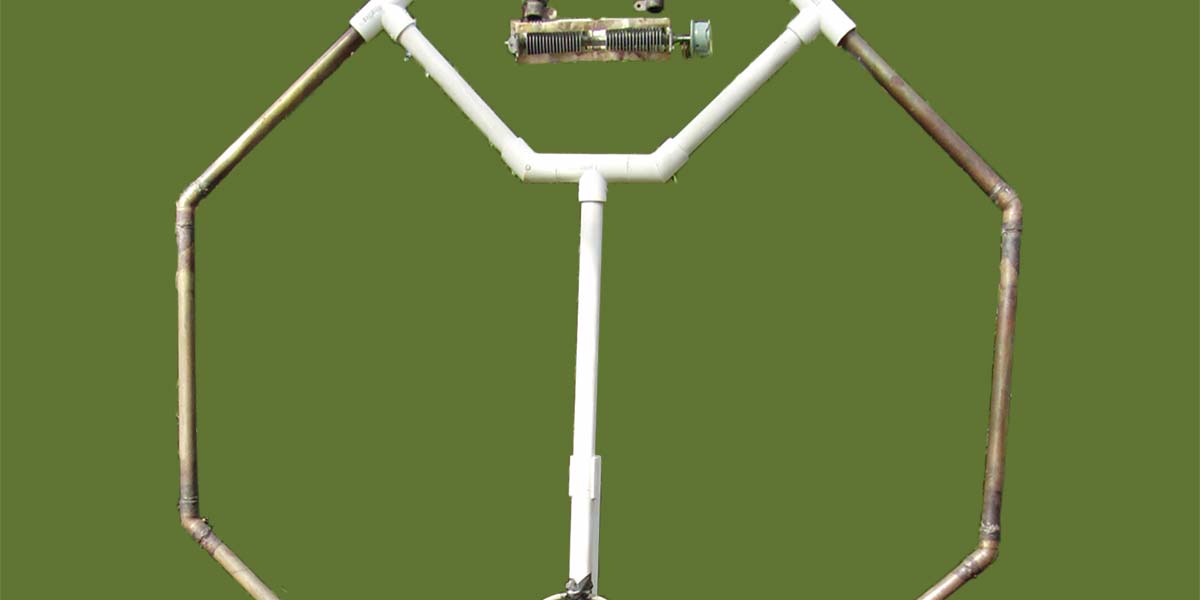
Antenna, tripod without 40M fixed capacitor.
My loop design presented here eliminates the use of vacuum variable capacitors because of the size, weight, and expense. Manual tuning is more practical for portable operation. For me, that meant it would be no more than 10 feet in circumference to fit in my car’s trunk, but with 40M-10M capability at 100 watts.
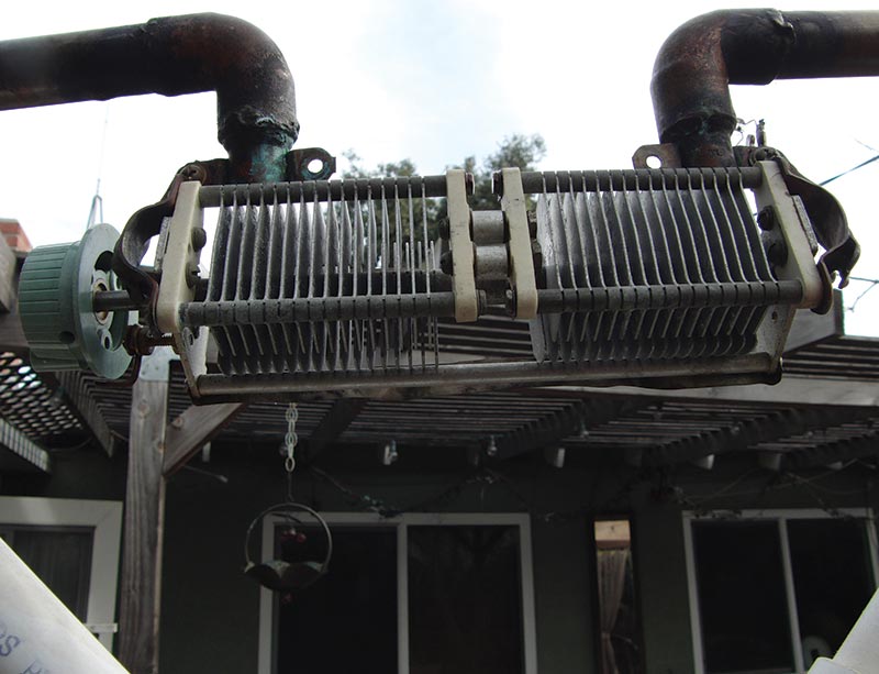
I had a Johnson dual 200 pF/2 KV in stock that would tune 30M-10M if you put both sections in series to get 100 pF/4 KV (use both ends and not the frame), thereby avoiding wiper contact resistance. A less expensive fixed vacuum capacitor can be added in parallel (in my case, 140 pF/5 KV) to the variable for 40M. Two low loss capacitors in parallel splits total current, which approaches 40A at 100W.
I cut a 10 foot section of type M 3/4 inch copper pipe into eight equal pieces (.875 OD) with the last piece split and shortened by the capacitor mount. Thicker pipe adds weight, but no noticeably better performance. Eight 45 degree elbows join the sections.
I used 15% silver brazing rods available on eBay for about $20 which is also 80% copper. Lead or tin are not good choices for conductivity. I used Silvaloy 15 but other brands are similar. Six or seven rods 20 inches in length were used.
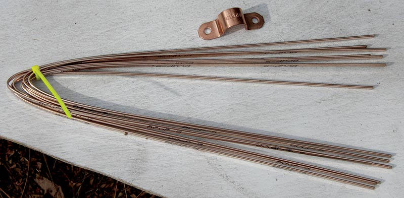
15% silver brazing rods and clamps for capacitors.
The joints need to be clean and bright; brazing them with a MAPP gas cylinder on a propane torch to get the extra heat works great. Fortunately, the learning curve is fast and no flux is needed.
I brazed them in the garage with the aid of a vice, although a warm day with no wind outside might be better. Using one inch copper tubing might be an option for some, but bending is likely difficult for the less experienced.
The DC resistance of the loop measured about 1.4 milliohms. A good small transmitting loop calculator is at www.66pacific.com. Their calculator for 40M said I needed about 10-12 pF more. That might have been due to stray capacitance in the construction, which turned out to be good since I was able to tune down to 6.8 MHz with no problems.
The fixed vacuum capacitor was only necessary on 40M, which was an initial concern. The final design tuned from 6.8–28.7 MHz, although the upper end could easily be extended by bending or removing a variable capacitor plate. Modified copper pipe U hold-downs are strong and were used to mount the capacitors.
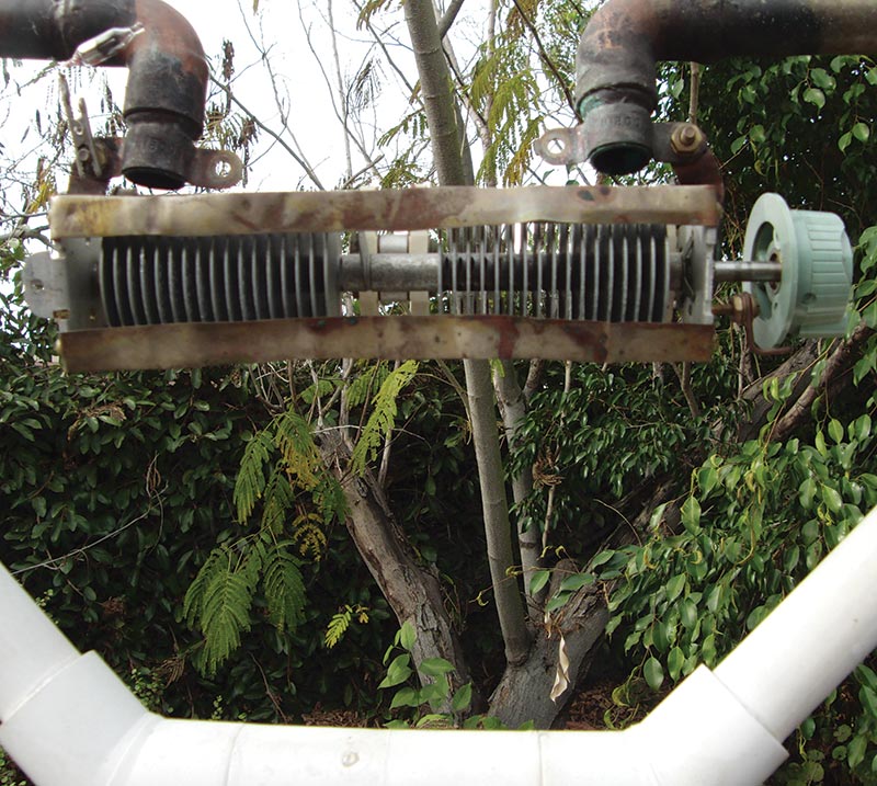
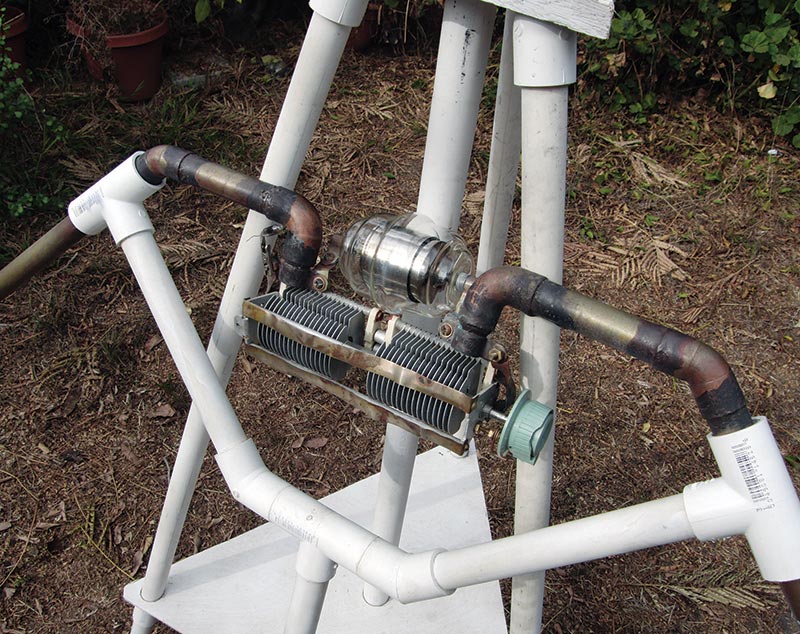
Tuning capacitor; copper straps across aluminum section for lower resistance.
Homebrew high voltage capacitor ideas are in the ARRL Antenna Book and on the Internet; just remember for 100W about 4KV is needed. During initial testing at 100W, the variable capacitor arced until I discovered a small leaf had fallen on it.
A popular way to match the antenna is with a small 1/5 diameter loop (eight inches of RG8X in this case). One end of the coax is soldered to the center and shell of the SO239 connector in the usual manner, but the other end has the braid not connected with the center coax wire soldered to the outside shell making a DC short. Some say this method is better because it provides an improved electrostatic shield and better pattern.
The feed loop can be put on the top or bottom. Mounting at the top makes the loop less top-heavy. However, RF is then coupled to the coax line hanging down and needs to be choked off by toroids or some other method.
No RF on the feedline was verified by moving my hands up and down the coax line close to the connector with no changes in SWR, which should result in better nulls. With the capacitor up higher, there is also less chance of detuning because of surrounding objects.
I got most of the parts from Home Depot, including the copper pipe U hold-downs which were hammered and used to attach the capacitors. Nuts were brazed on to the top section, so a brass screw could attach the fixed capacitor for 40M. A switch would be far too lossy.
The three 22 1/2 degree 3/4 inch PVC elbows used in the tripod are from Pvcpipesupplies.com for just a few dollars.
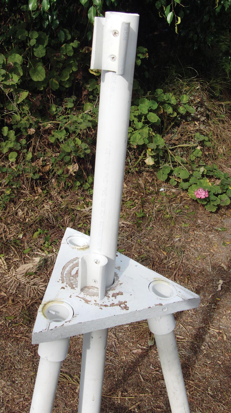
Top mount detail.
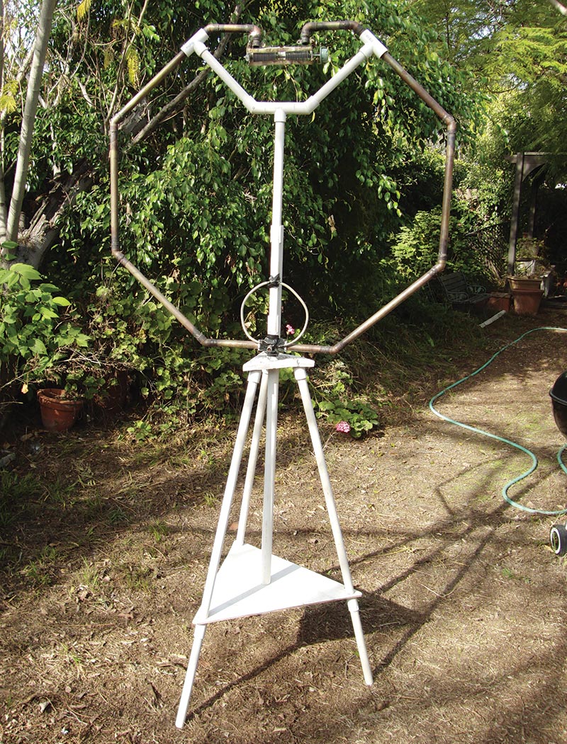
Using PVC for a frame is better because the less metal in the RF field, the better. Since the first H frame mount tried was too unstable, I tried the tripod mount with much better results, with easy assembly and disassembly.
The tripod needed 22 1/2 degree elbows because commonly-available 45 degree versions made the legs spread out too fast. The bottom portion of the tripod has a stop below the shelf which stabilizes it and allows weights on the bottom during windy conditions.
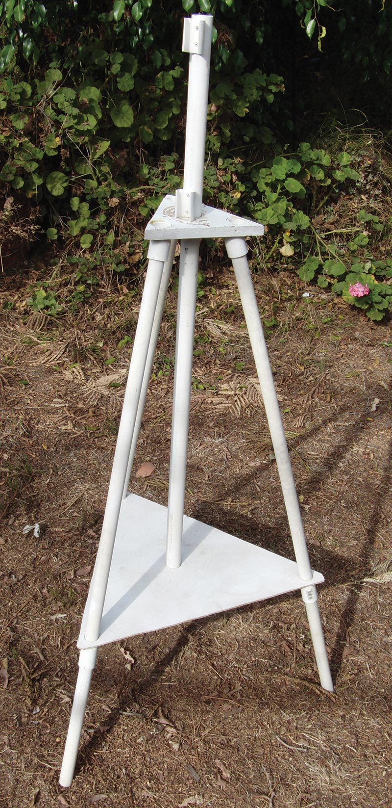
Tripod overview.
I used a 22-5/8 inch on a side 1/2 inch plywood for the bottom shelf but would use 5/16 next time. The top triangle was 8-5/8 inches on a side and was 3/4 inch thick pine (hardwood next time). All PVC pieces are 3/4 inch except the four foot/one inch mast which makes the tuning capacitor just reachable. The total diagonal length above the bottom shelf is 30-5/8 inches including the coupler, whereas the section below is 13 inches.
Tuning capacitor; holes for 40M fixed capacitor shown.
Painting the whole frame to reduce sun damage is desirable. The two PVC pieces attached to the mast are cut with an opening of .89 inches. This allows strong snap attachment but easy disassembly. The Y mount PVC Ts must be attached to the loop before brazing, using a wet rag to keep it cool. Next time, three or four inches lower would make it slightly less top heavy farther from the high voltage area, possibly extending the 10M upper frequency limit.
The SWR at resonance is 1.3 or less except for 10M where it is 1.6. The loss matching this low SWR with a tuner would likely be more than extra loss caused by the SWR. Peaking on receive noise is easy since it’s so sharp you might simplify operations by doing only that.
The 2:1 SWR bandwidth is:
40M 13 kHz
30M 35 kHz
20M 48 kHz
15M 80 kHz
10M 83 kHz (Likely more bandwidth,
but SWR starts at 1.6.)
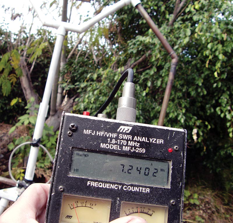
SWR on 40M.
At a Quartzfest demonstration last year, the loop was compared to a commercial loop of the same size but using aluminum tubing. Their 2:1 SWR bandwidth on 40M was 27 kHz vs. 13 kHz, but their extra loss could be heard by some comparing on the air signals. For about two hours a couple of months ago on 40M, this resulted in about 20 heard contacts from Alaska to New England with 200 mW — which is a testament to both WSPR and this antenna.
Tuning capacitor with 40M fixed capacitor attached.
RF exposure safety is a concern for small loop antennas. Using a low power SWR analyzer or peaking receiver noise is a safe alternative to low power SWR tuning. Kai Siwiak KE4PT mentioned in QST Technical Correspondence in May 2017 in part:
“Additionally, for a one meter diameter loop operating at a continuous 10W, including ground reflection, compliance distances are nearly constant over the 40-10 meter bands at less than 1.5 meters (4.9 feet) for the aware user, and 2.1 meters (6.9 feet) for the general public.”
Others have suggested even more distance (Notes 1, 2, 3, and 4) certainly with 100W.
Have fun and be safe! NV
Notes
K. Siwiak KE4PT, “RF Exposure Compliance Distances for Transmitting Loops, and Transmitting Loop Current” QST Technical Correspondence May 2017 pp 64-65.
K. Siwiak KE4PT, “Near Fields of an Electrically Small Loop Can Affect Direction Finding” QST July 2015 pp 63-64.
Jim Lux W6RMK in an extensive technical analysis letter to Steve Ford on Nov 29, 2006 about RF compliance with loop antennas
Table 17 in FCC OET65B; transition.fcc.gov/Bureaus/Engineering_Technology/Documents/bulletins/oet65/oet65b.pdf.